Page 1103 of 2189
Steering Gearbox
)
Removal
NOTE: Using solvent and a brush, wash any oil and dirt
off the valve body unit its lines. and the end if the gear-
box. Blow dry with comPressed air.
1. Drain the power steering fluid as described on page
2. Raise the front of vehicle, and support it on safety
stands in the proper locations (see section 11.
3, Remove the front wheels.
4. Remove the driver's airbag assembly, and steering
wheel (see page 17-35)
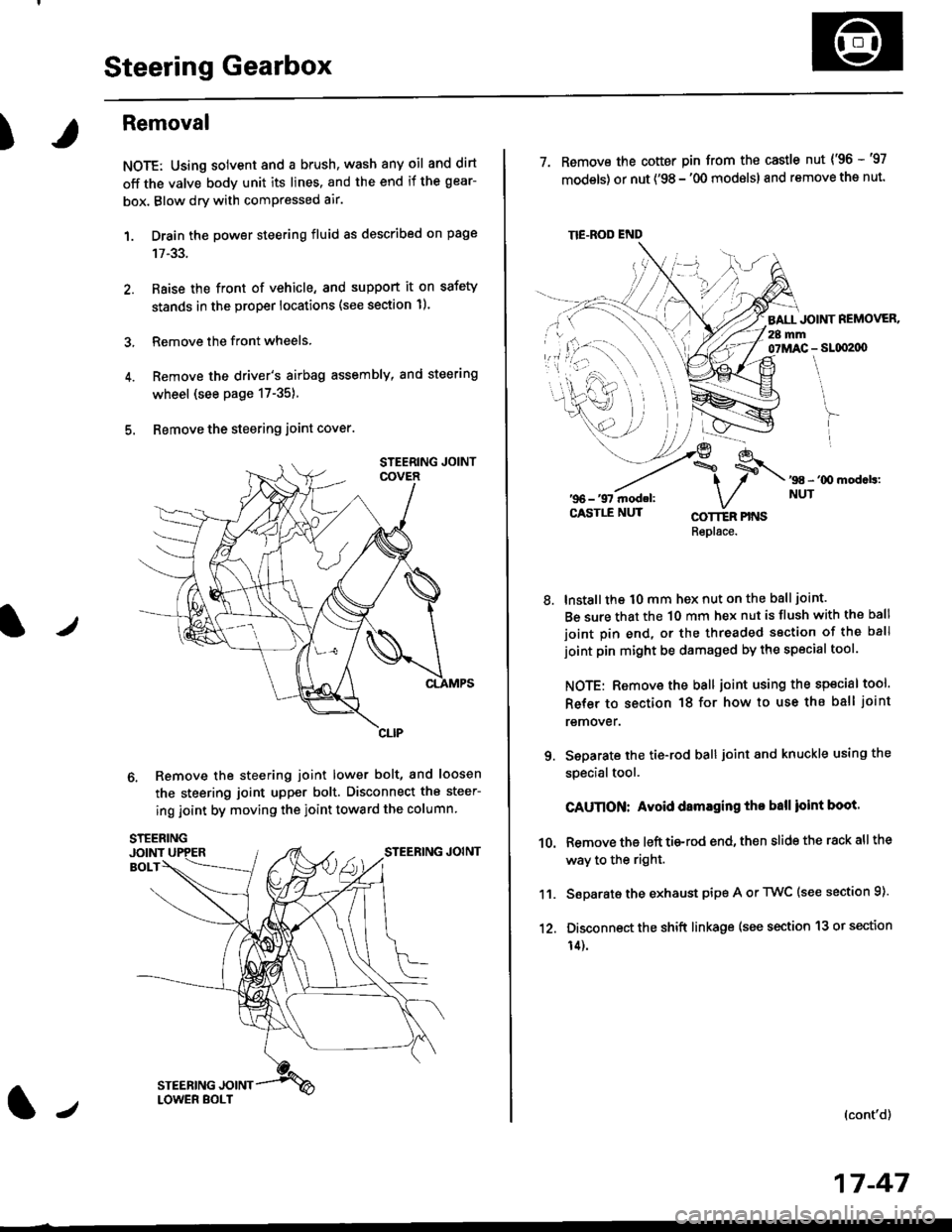
5. Bemove the steering joint cover.
6. Remove the steering joint lower bolt, and loosen
the steering joint upper bolt. Disconnect the steer-
ing joint by moving the ioint toward the column
tJ
17-47
TIE.ROD END
7. Remove the cotter pin from the castle nut {'96 -'97
models) or nut ('98 - '00 modslsl and remove the nut.
BALL JOINT REMOVER.28 mm07MAC - SLqI2|X)
'98 - '00 mod.b:NUT
8.
COTTER PINSRepl6ce.
lnstall the t0 mm hex nut on the ball joint.
Be sure that the 10 mm hex nut is flush with the ball
joint pin end, or the threaded section of the ball
joint pin might be damaged by the special tool.
NOTE: Remove the ball joint using the special tool.
Refer to section 18 for how to use ths ball joint
remover.
Seoarate the tie-rod ball joint and knuckle using the
specialtool.
CAUnON: Avoid damaging tho ball ioint boot.
Remove the left tie-rod end, then slide the rack all the
way to the right.
Separate the exhaust pipe A or TWC (see section 9).
Disconnect the shift linkage (see section 13 or section
14).
(cont'd)
9.
10.
11.
12.
Page 1105 of 2189
)
Disassembly
t)
Steering Rack DisassemblY
NOTE:
r Before disassemble the gearbox, wash it off with sol
vent and a brush.
. Do not dip seals and O-rings in solvent.
1. Remove the steering gearbox (see page 17-47]..
2. Remove the tie-rod end and locknut.
3. Remove air tube and cliPs.
Remove the boot bands and tie-rod clips Pull the
boots away from the ends of the gearbox.
BOOT
(|-,TIE.ROD CLIP
Hold the steering rack with a wrench ('98 -'00 mod-
els: left end only), and unscrew the rack end with
another wrench.
CAUTION: Be caroful not to damage the rack 3ur-
faco whh the wrench.
NOTE: '96 -'97 models is shown.
STEERING RACK END
STEERING RACK
Loosen the locknut, then remove the rack guide
screw and O-ring ('96 -'97 models only)
Remove the spring and the rack guide from the gear
housing.
7.
{cont'd}
17 -49
LOCK WASHER
Page 1111 of 2189
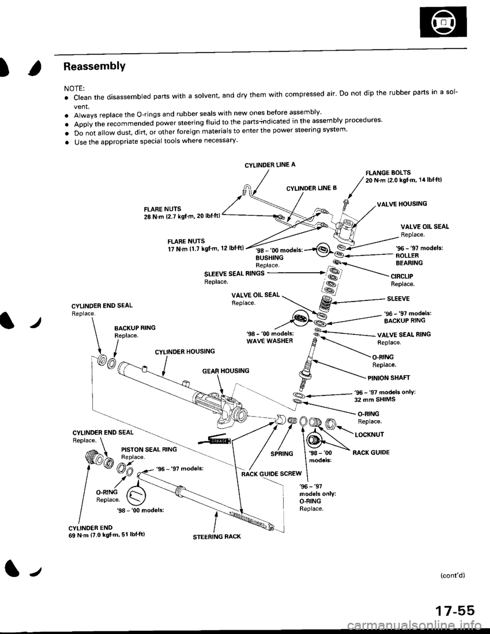
)Reassembly
NOTE:
. clean the disassembled parts wrth a solvent, and dry them with compressed air. Do not dip the rubber parts in a sol-
vent.
. Always replace the O-rings and rubber seals with new ones before assembly'
. Apply the recommended power steering fluid to the parts+ndicated in the assembly procedures'
o Do not a||ow dust, dirt, or other foreign materials to enter the power steering system.
a Use the appropriate special tools where necessary'
FLANGE BOLTS20 N.m (2.0 kgt'm, 14lbf ftl
CYLINDER LINE B
VALVE HOUSINGFLARE NUTS
28 N.m (2.7 ksf m,20 lbf ftl
VALVE OIL SEAL
Replace.
CYLINDER END SEAL
Replace.
f itllTllli".",'r'o,.n,ft
''*^'*-1$*€-/s6-,,mode,3:
EUSHINGReplace 'P'\-- BEARING
SLEEVE SEAL RINGS ..-------......�� SS
.----
",a"a,,
*---
--,
Replace. lss-, Replace.
Xll,Y5"l'.
"o. --r...- gY------..r.u,
,-f-..-S: _ ,96 _,9? models:
--€l€--------=- ircriip'ii.rt'-l./BACKUPReplace.
I,
wAvE wAsHER d
-.-.-r_ i"pru"".
CYLINDER HOUSING // -\-
, AJ - O.RING
/ ,S-'..- ReDtace.
_ j GEAR HouslNG l.g --'\-
\- t F
tonsrnrr
.,_- s
- 'oo ,,iod"t., -s-'--------- vALvE SEAL R'NG
S_.<---,tj- 97 models onlY:
CYLINDER END SEAL
)@OOD m n"prac".
/'\N,."._nrNG I '98 - 'oo - RACK GUIDE
models:
:scREw I
O.RINGReplace..98 - '00 models:
CYLINDER END69 N.m {?.0 kgt'm,51 lbl'ft)
(cont'd)
17-55
CYLINDER LINE A
tJ
Page 1120 of 2189
Steering Gearbox
Reassembly (cont'dl
64. Apply grease to the circumference of the rack endhousing.
RACK END GROOVE
=^.#-q!:s!!H
SILICONE GREASE
Apply a light coat of silicone grease to the bootgrooves on the rack ends.
lnstall the boots in the rack end with the tie-rodclips.
NOTE: Install the boots with the rack in the straightahead position (right and left tie-rods are equal inlength).
66.
RACK END
NOTE: Wipe the grease offthe thread section.
17-64
TIE.ROD CLIP
67. Adjust the air hose fitting position of the boots bvturning it as shown below.
LEFT BOOT(Viewed from theleft side)
RIGHT BOOT{Viewed from theright side)
AIR HOSE FITTING
Install new boot bands on the boot, and bend bothsets of locking tabs.
CAUTION: Stlke ths band locking tabs firmly.
Lightly tap on the doubled-over portions to reducetheir height.
Slide the rack right and left to be certain that theboots are not deformed or twisted.
Page 1121 of 2189
71.Connect the air tube between the right and left
boot.
lnstall the clips on the cylinder lines' then clamp the
air tube with the cliPs.
l./
CYLINDER LINE A
CLIP
l-,
lnstallation
CAUTION: Be carelul not to bend or damage the feed
line and cylinder lines when installing the gearbox'
1, Before installing the gearbox, slide the rack all the
way to right.
2. Install the mounting cushion on the steering gear-
DOX.
Install the pinion shaft grommet, then insert the pin-
ion shaft up through the bulkhead.
NOTE: Align the notch in the pinion shaft grommet
with the tab on the valve housing.
Install the mounting bracket over the mounttng
cushion, then installtwo gearbox mounting bolts'
MOUNTING BRACKET
cusHroN
39 N.m(4.0 kgj m, 29 lbtftlNOTE: Install the bracket
with the arrow Pornllngtoward the front.(cont'd)
17-65
Page 1122 of 2189
Steering Gearbox
Installation (cont'dl
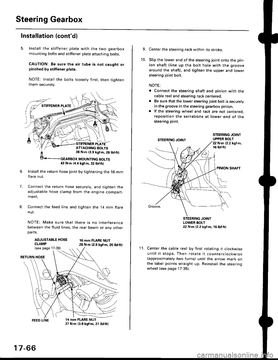
5. Install the stiffener plate with the two gearbox
mounting bolts and stiffener plate aftaching bolts.
CAUTION: Be sure the air tube is not caught orpinched by stiffener plate,
NOTE: Install the bolts loosely first, then tighten
them securely.
7.
8.
6.Install the return hose joint by tightening the l6 mm
flare nut.
Connect the relurn hose securely, and tighten the
adjustable hose clamp from the engine compart-ment.
Connect the feed line and tighten the 14 mm flare
nut.
NOTE: Make sure that there is no interference
between the fluid lines, the rear beam or any otherparts.
ADJUSTABLE HOSECLAMP(see page 17-39)
16 mm FLARE NUT28 N.m {2.9 ksl.m. 20 lbf.ft)
RETURN
1a mm FLARE NUT37 N.m (3.8 kg{.m, 27 lbt.ftl
ATTACHING AOLTS38 N.m 13.9 kgf.m, 28 lbf.ftl
MOUNTING BOLTS(} N.m (4.a kgt m, 32 lbf.ftl
17-66
9.Center the steering rack within its stroke.
Slip the lower end of the steering joint onto the pin-
ion shaft (line up the bolt hole with the groove
around the shaft), and tighten the upper and lower
steering joint bolt.
NOTE:
. Connect the steering shaft and pinion with the
cable reel and steering rack centered.. Be sure that the lower steering joint bolt is securely
in the groove in the steering gearbox pinion.
. lf the steering wheel and rack are not centered,
reposition the serrations at lower end of the
steering joint.
10.
STEERING JOINTUPPER BOLT22 N.m (2.2 kgf.m,16 tbt.ftl
PINION SHAFT
Groove,
STEERING JOINTLOWER BOLT22 N.m (2.2 kgt.m, 16lbtttl
11.Center the cable reel by first rotating it clockwise
until it stops. Then rotate it counterclockwise(approximately two turns) until the arrow mark onthe label points straight up. Reinstall the steeringwheel (see page 17 35).
Page 1123 of 2189
)
1?
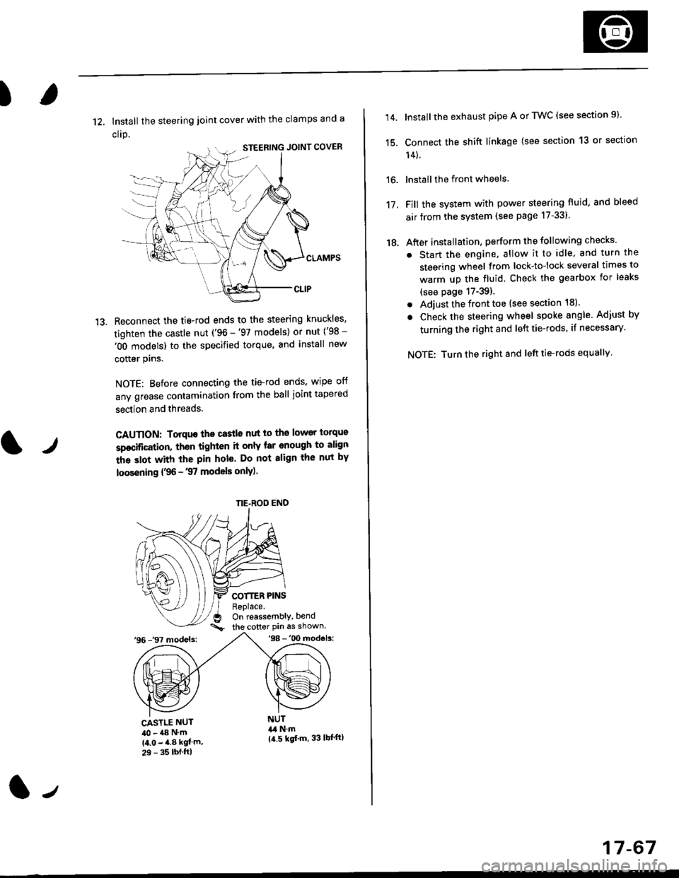
12, Install the steering joint cover with the clamps and a
clrp.
Reconnect the tie-rod ends to the steering knuckles,
tighten the castle nut ('96 -'97 models) or nut ('98 -
'OO models) to the specified torque, and install new
cotter plns.
NOTE: Before connecting the tie-rod ends, wipe off
any grease contamination from the ball joint tapered
section and threads.
CAUTION: Torquo the castle nut to the lower torque
sp€cification, then tighten it only tar enough to align
the slot with the pin hole. Do not align the nut by
loosening {,96 -'97 models only).
COTTER PINSReplace.On reassembly, bend
the cotter Pin 6s shown.'96 -'97 models:'98 -'00 mod€ls:
tr
CASTLE NUT40 - a8 N'm(4.0 - 4.8 kgf'm,29 - 35 lbf.ftl
NUT&l N.m{a.5 kgf'm, 33 lbl'ftl
NE-ROD END
(l-,
17-67
14.
15.
16.
17.
18.
Install the exhaust pipe A or TWC (see section 9).
Connect the shift linkage (see section 13 or section
14).
lnstall the front wheels
Fill the system with power steering fluid, and bleed
air from the system (see page 17-331
After installation, perform the following checks
. Start the engine, allow it to idle, and turn the
steering wheel from lock-tolock several times to
warm up the fluid. Check the gearbox for leaks
(see page 17-39).
. Adjust the front toe (see section 18).
. Check the steering wheel spoke angle. Adjust by
turning the right and left tie-rods, if necessary.
NOTE: Turn the right and left tie-rods equallv
Page 1124 of 2189
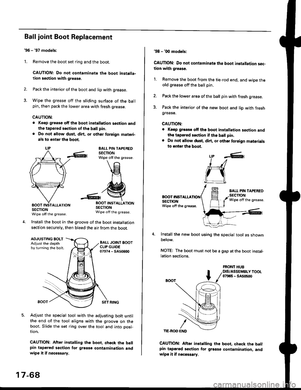
Ball joint Boot Replacement
'96 - '97 models:
1. Remove the boot set ring and the boot.
CAUTION: Do not contaminate the boot installa.tion section with grsase.
2. Pack the interior of the boot and lip with grease.
3. Wipe the grease off the sliding surface of the ballpin, then pack the lower area with fresh grease.
CAUTION:
. Keep grease off the boot installation seciion andthe tapered s€ction ot the ball pin.
. Do not allow dust, dirt, or oth6r foreign materi-
als to 6nt8r the boot.
LIPEALL PIN TAPEREDSECTIONWipe off the grease.
INSTALLATION
SECTIONWipe off the grease.
Install the boot in the groove of the boot installation
section securely, then bleed the air from the boot.
-6lrBOOTSECTIONWipe off the grease
4.
ADJUSTING BOLTAdjust the depthby turning the bolt.
SET RING
Adjust the special tool with the adjusting bolt untilthe end of the tool aligns with the groove on theboot. Slide the set ring over the tool and into posi-
UOn.
CAUTION: After installing the boot, qhsck the ballpin tapered section for grease contamination andwipe it it necGsary.
17-68
'98 - '00 models:
CAUTION: Do not contaminato the boot installation sec-tion with grease.
1. Remove the boot from the tie-rod end, and wiDe theold grease off the ball pin.
2. Pack the lower area ofthe ball pin with fresh grease.
3. Pack the interior of the new boot and liD with freshgrease.
CAUTION:
. Keop groasc ott tho boot installalion sestion andth. iapored s.ction if th€ ball pin.
. Do not allow dust. dirt, or other foreign materials
to entor tho boot.
BOOT INSTALLASECTIONWipe off the gr€ase,
Install the new boot using the special tool as shownbelow.
NOTE: The boot must not be a gap atthe boot installation sections.
LtP .6r
J_/
ru
CAUTION: Aftor installing the boot, chock the batlpin tapgred section tor grgase cortamination. andwipe it it n€ces3ary.
FRONT HUBDIS/ASSEMBLY TOOL07965 - SA5o500