2000 HONDA CIVIC Body
[x] Cancel search: BodyPage 1274 of 2189
Ouarter Glass
Installation (cont'd)
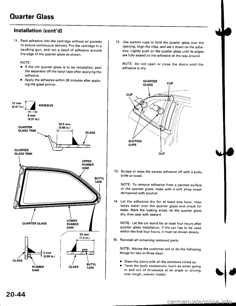
11. Pack adhesive into the cartridge without air pockets
to ensure continuous delivery. put the canridge in acaulking gun, and run a bead of adhesive aroundthe edge of the quarter glass as shown.
NOTE:
. lf the old quarter glass is to be reinstalled, peelthe separator off the butyl tape after applying theadhesive.
. Apply the adhesive within 30 minutes after apply_ing the glass primer.
i:.8i".,1/:ADHES,'E
8 rnm(0.31 in.l
OUARIERGLASS TRIM
OUARTERGLASS TFIM
BUTYI.TAPE
OUARTER GLASS
[-4m,^,GLASS \
32 mm{1.3 in.)
''='I
'"r"\
/ drt".GLASS TAPE
20-44
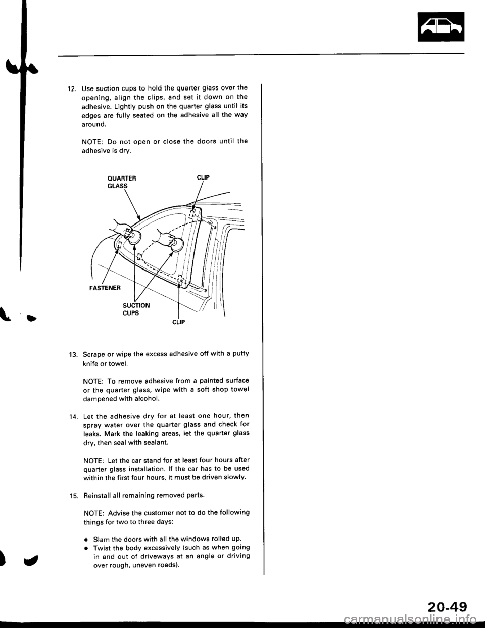
12. Use suction cups to hold the quarter glass over theopening, align the clips, and set it down on the adhe-sive. Lightly push on the quaner glass until its edgesare fully seated on the adhesive all the way around.
NOTE: Do not open or close the doors until theadhesive is drv.
Scrape or wipe the excess adhesive off with a puttyknife or towel.
NOTE: To remove adhesive from a painted surfaceor the quarter glass, wipe with a soft shop toweldampened with alcohol.
Let the adhesive dry for at least one hour, thenspray water over the quarter glass and check forleaks. Mark the leaking areas, let the quarter glass
dry, then seal with sealant.
NOTE: Let the car stand for at least four hours afterquarter glass installation. lf the car has to be usedwithin the first four hours, it must be driven slowly.
Reinstall all remaining removed parts.
NOTE: Advise the customer not to do the followingthings for two to three days:
. Slam the doors with all the windows rolled up.. Twist the body excessively (such as when goingan and out of driveways at an angle or drivingover rough, uneven roads).
15.
14.
CLIP
Page 1276 of 2189
Ouarter Glass
1.
Installation
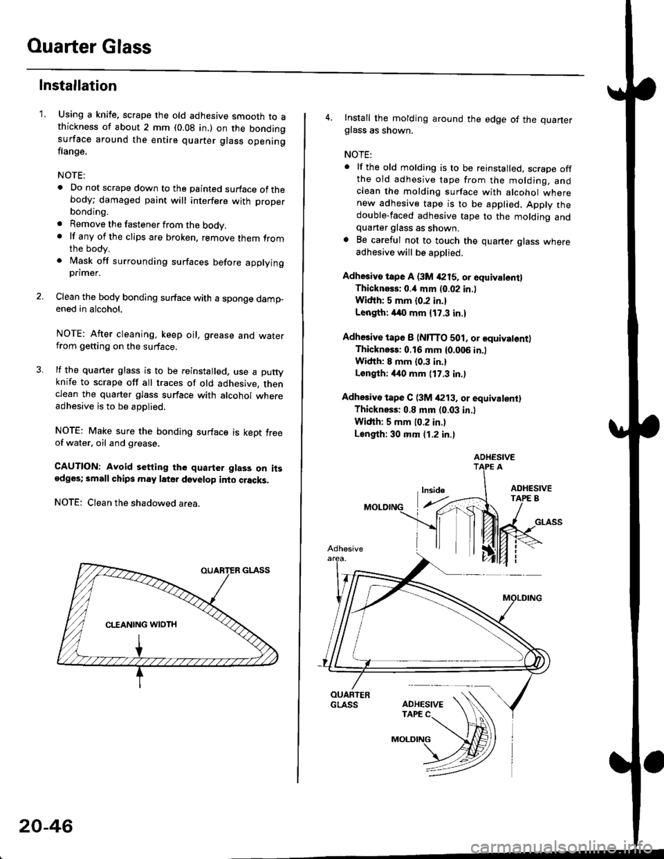
Using a knife, scrape the old adhesive smooth to athickness of about 2 mm (0.08 in.) on the bondingsurface around the entire quarter glass openingflange.
NOTE:
. Do not scrape down to the painted surface of thebody; damaged paint will interfere with proper
a
a
bonding.
Remove the fastener from the body.lf any of the clips are broken, remove lhem fromthe body.
Mask off surrounding surfaces before applyingpnmer.
Clean the body bonding surface with a sponge dampened in alcohol.
NOTE: After cleaning, keep oil, grease and waterfrom getting on the surface.
lf the quarter glass is to be reinstalled, use a puttyknife to scrape off all traces of old adhesive. thenclean the quarter glass surface with alcohol whereadhesive is to be applied.
NOTE: Make sure the bonding surface is kept freeof water. oil and grease.
CAUTION: Avoid setting the quarter glass on itsodges; small chips may later develop into cracks,
NOTE: Clean the shadowed area.
20-46
4. Install the molding around the edge of the quarterglass as shown.
NOTE:
. lf the old molding is to be reinstalled, scrape offthe old adhesive tape from the molding, andclean the molding surface with alcohol wherenew adhesive tape is to be applied. Apply thedouble-faced adhesive tape to the molding andquarter glass as shown.. Be careful not to touch the quarter glass whereadhesive will be aoDlied.
Adhesiv€ tspe A (3M 4215, or equivalent)Thicknsss: o.il mm (0.02 in.l
Widih: 5 mm {0.2 in.}
Length: /140 mm {17.3 in.)
Adhesive tap6 I (NITTO 501, or equivatontlThickness: 0.16 mm {0.006 in.)
Width: I mm {0.3 in.}
Longlh: 4it0 mm (17.3 in.)
Adhosiv€ tape C (3M /P13. or equivalentl
Thickness: 0.8 mm (0.03 in.l
Width: 5 mm (0.2 in.)
Length: 30 mm (1.2 in.)
ADHESIVE
Page 1277 of 2189
t
\b
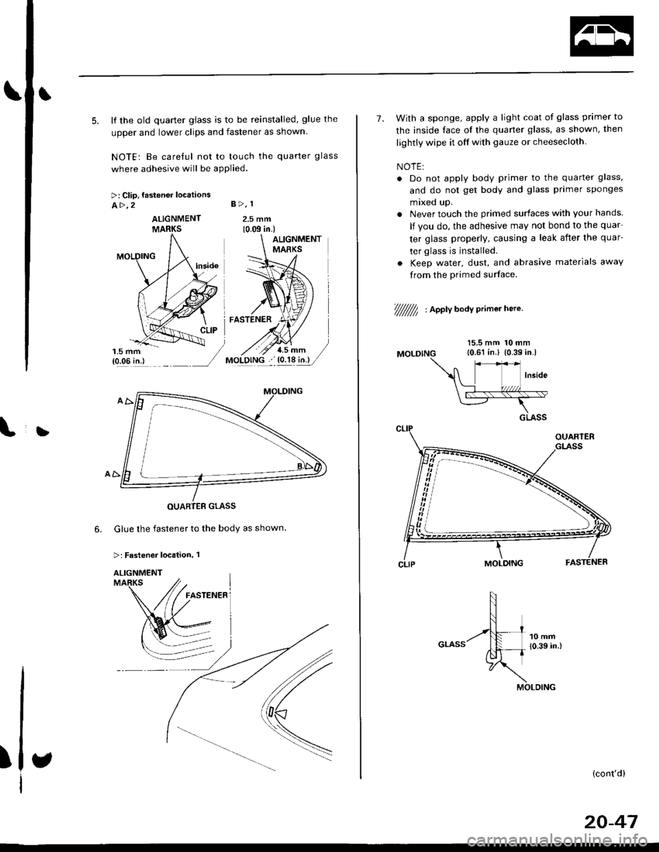
5. lf the old quarter glass is to be reinstalled, glue the
upper and lower clips and fastener as shown
NOTE: Be careful not to touch the quarter glass
where adhesive will be applied.
>: Clip, fastener locations
A>,2 B>, 1
2.5 mm(0.m in.)
Glue the fastener to the body as shown.
>: Fastener location, 1
6.
)
ALIGNMENT
7. With a sponge, apply a light coat of glass primer to
the inside face of the quaner glass, as shown, then
lightly wipe it off with gauze or cheesecloth
NOTE:
. Do not apply body primer to the quarter glass,
and do not get body and glass primer sponges
mixed up.
. Never touch the primed surfaces with your hands.
lf you do, the adhesive may not bond to the quar
ter glass properly, causing a leak after the quar-
ter glass is installed.
. Keep water, dust, and abrasive materials away
from the Primed surface
t///////7, , aootv a"av crimer here'
MOLDING
15.5 mm 10 mm10.61 in.l {0.39 in.l
(cont'dl
20-47
Page 1278 of 2189
Ouarter Glass
Installation (cont'dl
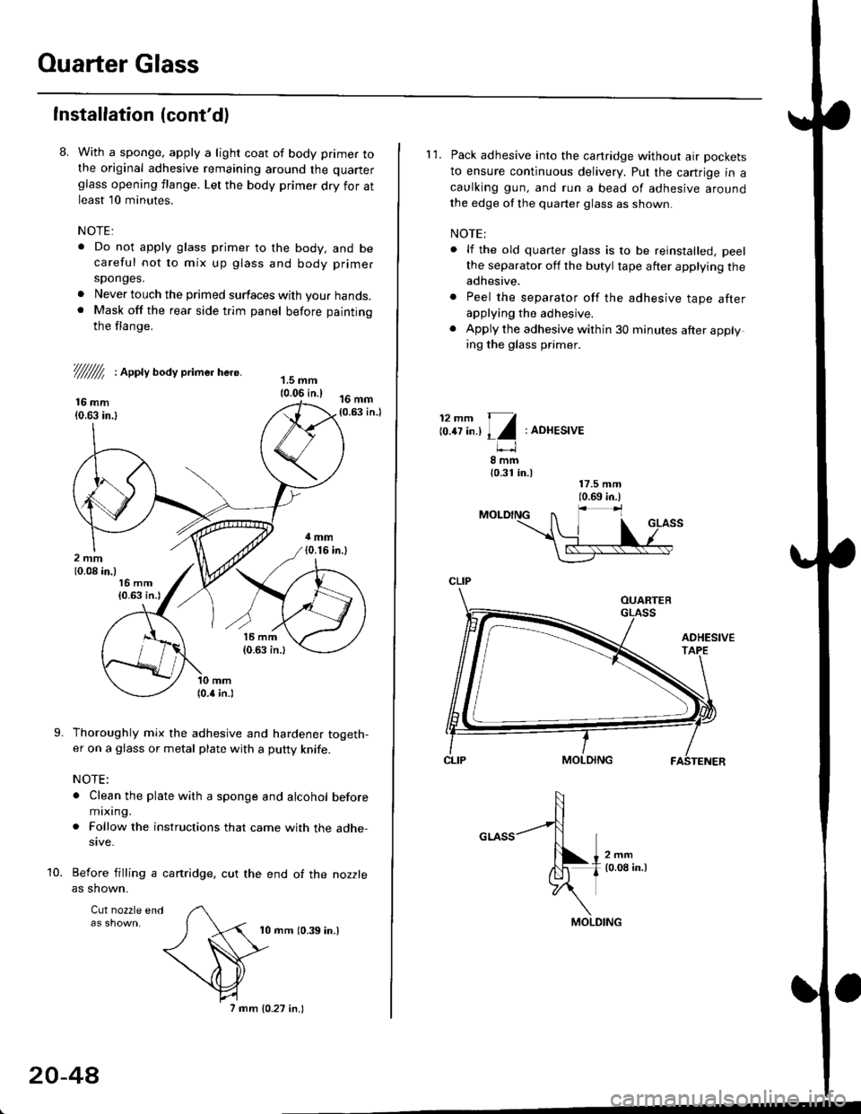
8. With a sponge, apply a light coat of body primer tothe original adhesive remaining around the quarter
glass opening flange. Let the body primer dry for atleast l0 minutes.
NOTE:
. Do not apply glass primer to the body, and becareful not to mix up glass and body primer
sponges.
. Never louch the primed surfaces with your hands.. Mask off the rear side trim panel before painting
the flange.
///ffi : Appty aoay primer here.
16 mm10.63 in.l
Thoroughly mix the adhesive and hardener togeth-er on a glass or metal plate with a putty knife.
NOTE:
. Clean the plate with a sponge and alcohol beforemixing.
. Follow the instructions that came with the adhe-sive.
Before filling a cartridge, cut the end of the nozzle
as shown.
Cul nozzle end
10 mrn (0.39 in.)
9.
10.
20-4A
7 mm 10.27 in.)
l'1. Pack adhesive into the canridge without air pockets
to ensure continuous delivery. Put the cartrige in a
caulking gun, and run a bead of adhesive around
the edge of the quarter glass as shown.
NOTE:
. lf the old quarter glass is to be reinstalled, peel
the separator off the butyl tape after applying theadhesive.
. Peel the separator off the adhesive tape afterapplying the adhesive.
. Apply the adhesive within 30 minutes after applying the glass primer.
12mm 11
lo.tt tn.l I l:ADHESIVE
8mm{0.31 in.)
CLIP
MOLDING
Page 1279 of 2189
}
12. Use suction cups to hold the quarter glass over the
opening, align the clips, and set it down on the
adhesive. Lightly push on the quarter glass until its
edges are fully seated on the adhesive all the way
around.
NOTE: Do not open or close the doo.s until the
adhesive is dry.
Scrape or wipe the excess adhesive off with a putty
knife or towel,
NOTE: To remove adhesive from a painted surface
or the quaner glass, wipe with a soft shop towel
dampened with alcohol.
Let the adhesive dry for at least one hour, then
spray water over the quarter glass and check for
leaks. Mark the leaking areas, let the quarter glass
dry, then seal with sealant.
NOTE: Let the car stand for at least four hours after
quarter glass installation. lf the car has to be used
within the first four hours, it must be driven slowly
Reinstall all remaining removed parts-
NOTE: Advise the customer not to do the following
things for two to three days:
. Slam the doors with all the windows rolled up.
. Twist the body excessively (such as when going
in and out of driveways at an angle or driving
over rough, uneven roadsl.
13.
14.
)
CLIP
a
20-49
Page 1285 of 2189
L
L
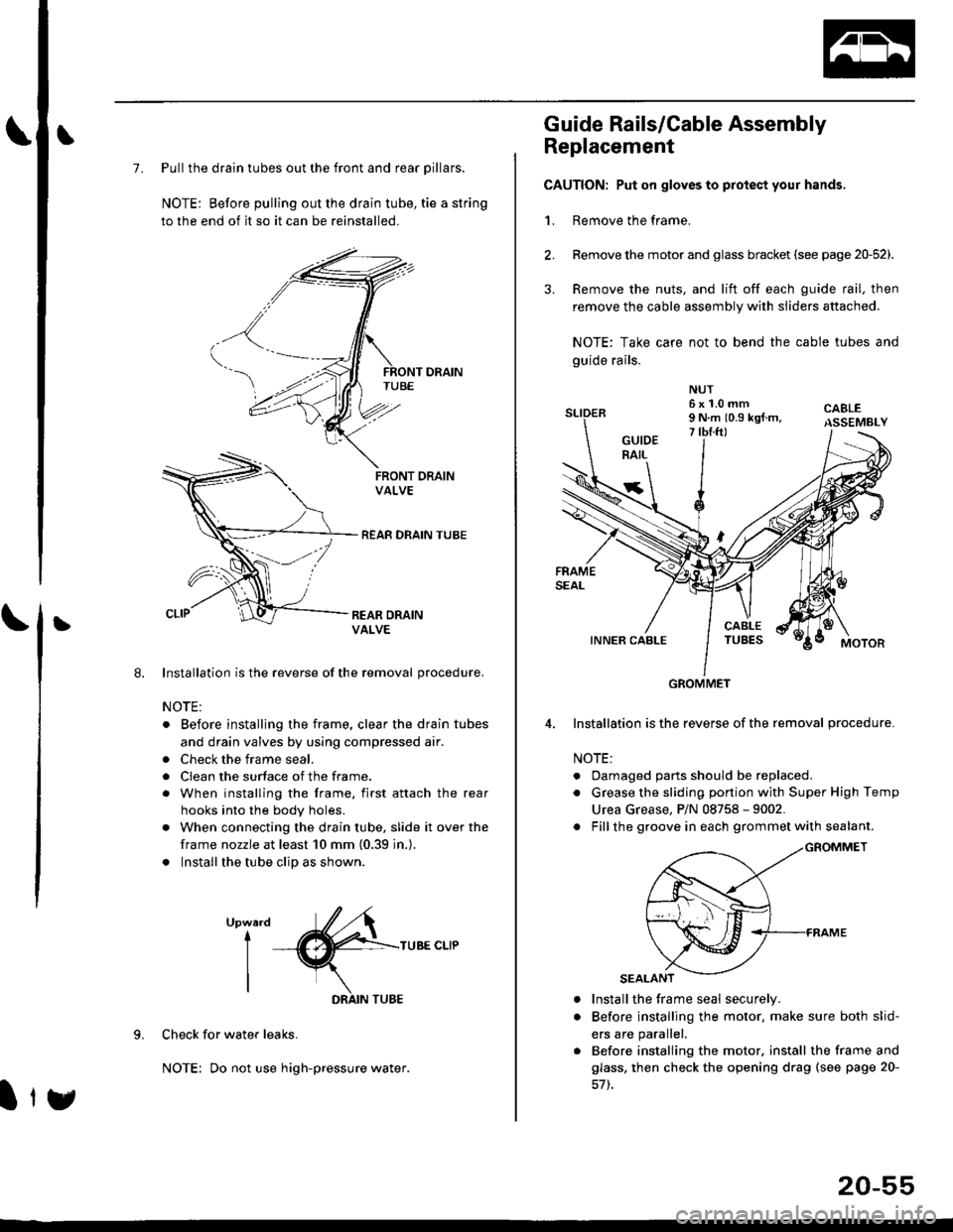
7. Pull the drain tubes out the front and rear pillars.
NOTE: Before pulling out the drain tube, tie a string
to the end of it so it can be reinstalled.
Installation is the reverse of the removal procedure.
NOTE:
. Before installjng the frame, clear the drain tubes
and drain valves by using compressed air.
. Check the frame seal.
. Clean the surface of the frame.
. When installing the frame, first attach the rear
hooks into the body holes.
. When connecting the drain tube, slide it over the
frame nozzle at least 10 mm (0.39 in.).
. Install the tube clip as shown.
UpwardI
I
I
TUBE CLIP
Check for water leaks.
NOTE: Do not use high-pressure water.
DRAIN TUBE
Ity
20-55
Guide Rails/Cable Assembly
Replacement
CAUTION: Put on gloves to protect your hands,
1. Remove the frame.
Remove the motor and glass bracket (see page 20-52).
Remove the nuts, and lift off each guide rail, then
remove the cable assembly with sliders attached.
NOTE: Take care not to bend the cable tubes and
guide rails.
Installation is the reverse of the removal procedure.
NOTE:
. Oamaged parts should be replaced.
. Grease the sliding portion with Super High Temp
Urea Grease, P/N 08758 - 9002.
. Fillthe groove in each grommet with sealant.
a
a
Install the frame seal securely.
Before installing the motor. make sure both slid-
ers are parallel.
Before installing the motor. install the frame and
glass, then check the opening drag (see page 20-
GROMMET
Page 1295 of 2189
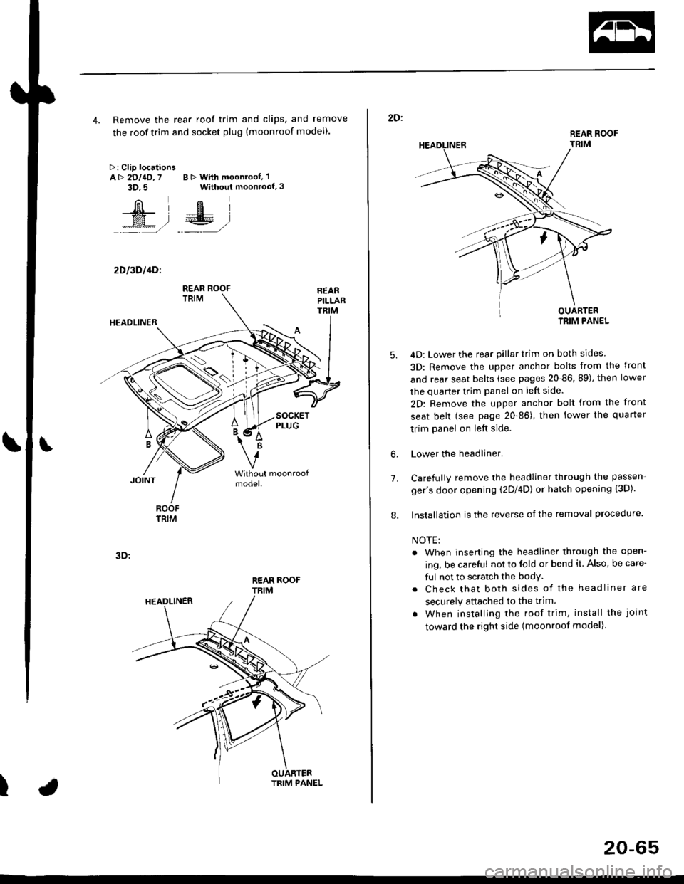
4. Remove the rear roof trim and clips, and remove
the roof trim and socket plug (moonroof model).
>: Clip locationsA> 2DllD,7 B > With moonroof, 'l
3D.5 Without moonroof,3
[il',fEl
t% .l €E .l':: =,/ _._- ,/
2D l3D l4Dl
REAR ROOFTRIM
3D:
t
REAR ROOF
TRIM
2D:
5.
7.
OUARTERIRIM PANEL
4D: Lower the rear pillar trim on both sides
3D: Remove the upper anchor bolts from the front
and rear seat belts (see pages 20-86, 89), then lower
the quarter trim panel on left side.
2D: Remove the upper anchor bolt from the front
seat belt (see page 20-86), then lower the quaner
trim panel on left side.
Lower the headliner.
Carefully remove the headliner through the passen-
ger's door opening (2Dl4D) or hatch opening (3D).
Installation is the reverse of the removal procedure.
NOTE:
. When inserting the headliner through the open-
ing, be careful not to fold or bend it. Also, be care-
ful not to scratch the bodY.
. Check that both sides of the headliner are
securely attached to the trim.
. When installing the roof trim, install the joint
toward the right side (moonroot model)
6.
8.
20-65
Page 1300 of 2189
Dashboard
Gomponent Removal/lnstallation
(cont'd)
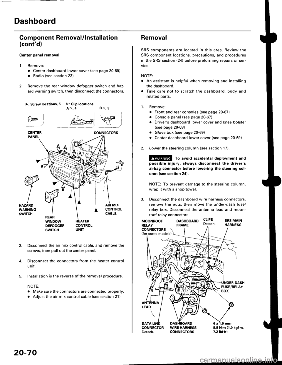
Center panel removal:
1. Remove:
. Center dashboard lower cover (see page 20-69)
. Radio {see section 23)
2. Remove the rear window defogger switch and haz-
ard warning switch, then disconnect the connectors.
>: Screw locations, 5 >: Clip locationsA>,4 B>,3
fii*-)
CENTERPANEI.
rt-xR.
W
IHAZARDWARNINGswlTcH
r44 "
F.IZvl
IIREARwtNoowOEFOGGERswtrcH
MtxCONTNOLCABLE
3. Disconnect the air mix control cable, and remove the
screws, then pull out the center panel.
4. Disconnect the connectors from the heater control
u nit.
5. Installation is the reverse of the removal procedure.
NOTE:
. Make sure the connectors are connected properly.
. Adjust the air mix control cable (see section 21).
20-70
Removal
SRS components are located in this area. Review the
SRS component locations, precautions, and procedures
in the SRS section (24) before preforming repairs or ser-
vice.
NOTE:
. An assistant is helpful when removing and installing
the dashboard.
. Take care not to scratch the dashboard, body and
related parts.
1. Remove:
o Front and rear consoles (see page 20-67)
. Console panel (see page 2O 67),
. Driver's dashboard lower cover and knee bolster(see page 20-68)
. Glove box (see page 20-69)
. Center dashboard lower cover (see page 20-69i
2. Lower the steering column (see section 17).
@ To avoid accidental deplovment and
possible injury, always disconnect the driver's
airbag connector belore lowering the steering col-
umn lsee section 241.
NOTE: To prevent damage to the steering column,
wrap it with a shop towel.
3. Disconnect the dashboard wire harness connectors,
remove the nuts, then move the under-dash fuse/
relay box. Disconnect the antenna lead and moon-
roof relay connectors.
DASHBOARD cltPs
CONNECTORS(for some models)
MOONROOFRELAY
ANTENNALEAO
FRAME
SRS MAINHARNESS
9.8 N.m (1.0 kgf m,7.2lbt.ltl
DATACONNECTOR WIRE HARNESSDetach. CONNECTORS