2000 HONDA CIVIC check engine
[x] Cancel search: check enginePage 1123 of 2189
)
1?
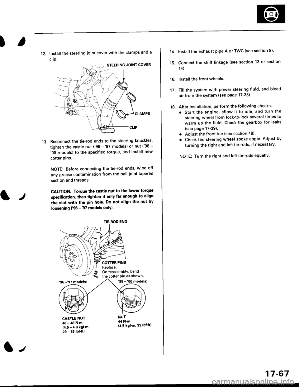
12, Install the steering joint cover with the clamps and a
clrp.
Reconnect the tie-rod ends to the steering knuckles,
tighten the castle nut ('96 -'97 models) or nut ('98 -
'OO models) to the specified torque, and install new
cotter plns.
NOTE: Before connecting the tie-rod ends, wipe off
any grease contamination from the ball joint tapered
section and threads.
CAUTION: Torquo the castle nut to the lower torque
sp€cification, then tighten it only tar enough to align
the slot with the pin hole. Do not align the nut by
loosening {,96 -'97 models only).
COTTER PINSReplace.On reassembly, bend
the cotter Pin 6s shown.'96 -'97 models:'98 -'00 mod€ls:
tr
CASTLE NUT40 - a8 N'm(4.0 - 4.8 kgf'm,29 - 35 lbf.ftl
NUT&l N.m{a.5 kgf'm, 33 lbl'ftl
NE-ROD END
(l-,
17-67
14.
15.
16.
17.
18.
Install the exhaust pipe A or TWC (see section 9).
Connect the shift linkage (see section 13 or section
14).
lnstall the front wheels
Fill the system with power steering fluid, and bleed
air from the system (see page 17-331
After installation, perform the following checks
. Start the engine, allow it to idle, and turn the
steering wheel from lock-tolock several times to
warm up the fluid. Check the gearbox for leaks
(see page 17-39).
. Adjust the front toe (see section 18).
. Check the steering wheel spoke angle. Adjust by
turning the right and left tie-rods, if necessary.
NOTE: Turn the right and left tie-rods equallv
Page 1135 of 2189
)
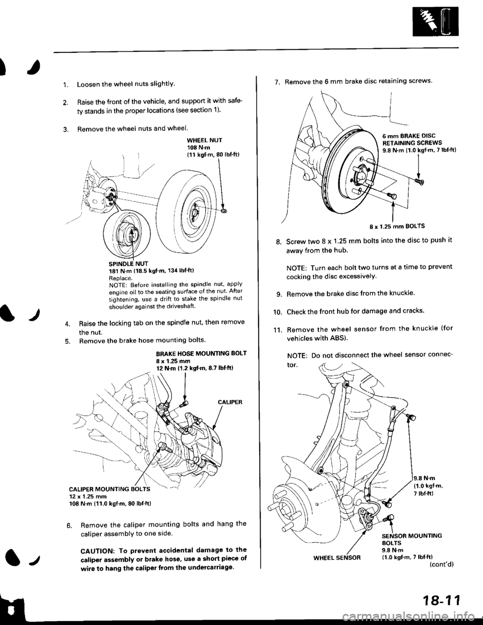
1.Loosen the wheel nuts slightlY.
Raise the front of the vehicle, and support it with safe-
ty stands in the proper locations (see section 1).
Remove the wheel nuts and wheel.3.
l)
WHEEL NUT'108 N.m
18'l N.m 118.5 kgf m, 134lblfti
Replace.NOTEI Before installing the spandle nut, apply
engine oil to the seating surface of the nut After
tightening, use a drift to stake the spindle nut
shoulder againsl the driveshaft
Raise the locking tab on the spindle nut, then remove
the nut.
Remove the brake hose mounting bolts.
BRAKE HOSE MOUNTING BOLT
I x 1.25 mm12 N.m (1,2 kgtm,8,7 lbf'ftl
6. Remove the caliper mounting bolts and hang the
caliper assembiy to one side
CAUTTON: To prevent accidental damage to the
caliper assembly or brake hoso' use a short piece of
wire to hang the caliPer tlom lhe undelcarriage.
{11 kgf m, 80 lbl.ft)
CALIPER MOUNTING BOLTS12 x 1.25 mm108 N.m {'11.0 kgtm, 80 lbt.ft)
7. Remove the 6 mm brake disc retaining screws.
8.
I x 1.25 mm BOLTS
Screw two 8 x 1.25 mm bolts into the disc to push it
away from the hub,
NOTE: Turn each bolt two turns at a tame to prevent
cocking the disc excessivelY.
Remove the brake disc from the knuckle.
Check the front hub for damage and cracks.
Remove the wheel sensor from the knuckle (for
vehicles with ABS).
NOTE: Do not disconnect the wheel sensor connec-
tor.
N.m
6 mm BRAKE OISCRETAINING SCREWS9.8 N.m t1.0 kgf.m, 7 lbf'ft)
{'1.0 kgf m,
7 tbf.ft)
10.
11.
MOUNTING
WHEEL
BOLTS9.8 N.m11.0 kgf,m, 7 lbf'ft)(cont'd)
Page 1147 of 2189
IHub Bearing Unit RePlacement
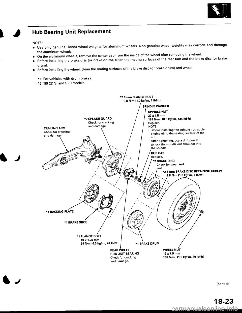
For vehicles with drum brakes.'99 2D Si and Si-B models
NOTE:
o Use only genuine Honda wheel weights for aluminum wheels Non-genuine wheel weights may corrode and damage
the aluminum wheels.
.onthea|uminumwhee|s,removethecentercapfromtheinsideoftheWhee|afterremovingthewhee|'
. Before insta||ing the brake disc (or brake drum), c|ean the mating surfaces of the rear hub and the brake disc (or brake
orum,.
. Before installing the wheel, clean the mating surfaces ofthe brake disc(or brake drum) andwheel'
*1:
*2'.
12 6 mm FLANGE BOLT
9.8 N.m {1.0 kgf m, 7 lbf'ft|
*2 SPLASH GUAROCheck for crackingand damage.
SPINDLE WASTIER
SPINDLE NUT
22 x 1.5 mm181 N,m (18.5 kgt'm. 134lbfft)
Replace.NOTE:' Before installing the spindle nut, apply
engine oil to the seating surface of the
nut,' After tightening, use a drift Punchto lock the spindle nut shoulder into
TRAILING ARMCheck for crackingand oamage,
lr
the spindle.
HUB CAPBeplace.12 BRAKE DISCCheck for wear and
rust,'2 6 mm BRAKE DISC RETAINING SCREW
9.8 N'm 11.0 kgt m, 7 lbf'ft|
)
*1 BACKING PLATE
/\*1 BRAKE SHOE
r1 FLANGE BOLT10 x 1.25 mm6,0 N.m (6.5 ksl.m,47 lbl'ftl
REAB
'1 BRAKE ORUM
HUB UNIT BEARING
Check for crackingand damage.
WHEEL NUT12 x 1.5 mm108 N.m {11.0 kgt'm.80lbt'ft)
(cont'd)
1A-23
l-t
Page 1148 of 2189
Rear Suspension
Hub Bearing Unit Replacement (cont'dl
NOTE: Disc type {'99 2D Si and Si-R modets)
1. Loosen the wheel nuts slightly.
2. Raise the rear of vehicle, and support it with safetystands in the proper locations {see section 1).
3. Remove the wheel nuts and rear wheel.
4. Pull the parking brake lever up.
5. Remove the hub cap.
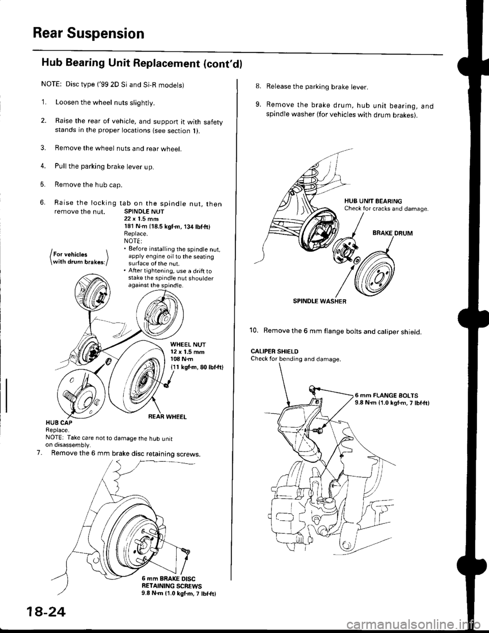
6. Raise the locking tab on the spindle nut, thenremove the nut. SPINDLE NUT22 x 1.5 mrn181 N.m (18.5 kgf'm, 134lbf.fi)Replace.NOT€:. Eefore installing the spindle nut,apply engine oil to the seatingsurface of the nut.. After tightening, use a drift tostake the spindle nut shoulderagainst the spindle.
lFor vehictes \\with drum brakes;/
WHEEL NUT12 x 1.5 mm108 N.m
I I 1 kgt m, 80 lbf.ftl
HUB CAPReplace-NOTE: Take care not to damage the hub untton disassembly.
Remove the 6 mm brake disc retaining screws.7.
6 mm BRAKE DISCRETAINING SCBEWS9.8 N.m 11.0 kgl.m, 7 lbf.frl
1A-24
8.
9.
Release the parking brake lever.
Remove the brake drum, hub unit bearing, andspindle washer lfor vehicles with drum brakes).
BRAKE DRUM
SPINDI-E WASHER
10. Remove the 6 mm flange bolts and caliper shield.
CALIPER SHIELOCheck for bending and damage.
6 mm FLANGE BOLTS9.8 N.m {1.0 kgf.m, 7 lbf,ft)
Page 1159 of 2189
)
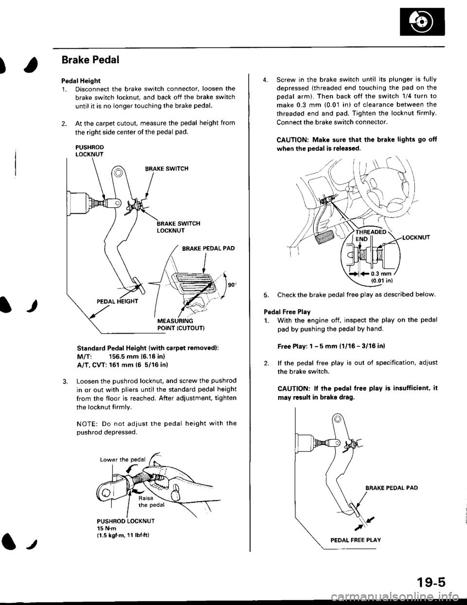
Brake Pedal
Pedal Height
1. Disconnect the brake switch connector, loosen the
brake switch locknut, and back off the brake switch
until it is no longer touching the brake pedal,
2. At the carpet cutout, measure the pedal height from
the right side center of the pedal pad.
PUSHRODLOCKNUT
Standard Pedal Height (with carpet removed):
M/T: 156.5 mm 16.16 inl
A/T, CVT: 161 mm (5 5/16 in)
3. Loosen the pushrod locknut, and screw the pushrod
in or out with pliers until the standard pedal height
from the floor is reached. After adjustment, tighten
the locknut firmly.
NOTE: Do not adiust the pedal height with the
Dushrod depressed.
It
PUSHROO LOCKNUT15 N.m(1.5 kgf.m. 11 lbI.ft)
POINT ICUTOUTI
4. Screw in the brake switch until its plunger is fully
depressed (threaded end touching the pad on the
pedal arm). Then back off the switch 1/4 turn to
make 0.3 mm (0.01 in) of clearance between the
threaded end and pad. Tighten the locknut firmly.
Connect the brake switch connector.
CAUTION: Make sure that the brake lights go off
when the pedal is released.
LOCKNUT
5. Check the brake pedal free play as described below.
Pedal Free Plsy
1. With the engine off, inspect the play on the pedal
pad by pushing the pedal by hand.
Free Play: 1 - 5 mm (1/16 - 3/16 inl
2. lf the pedal free play is out of specitication, adjust
the brake switch.
CAUTION: lf the pedal free play is insufficient, it
may result in brake drag.
BRAKE PEDAL PAO
)
19-5
*0.3 mm(0.01 in)
Page 1160 of 2189
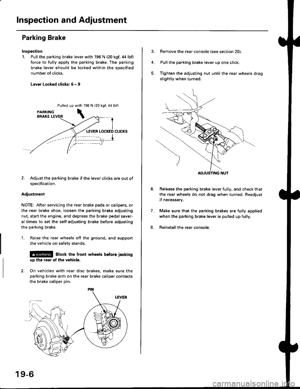
Inspection and Adjustment
Parking Brake
Inspection
1. Pull the parking brake lever with 196 N {20 kgf. 44 lbf)
force to fully apply the parking brake. The parking
brake lever should be locked within the sDecified
number of clicks.
Lever Locked clicks: 6 - I
Pulled up96 N 120 kgf,44lbf)
2. Adjust the parking brake if the lever clicks are out of
specification.
Adiusiment
NOTE: After servicing the rear brake pads or calipers, or
the rear brake shoe, loosen the parking brake adjusting
nut, start the engine, and depress the brake pedal sever-
al times to set the self-adjusting brake before adjusting
the parking brake.
1. Raise the rear wheels off the ground, and support
the vehicle on safety stands.
l@ Elock the front wheels bofore iackinguD the rear ot the v6hicle.
2. On vehicles with rear disc brakes, make sure theparking brake arm on the rear brake caliper contacts
the brake calioer Din.
with 1
\
19-6
Remove the rear console (see section 20).
Pullthe parking brake lever up one click,
Tighten the adjusting nut until the rear wheels drag
slightly when turned.
Belease the parking brake lever fully, and check that
the rear wheels do not drag when turned. Readjust
if necessarv.
Make sure that the parking brakes are fully applied
when the parking brake lever is pulled up fully.
Reinstall the rear console.
7.
8.
ADJUSTING NUT
Page 1175 of 2189
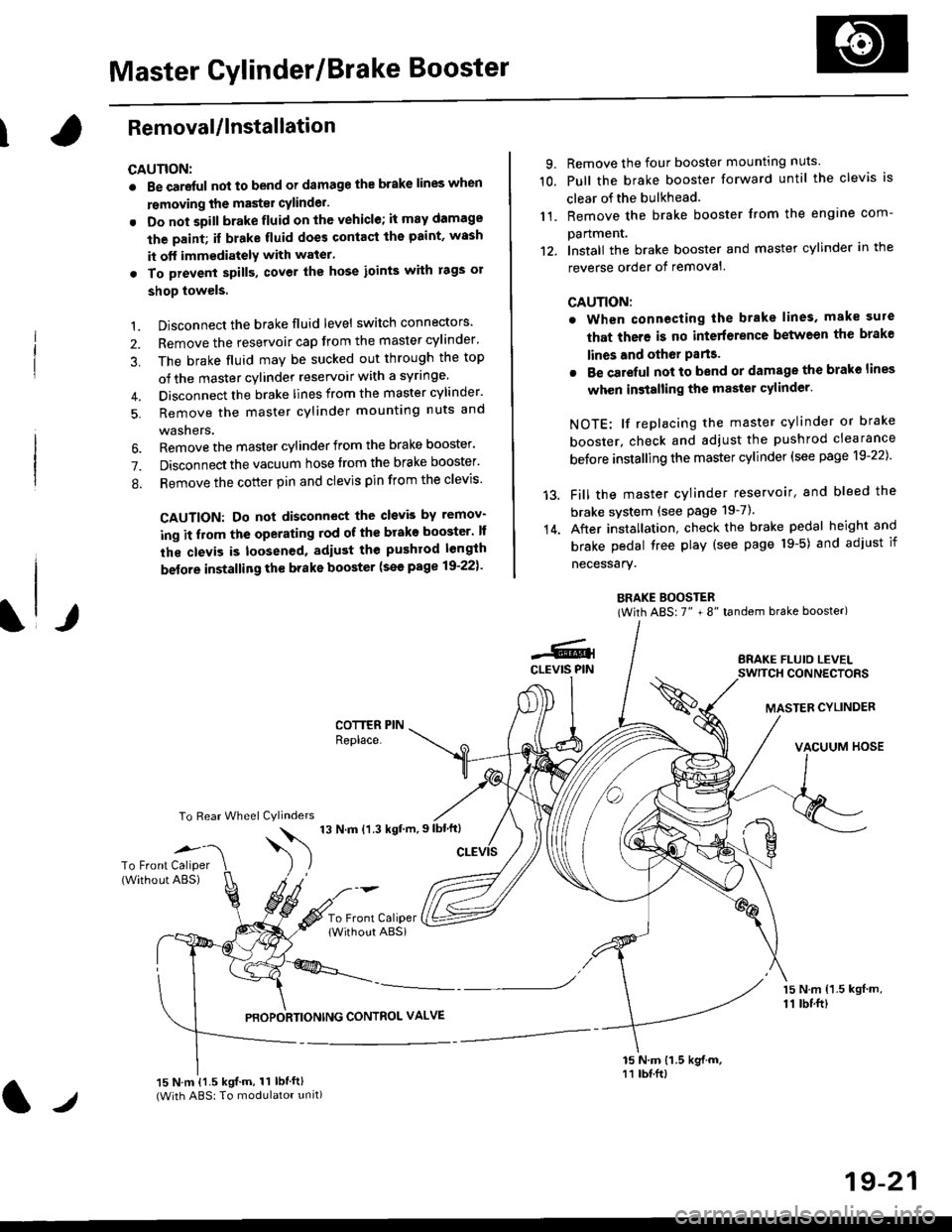
Master Cylinder/Brake Booster
IRemovaUlnstallation
CAUTION:
. Be care{ul nol to bend or damage the brake lines when
rsmoving the mastsr cYlinder.
. Do not soill brakefluid on the vehicle; it may damage
the paint; if brake fluid does contact the paint, wssh
it off immediatelY with water'
. To prevent spill3, cover the hose ioints with rags or
shop towels.
9. Remove the four booster mountlng nuts
10. Pull the brake booster forward until the clevis is
clear of the bulkhead.
11. Remove the brake booster from the engine com-
panmenr.'12. Install the brake booster and master cylinder in the
reverse order of removal.
CAUTION:
. When connecting the brake lines. make sure
that there is no inte erence between the brake
lines and oth6r Parts.
r Be careful not to bend or damage the brake lines
when installing the master cylinder.
NOTE: lf replacing the master cylinder or brake
booster, check and adiust the pushrod clearance
be{ore installing the master cylinder (see page 19-221'
Fill the master cylinder reservoir, and bleed the
brake svstem (see Page 19-7).
After installation. check the brake pedal height and
brake pedal tree play (see page l9-5) and adjust if
necessary.
BRAKE BOOSTER(With ABS: 7" + 8" tandem brake booster)
BRAKE FLUIO LEVELSWITCH CONNECTORS
MASTER CYLINDER
VACUUM HOSE
1.
2.
3,
5.
Disconnect the brake fluid level switch connectors'
Remove the reservoir cap from the master cylinder'
The brake fluid may be sucked out through the top
of the master cylinder reservoir with a syrlnge.
Disconnect the brake lines from the master cylinder'
Remove the master cylinder mounting nuts and
washers.
\l/
6. Remove the master cylinder from the brake booster'
7. Disconnect the vacuum hose trom the brake booster'
8. Remove the cotter pin and clevis pin from the clevis'
CAUTION: Do not disconnect the clevb by remov-
ing it from the operating rod of the brako booster' lf
the clevis is loosened, adiust the pushrod length
before installing th€ brake booster (see page 19-221'
COTTER PINReplace.
To Rear Wheel Cylinders
14.
-6.4CLEVIS PIN
To Front Caliper(Without ABS)$
t'N't'ttrnt'-''
To Front CaliperlWithout ABSi
PBOPORTIONING CONTROL VALVE
15 N.m {1.5 kgl m,11 tbtft)
15 N.m {1.5 kgif.m, 11 lbtft}(With ABS: To modulator unit)lr
19-21
Page 1176 of 2189
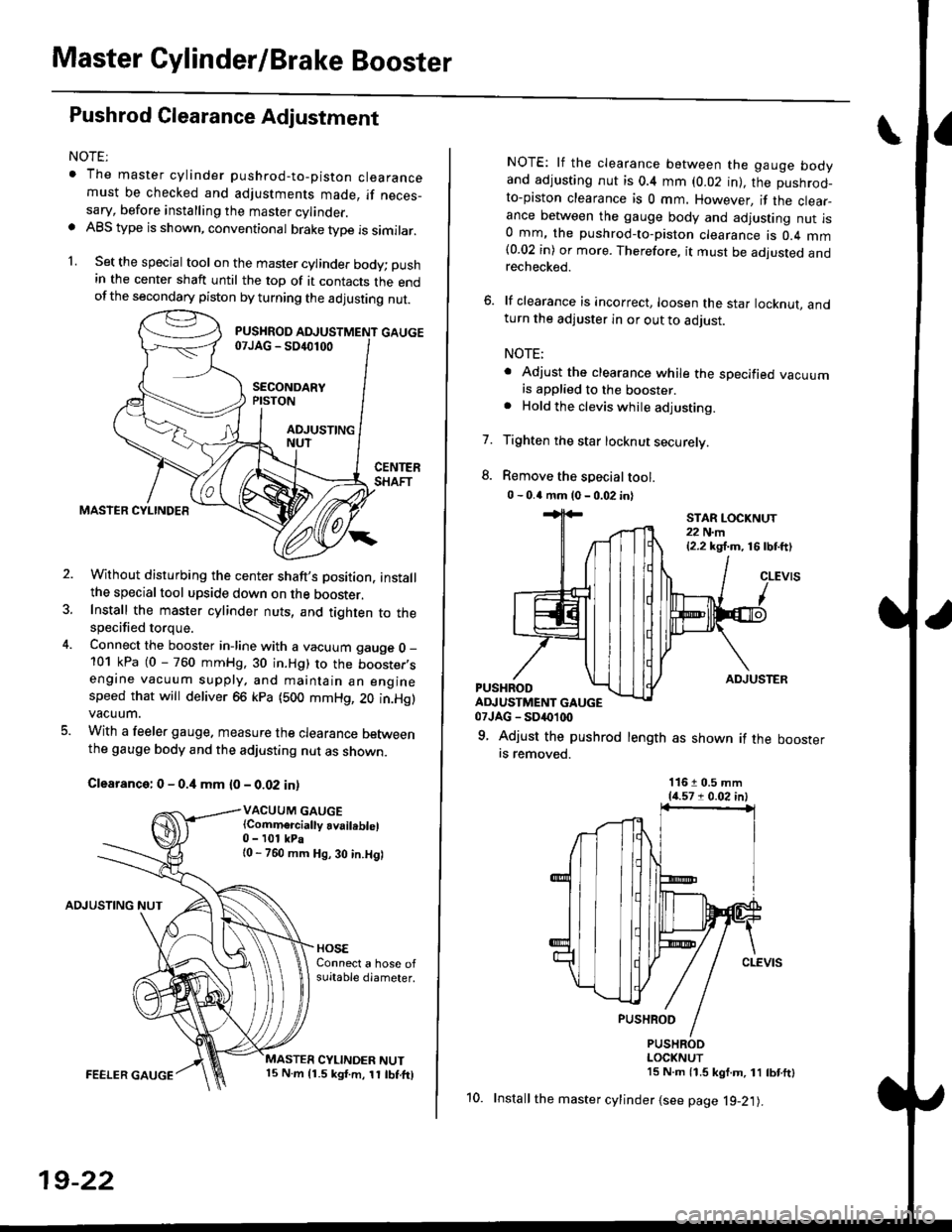
Master Cylinder/Brake Booster
Pushrod Glearance Adjustment
NOTEr
. The master cylinder pushrod-to-piston clearancemust be checked and adjustments made, if neces_sary, before installing the master cylinder.. ABS type is shown, conventional brake type is similar.
1. Set the special tool on the master cylinde. body; push
in the center shaft until the top of it contacts the endofthe secondary piston by turning the adjusting nut.
Without disturbing the center shaft's Dosition, installthe specialtool upside down on the booster.Install the master cylinder nuts, and tighten to thespecified torque.
Connect the booster in-line with a vacuum gauge O _
101 kPa (0 - 760 mmHg, 30 in.Hg) to the booster,sengine vacuum supply, and maintain an enginespeed that will deliver 66 kpa (500 mmHg, 20 in.Hg)vacuum.
With a feeler gauge. measure the clearance Detweenthe gauge body and the adjusting nut as shown.
Clearance: 0 - 0.4 mm {0 - 0.02 in)
VACUUM GAUGE(Comm€rcially availeblel0 - 101 kPa{0 - 760 mm Hg, 30 in.Hg)
AOJUSTING NUT
FEELER GAUGE
19-22
10.
NOTE: lf the clearance between the gauge bodyand adjusting nut is 0.4 mm (0.02 in), the pushrod-to-piston clearance is 0 mm. However, if the clear_ance between the gauge body and adjusting nut is0 mm, the pushrod-to-piston clearance is 0.4 mm(0.02 in) or more. Therefore, it must be adjusted andrechecked.
6. lf clearance is incorrect, loosen the star locknut, andturn the adjuster in or out to adjust.
NOTE;
. Adjust the clearance while the specified vacuumis applied to the booster.. Hold the clevis while adjusting.
Tighten the star locknut securely.
Remove the special tool.
0 - 0.4 mm (0 - 0.02 in)
7.
ADJUSTERPUSHRODADJUSTMENT GAUGE07JAG - SD('1(x)
9. Adjust the pushrod length as shown if the boosterrs removed.
STAR LOCKNUT22 N.m{2.2 kg,f.m, 16lbtft)
11610.5 mm{{.571 0.02 in)
PUSHRODLOCKNUT15 N.m 11.5 kgf.m, 11 tbtftl
Install the master cylinder {see page l9-21).