2000 HONDA CIVIC lock
[x] Cancel search: lockPage 1090 of 2189
lnspection and Adjustment
Pump Pressure Check
Check the fluid pressure as follows to determine
whether the trouble is in the pump or gearbox.
NOTE: First check the power steering fluid level andpump belt tension.
CAUTION: Disconnect the high pr$sure hos€ with care
so as not lo spill the power sieering tluid on tha frame
and other parts.
1. Disconnect the outlet line from the Dumo outlet fit-
ting, then installthe P/S joint adaptor (pump) on the
Dumo outlet.
2. Connect the P/S joint adaptor (hose) to the power
steering pressure gauge, then connect the outlet
hose to the adaptor.
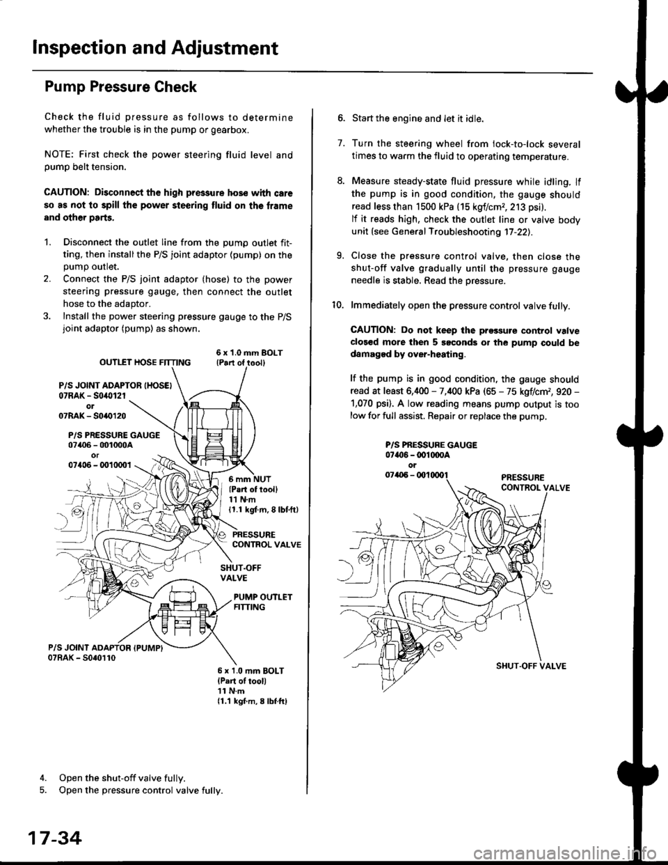
3. Install the power steering pressure gauge to the P/Sjoint adaptor (pump) as shown.
ourlEr HosE FnrNo ,t"ll lrilu"ott
P/S JOINT ADAPTOB IHOSEI07RAK - S0i10l2rol07RAK- 50{{)120
P/S PRESSURE GAUGE07406 - 001000Aor07406 - 0010001
4. Open the shut-off valve fully.
5. Open the pressure control valve fully.
17-34
(Pa.t of tooll11 N.m11.1 kgt m, 8 lbf.ftl
PRESSURECONTROL VALVE
SHUT.OFFVALVE
PUMP OUTLETFITTING
6 x 1.0 mm BOLTlPart of tool)11 N.m11.1 kgf m, 8 lbtftl
7.
Start the engine and let it idle.
Turn the steering wheel from lock-to-lock several
times to warm the fluid to operating temperature.
Measure steady-state fluid pressure while idling. If
the pump is in good condition, the gauge should
read less than 1500 kPa (15 kgf/cmr, 213 psi).
lf it reads high, check the outlet line or valve body
unit (see General Troubleshooting 17-22).
Close the pressure control valve, then close the
shut-off valve gradually until the pressure gauge
needle is stable. Read the oressure.
lmmediately open the pressure control valve fully.
GAUTION: Do not keep lhe prossure control valve
clos€d more then 5 soconds or the pump could be
damagod by over-heating.
lf the pump is in good condition, the gauge should
read at least 6,400 - 7,400 kPa (65 - 75 kgflcm,, 920 -
1,070 psi). A low reading means pump output is too
low for full assist. Repair or replace the pump,
9.
P/S PBESSURE GAUGE07{16 -@1@OA
oi
SI{UT.OFF VALVE
Page 1091 of 2189
Steering Wheel
l,/
Removal
SRS components are located in this area Review the
SRS component locations, precautions, and procedures
in the SRS section (24) before performing repairs or ser-
vice.
NOTE: Before removing the steering wheel. align the
front wheels straight ahead.
1. Remove the driver's airbag assembly from the
steering wheel (see section 24)
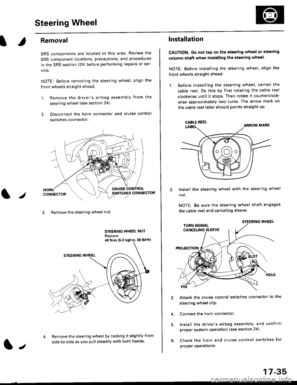
2. Disconnect the horn connector and cruise control
switches connector.
CRUISESWITCHES CONNECTOR
3. Remove the steering wheel nut
STEERING WHEEL NUT
Replace.
Remove the steering wheel by rocking it slightly from
side-to-side as you pull steadily with both hands.
ag N.m {5.0 kgt rn, 36lbfft)
1.,
17-35
lnstallation
CAUTION: Do not tap on the steering wheel or steering
column shaft when installing the stsering wheel.
NOTE: Before installing the steering wheel, align the
front wheels straight ahead.
1. Before installing the steering wheel, center the
cable reel, Do this by first rotating the cable reel
clockwise until it stops. Then rotate it counterclock-
wise approximately two turns The arrow mark on
the cable reel label should points straight up.
Install the steering wheel with the steering wheel
nut.
NOTE: Be sure the steering wheel shaft engages
the cable reel and canceling sleeve.
Attach the cruise control switches connector io the
steering wheel cliP,
Connect the horn connector.
Install the driver's airbag assembly, and confirm
proper system operation (see section 24).
Check the horn and cruise control switches for
proper operatrons.
CAELE REEL
Page 1094 of 2189
Steering Column
Inspection
NOTE: The tilt steering column type is shown; the con-
ventional steering column is similar except for the tilt
mechantsm.
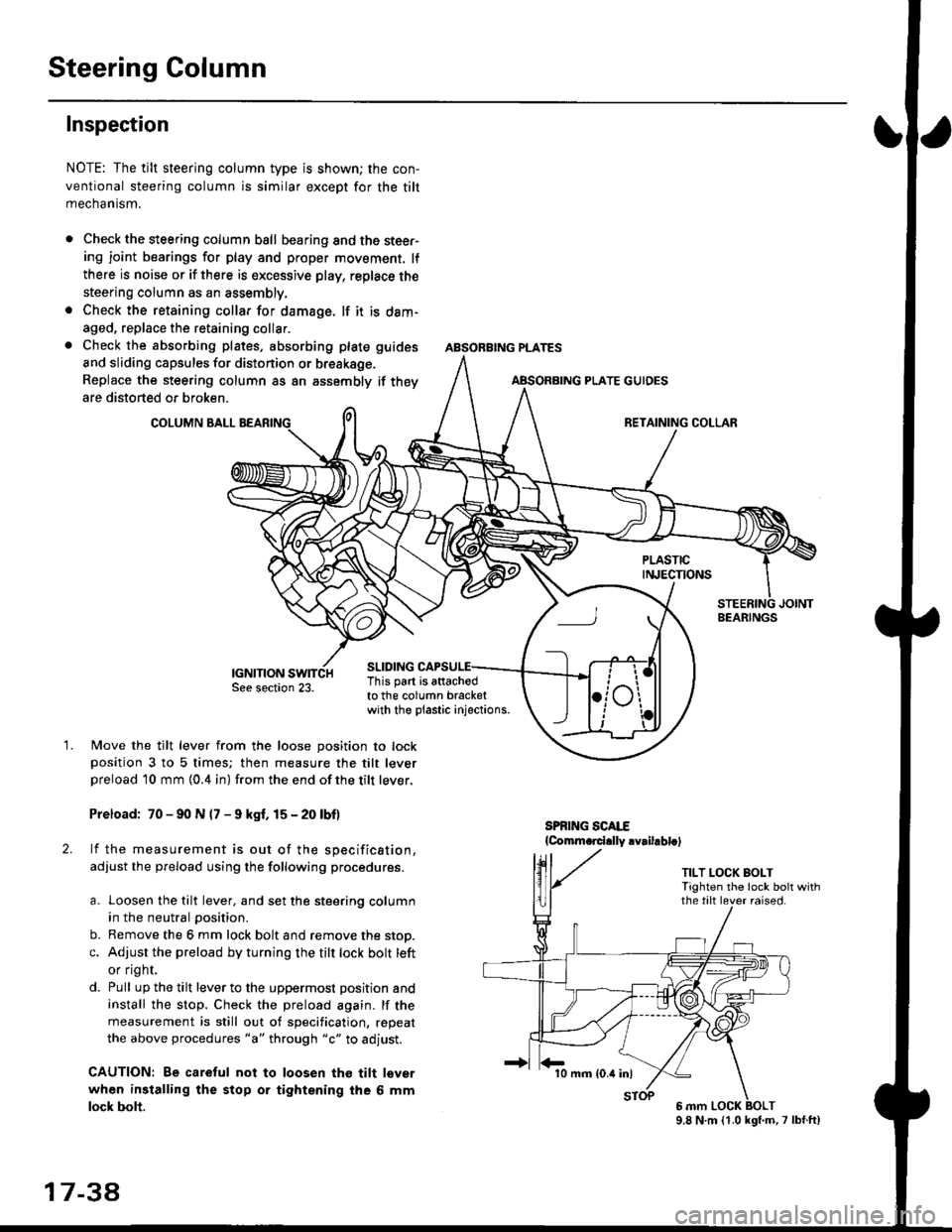
Check the steering column ball bearing and the steer-ing joint bearings for play and proper movement. lf
there is noise or if there is excessive play, replace the
steering column as an assembly.
Check the retaining collar for damage. lf it is dam-
aged, replace the retaining collar.
Check the absorbing plates, absorbing plate
and sliding capsules for distonion or breakage.
Replace the steering column as an assembly
are distorted or broken.
COLUMN BALL
ABSORBING PLATE GUIDES
guides
if they
SLIDING
BEARINGS
TILT LOCK BOLTTighten the lock bolt withthe tilt lever raised.
This part is attachodto the column bracketwith the plastic injections.
1.Move the tilt lever from the loose position to lockposition 3 to 5 times; then measure the tilt leverpreload l0 mm {0.4 in) from the end ofthe tilt lever.
Preload: 70 - 90 N (7 - 9 kgf. 15 - 20 lbf)
lf the measurement is out of the specification,
adjust the pfeload using the following procedures.
a. Loosen the tilt lever, and set the steering column
in the neutral position.
b. Remove the 6 mm lock bolt and remove the stop.
c. Adjust the preload by turning the tilt lock bolt left
or flgnr.
d. Pull up the tilt lever to the uppermost position and
install the stop. Check the preload again. lf the
measurement is still out of specification, repeat
the above procedures "a" through "c" to adjust.
CAUTION: Be caretul not to loosen tho tilt lever
when installing the stop or tightening the 6 mm
lock bolt.
17 3a
10 mm (0.4 inl
9.8 N.m (1.0 kgl.m,7 lbf.ft)
Page 1105 of 2189
)
Disassembly
t)
Steering Rack DisassemblY
NOTE:
r Before disassemble the gearbox, wash it off with sol
vent and a brush.
. Do not dip seals and O-rings in solvent.
1. Remove the steering gearbox (see page 17-47]..
2. Remove the tie-rod end and locknut.
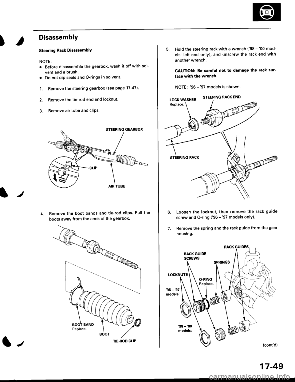
3. Remove air tube and cliPs.
Remove the boot bands and tie-rod clips Pull the
boots away from the ends of the gearbox.
BOOT
(|-,TIE.ROD CLIP
Hold the steering rack with a wrench ('98 -'00 mod-
els: left end only), and unscrew the rack end with
another wrench.
CAUTION: Be caroful not to damage the rack 3ur-
faco whh the wrench.
NOTE: '96 -'97 models is shown.
STEERING RACK END
STEERING RACK
Loosen the locknut, then remove the rack guide
screw and O-ring ('96 -'97 models only)
Remove the spring and the rack guide from the gear
housing.
7.
{cont'd}
17 -49
LOCK WASHER
Page 1119 of 2189
)
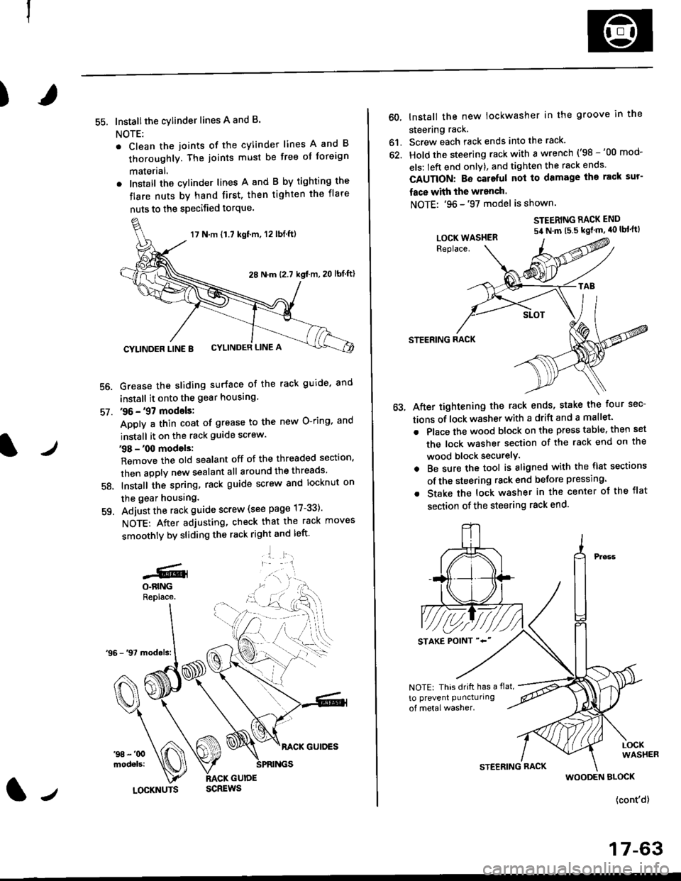
55. Installthe cylinder lines A and B.
NOTE:
. Clean the joints of the cylinder lines A and B
thoroughly. The joints must be free of foreign
materlal.
. Install the cylinder lines A and B by tighting the
flare nuts by hand first, then tighten the flare
nuts to the specified torque.
56.
57.
Grease the sliding surface of the rack guide, and
install it onto the gear housing
36 - '97 models:
Apply a thin coat of grease to the new O-ring, and
install it on the rack guide screw.
38 - '00 models:
Remove the old sealant off of the threaded section,
then apply new sealant all around the threads
Install the spring, rack guide screw and locknut on
the gear housing.
Adjust the rack guide screw (see page 17-33)'
NOTE: After adjusting, check that the rack moves
smoothly by sliding the rack right and left'
'1 l:.r1
58.
-GlO.BINGReplace.
17 N.m {1.7 kgt'm, 12 lbl.ft)
28 N.m (2.7 kgf m,20 lbf ftl
CYLINDER LINE 8 CYLINDER LINE A
l/LOCKNUTS
60, lnstall the new lockwasher in the groove in the
steering rack.
61. Screw each rack ends into the rack'
62. Hold the steering rack with a wrench ('98 -'00 mod-
els: left end onlY), and tighten the rack ends'
CAUTION: Bo cateful nol to damage ihe rack sur-
face with the wranch.
NOTE: '96 -'97 model is shown.
STEERING RACK END
54 N'm t5 5 kgt m' 40 lbl'ft)
STEERING RACK
After tightening the rack ends, stake the four sec-
tions of lock washer with a drift and a mallet.
Place the wood block on the press table. then set
the lock washer section of the rack end on the
wood block securelY.
Be sure the tool is aligned with the flst sections
of the steering rack end belore pressing.
Stake the lock washer in the center ot the flat
section of the steering rack end.
LOCK WASHER
NOTE: This drift has a flat,
to prevent puncturing
WOODEN BLOCK
{cont'd}
17-63
Page 1120 of 2189
Steering Gearbox
Reassembly (cont'dl
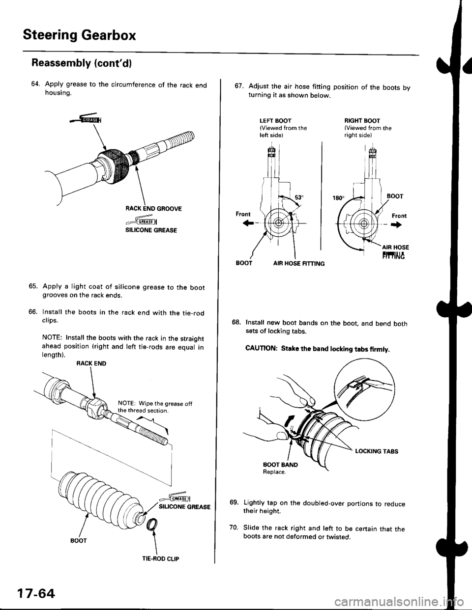
64. Apply grease to the circumference of the rack endhousing.
RACK END GROOVE
=^.#-q!:s!!H
SILICONE GREASE
Apply a light coat of silicone grease to the bootgrooves on the rack ends.
lnstall the boots in the rack end with the tie-rodclips.
NOTE: Install the boots with the rack in the straightahead position (right and left tie-rods are equal inlength).
66.
RACK END
NOTE: Wipe the grease offthe thread section.
17-64
TIE.ROD CLIP
67. Adjust the air hose fitting position of the boots bvturning it as shown below.
LEFT BOOT(Viewed from theleft side)
RIGHT BOOT{Viewed from theright side)
AIR HOSE FITTING
Install new boot bands on the boot, and bend bothsets of locking tabs.
CAUTION: Stlke ths band locking tabs firmly.
Lightly tap on the doubled-over portions to reducetheir height.
Slide the rack right and left to be certain that theboots are not deformed or twisted.
Page 1122 of 2189
Steering Gearbox
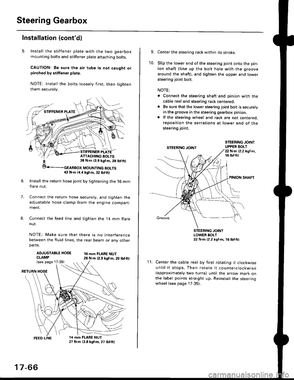
Installation (cont'dl
5. Install the stiffener plate with the two gearbox
mounting bolts and stiffener plate aftaching bolts.
CAUTION: Be sure the air tube is not caught orpinched by stiffener plate,
NOTE: Install the bolts loosely first, then tighten
them securely.
7.
8.
6.Install the return hose joint by tightening the l6 mm
flare nut.
Connect the relurn hose securely, and tighten the
adjustable hose clamp from the engine compart-ment.
Connect the feed line and tighten the 14 mm flare
nut.
NOTE: Make sure that there is no interference
between the fluid lines, the rear beam or any otherparts.
ADJUSTABLE HOSECLAMP(see page 17-39)
16 mm FLARE NUT28 N.m {2.9 ksl.m. 20 lbf.ft)
RETURN
1a mm FLARE NUT37 N.m (3.8 kg{.m, 27 lbt.ftl
ATTACHING AOLTS38 N.m 13.9 kgf.m, 28 lbf.ftl
MOUNTING BOLTS(} N.m (4.a kgt m, 32 lbf.ftl
17-66
9.Center the steering rack within its stroke.
Slip the lower end of the steering joint onto the pin-
ion shaft (line up the bolt hole with the groove
around the shaft), and tighten the upper and lower
steering joint bolt.
NOTE:
. Connect the steering shaft and pinion with the
cable reel and steering rack centered.. Be sure that the lower steering joint bolt is securely
in the groove in the steering gearbox pinion.
. lf the steering wheel and rack are not centered,
reposition the serrations at lower end of the
steering joint.
10.
STEERING JOINTUPPER BOLT22 N.m (2.2 kgf.m,16 tbt.ftl
PINION SHAFT
Groove,
STEERING JOINTLOWER BOLT22 N.m (2.2 kgt.m, 16lbtttl
11.Center the cable reel by first rotating it clockwise
until it stops. Then rotate it counterclockwise(approximately two turns) until the arrow mark onthe label points straight up. Reinstall the steeringwheel (see page 17 35).
Page 1123 of 2189
)
1?
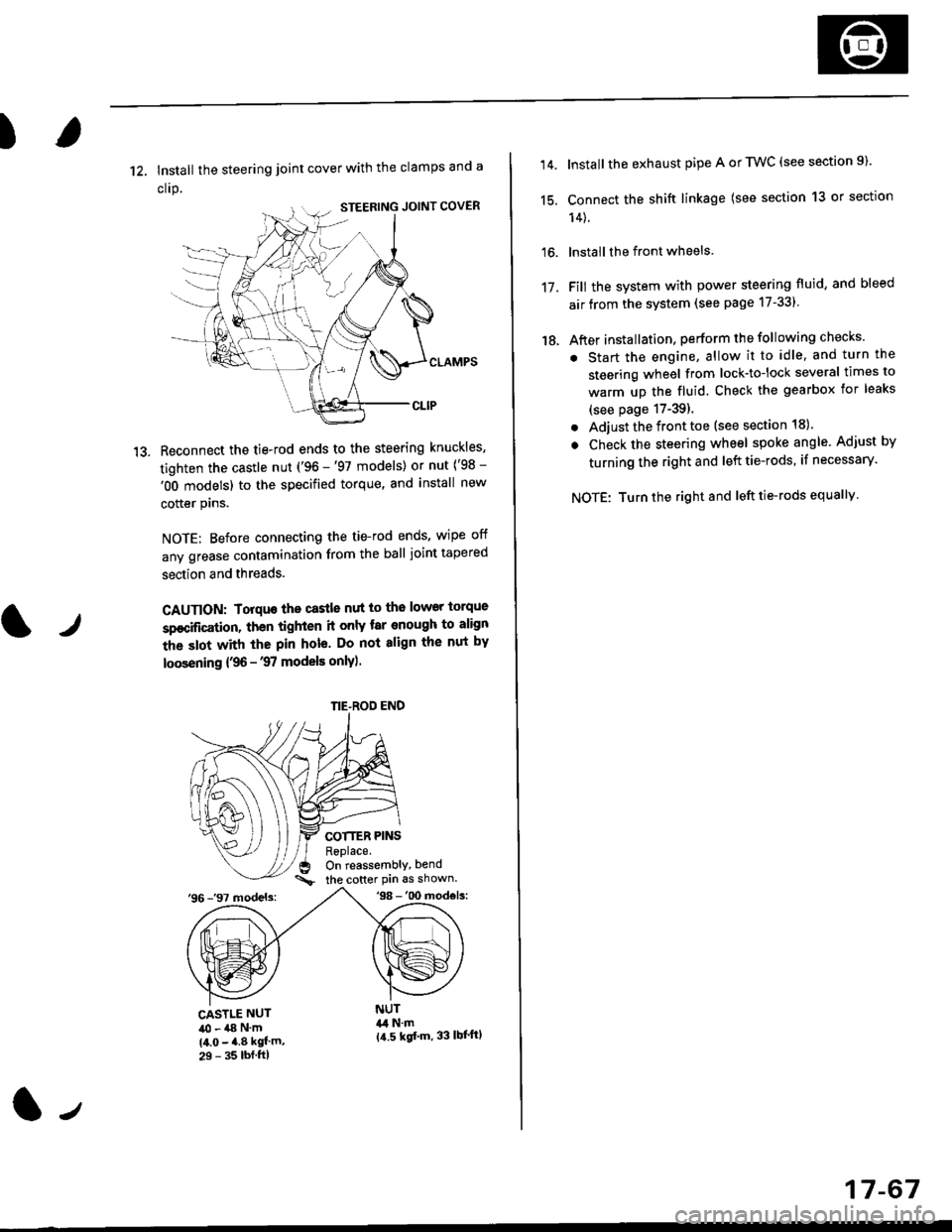
12, Install the steering joint cover with the clamps and a
clrp.
Reconnect the tie-rod ends to the steering knuckles,
tighten the castle nut ('96 -'97 models) or nut ('98 -
'OO models) to the specified torque, and install new
cotter plns.
NOTE: Before connecting the tie-rod ends, wipe off
any grease contamination from the ball joint tapered
section and threads.
CAUTION: Torquo the castle nut to the lower torque
sp€cification, then tighten it only tar enough to align
the slot with the pin hole. Do not align the nut by
loosening {,96 -'97 models only).
COTTER PINSReplace.On reassembly, bend
the cotter Pin 6s shown.'96 -'97 models:'98 -'00 mod€ls:
tr
CASTLE NUT40 - a8 N'm(4.0 - 4.8 kgf'm,29 - 35 lbf.ftl
NUT&l N.m{a.5 kgf'm, 33 lbl'ftl
NE-ROD END
(l-,
17-67
14.
15.
16.
17.
18.
Install the exhaust pipe A or TWC (see section 9).
Connect the shift linkage (see section 13 or section
14).
lnstall the front wheels
Fill the system with power steering fluid, and bleed
air from the system (see page 17-331
After installation, perform the following checks
. Start the engine, allow it to idle, and turn the
steering wheel from lock-tolock several times to
warm up the fluid. Check the gearbox for leaks
(see page 17-39).
. Adjust the front toe (see section 18).
. Check the steering wheel spoke angle. Adjust by
turning the right and left tie-rods, if necessary.
NOTE: Turn the right and left tie-rods equallv