Page 1176 of 2189
Master Cylinder/Brake Booster
Pushrod Glearance Adjustment
NOTEr
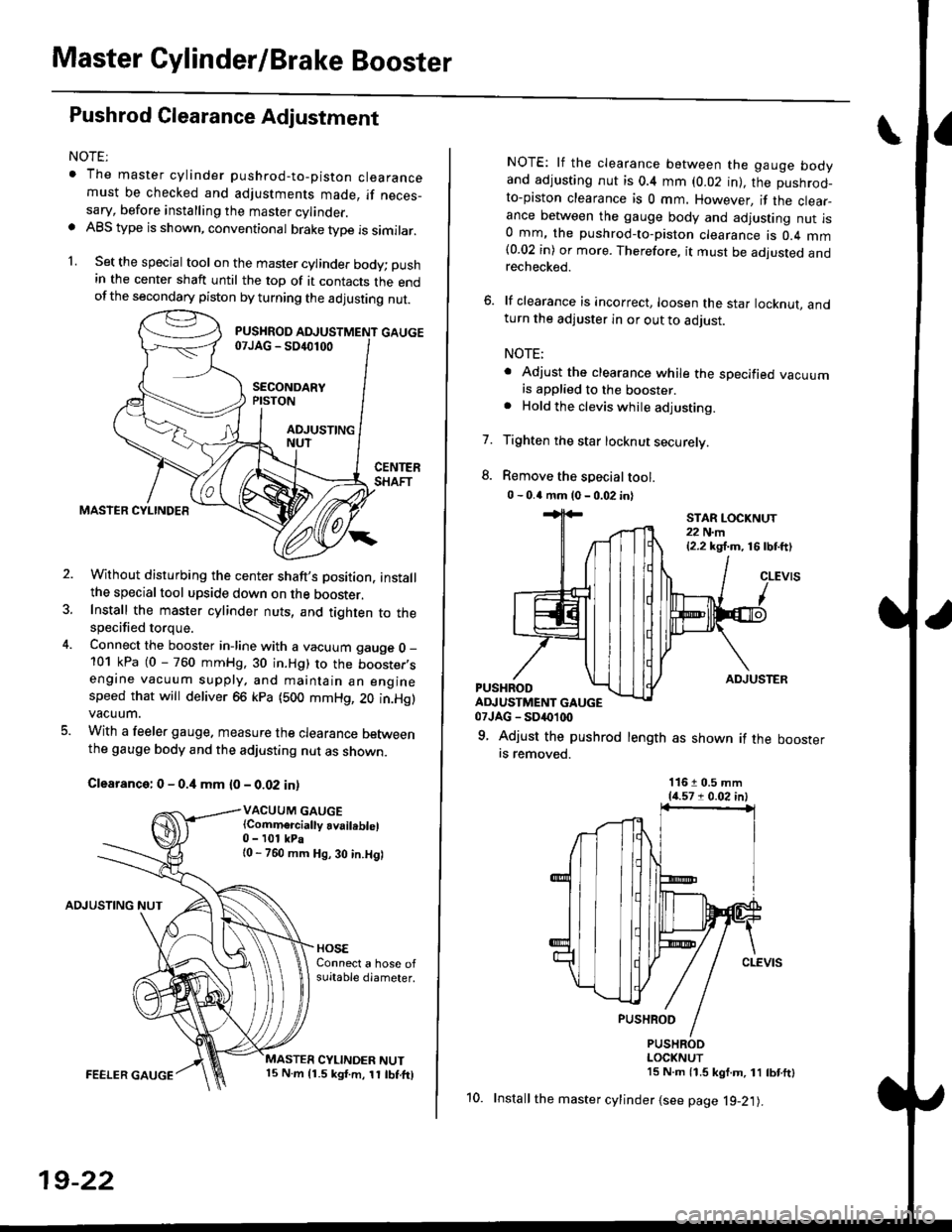
. The master cylinder pushrod-to-piston clearancemust be checked and adjustments made, if neces_sary, before installing the master cylinder.. ABS type is shown, conventional brake type is similar.
1. Set the special tool on the master cylinde. body; push
in the center shaft until the top of it contacts the endofthe secondary piston by turning the adjusting nut.
Without disturbing the center shaft's Dosition, installthe specialtool upside down on the booster.Install the master cylinder nuts, and tighten to thespecified torque.
Connect the booster in-line with a vacuum gauge O _
101 kPa (0 - 760 mmHg, 30 in.Hg) to the booster,sengine vacuum supply, and maintain an enginespeed that will deliver 66 kpa (500 mmHg, 20 in.Hg)vacuum.
With a feeler gauge. measure the clearance Detweenthe gauge body and the adjusting nut as shown.
Clearance: 0 - 0.4 mm {0 - 0.02 in)
VACUUM GAUGE(Comm€rcially availeblel0 - 101 kPa{0 - 760 mm Hg, 30 in.Hg)
AOJUSTING NUT
FEELER GAUGE
19-22
10.
NOTE: lf the clearance between the gauge bodyand adjusting nut is 0.4 mm (0.02 in), the pushrod-to-piston clearance is 0 mm. However, if the clear_ance between the gauge body and adjusting nut is0 mm, the pushrod-to-piston clearance is 0.4 mm(0.02 in) or more. Therefore, it must be adjusted andrechecked.
6. lf clearance is incorrect, loosen the star locknut, andturn the adjuster in or out to adjust.
NOTE;
. Adjust the clearance while the specified vacuumis applied to the booster.. Hold the clevis while adjusting.
Tighten the star locknut securely.
Remove the special tool.
0 - 0.4 mm (0 - 0.02 in)
7.
ADJUSTERPUSHRODADJUSTMENT GAUGE07JAG - SD('1(x)
9. Adjust the pushrod length as shown if the boosterrs removed.
STAR LOCKNUT22 N.m{2.2 kg,f.m, 16lbtft)
11610.5 mm{{.571 0.02 in)
PUSHRODLOCKNUT15 N.m 11.5 kgf.m, 11 tbtftl
Install the master cylinder {see page l9-21).
Page 1179 of 2189
I
7.
11.
Clean the caliper thoroughly; remove any rust, and
check for grooves and cracks.
Check the brake disc for damage and cracks.
lvlake sure that the pad retainers are installed in
their correct positions.
PAD RETAINERS
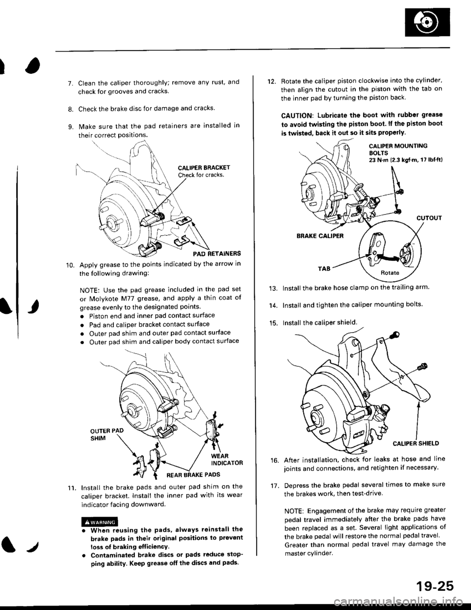
Apply grease to the points indicated by the arrow in
the following drawing:
NOTE: Use the pad grease included in the pad set
or lMolykote M77 grease, and apply a thin coat of
grease evenly to the designated points.
. Piston end and inner pad contact surface
. Pad and caliper bracket contact surface
. Outer pad shim and outer pad contact surface
. Outer pad shim and caliper body contact surface
lnstall the brake pads and outer pad shim on the
caliper bracket. Install the inner pad with its wear
indicator facing downward.
@iwhen reusing the pads, always reinstall the
brake pads in iheil original posiiions lo prevont
loss ol braking efficiency
. Contaminaled brake discs or pads reduce stop-
ping ability. Keep grease off the discs and pads.
t./
19-25
12. Rotate the caliper piston clockwise into the cylinder'
then align the cutout in the piston with the tab on
the inner pad by turning the piston back
CAUTION: Lubricate ths boot with rubber grease
to avoid twisting the piston boot. lf the piston boot
is twisted, back it out so it sits properly.
CALIP€R MOUNTINGBOLTS23 N,m {2.3 kg{.m, 17 lbt'ft)
13.
14.
15.
CUTOUT
BRAKE CALIPER
Install the brake hose clamp on the trailing arm.
Install and tighten the caliper mounting bolts.
Install the caliper shield.
After installation. check for leaks at hose and line
joints and connections, and retighten if necessary.
Depress the brake pedal several times to make sure
the brakes work, then test-drive
NOTE: Engagement of the brake may requrre greater
pedal travel immediately after the brake pads have
been replaced as a set. Several light applications of
the brake pedal will restore the normal pedal travel.
Greater than normal pedal travel may damage the
master cylinder.
16.
17.
Page 1181 of 2189
Rear Brake Caliper
Disassembly
@f l',lever use an air hose or dry brush to clean
assemblies.
. Use an OsHA-approved vacuum cleaner to
brake
avoid
breathing brake dust.
. Contaminated brake discs or pads reduce stopping
ability.
CAUTION:
. Do not spill brake tluid on the cal; h may damage the
paint; if brake fluid does contact the paint, wash ii
ofl immediatelY with water.
. To prevent spills, cover the hose ioints whh rags or
shop tow€ls.
. Clean all parts in brake fluid and air dry; blow out all
passagss with complessed air.
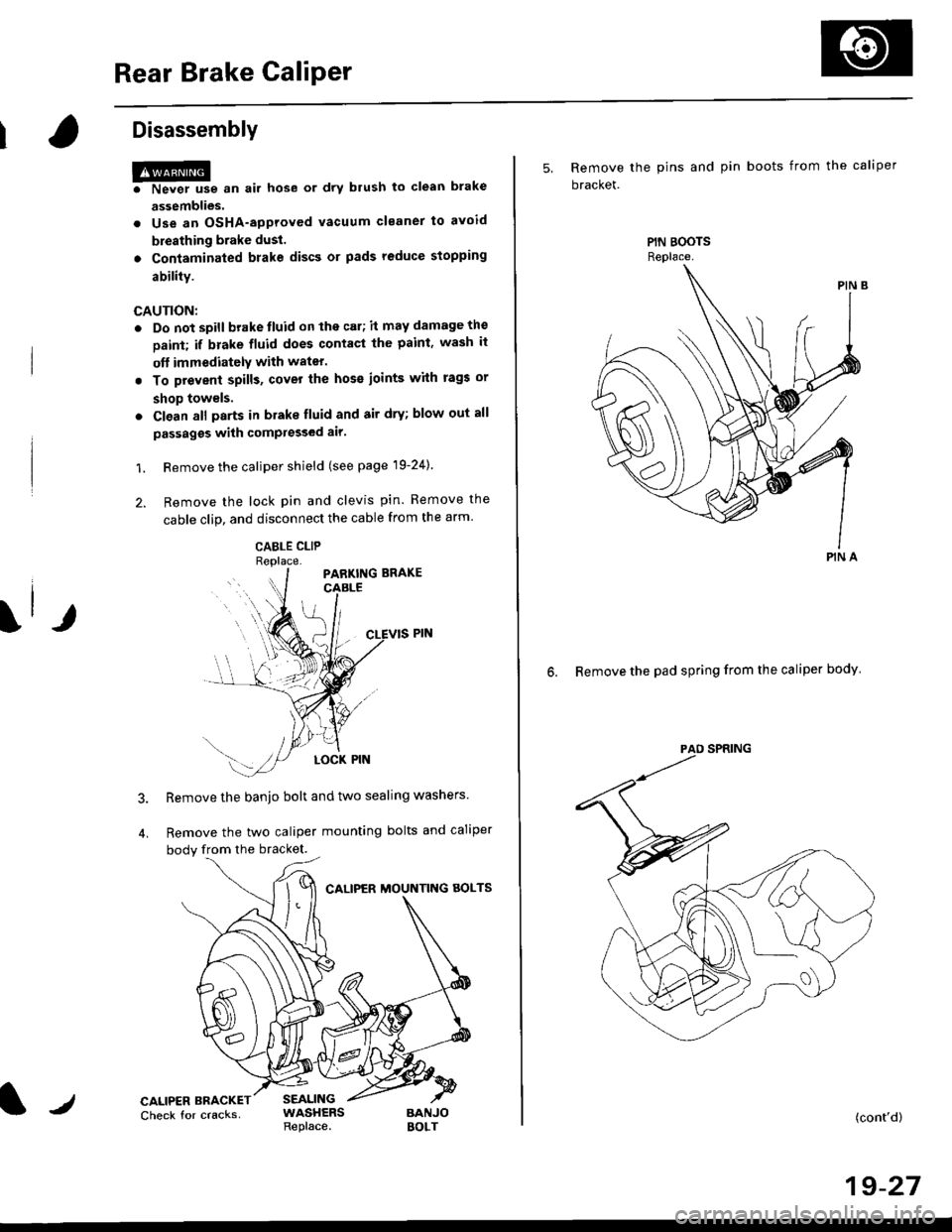
1. Remove the caliper shield (see page 19-24).
2. Remove the lock pin and clevis pin. Remove the
cable clip, and disconnect the cable from the arm
CABLE CLIP
Remove the banjo bolt and two sealing washers
Remove the two caliper mounting bolts and caliper
body from the bracket.
CALIPER MOUNTNG AOLTS
CALIPER BRACKETCheck for cracksSEALINGWASHERSReplace.BANJOBOLT
5, Remove the pins and pin boots from the caliper
bracket.
6. Remove the pad spring from the caliper body
PIN A
(cont'd)
19-27
Page 1182 of 2189
Rear Brake Galiper
Disassembly (cont'd)
7. Remove the piston by rotating the piston counter-clockwise with the tool, and remove the piston
boot.
CAUTION: Avoid damaging the piston.
PISTON BOOTReplace.
Remove the piston seal.
CAUTION: Take care not to damage the cylinderbore.
CALIPER BODYCheck for scoring on
9. Install the special tool between the caliper bodv andspnng cover.
CAUTION: Be caretul not to damags the inside ofthe caliper cylinder during caliper disassembty.
BRAKE SPRINGCOMPRESSOR07HAE - SG00100
11.
LOCKNUTS
Position the locknuts as shown. then turn the shaftuntil the plate just contacts the caliper body.
NOTE: Do not compress the spring under thespring cover.
Turn the shaft clockwise 1/4 -'ll2 tu.n to comoressadjusting spring B in the caliper body.
CAUTION: To preyant damage to the inner compo-nonts. do not turn the shaft mor€ than 1/2 turn.
SHAFT
LOCKNUTS
PISTON SEALReplace.
ADJUSTII{GSPRING 8
19-28
Page 1183 of 2189
\
13.
Lower the locknuts fully, and tighten them securely.
NOTE: Keep the locknuts in this position until you
reinstallthe circlip.
Remove the circlip with snap ring pliers.
SNAP RINGPLIERS07914 - SA50001
't 4.Hold the plate with your fingers, and turn the shaft
counterclockwise. Remove the special tool from the
calioer.
LOCKNUTS
l./
15. Remove the adjusting bolt.
Remove the spring cover, adjusting spring B, spacer,
bearing A, and cup from the adjusting bolt.
Remove the sleeve piston, and remove the pin from
the cam in the caliper body.
'17 .
SLEEVE PISTONCheck lor wear anddamage,
i
I
I
6-50-awl \
IO-RIITGRepl6ce.
(cont'd)
19-29
Page 1184 of 2189
Rear Brake Galiper
Disassembly (cont'dl
18. Remove the return spring.
PARKING LEVER/CAM ASSEMBLYCheck lor damage.
Remove the parking lever and cam as an assemblvfrom the caliper body.
CAUTION: Do not loosen the parking nut with thecam inslalled in the caliper body, lf the leyer andshaft must be separated, hold the lever in a vise,and loosen the parking nut,
Remove the cam boot.
RETURNSPRING
19.
19-30
Page 1186 of 2189
Rear Brake Caliper
Reassembly (cont'dl
L
PARKING NUT28 N.m (2.8 kgt m,20 rbr.trt
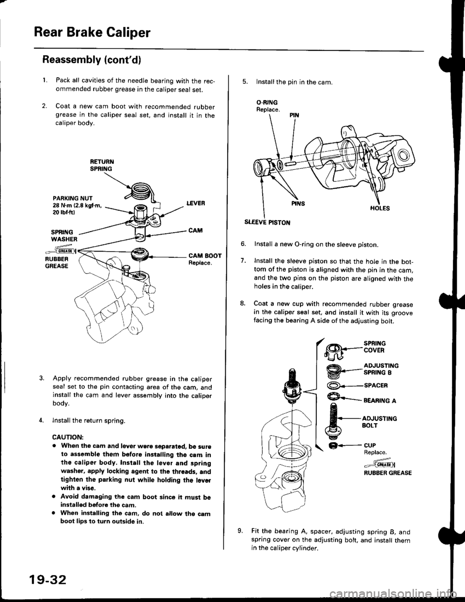
Pack all cavities of the needle bearing with the rec,
ommended rubber grease in the caliper seal set,
Coat a new cam boot with recommended rubbergrease in the caliper seal set, and install it in thecaliper body.
SPRII{GWASHEN
z..-_e!!!9!.{RUBBERGREASE
Apply recommended rubber grease in the caliperseal set to the pin contacting area of the cam, andinstall the cam and lever assembly into the caliperbodv.
lnstall the return spring.
CAUTION:
. When the cam and lever wgre separatod. b€ surgto assemble them bofore installing the cam inthe caliper body, Install the lev€r and spring
washer. apply locking agent to the threads, andtighten the parking nut while holding the l.vorwhh a vise,
. Avoid damaging the cam boot since it must bsinstalled before thg cam.. When installing the cam, do nol allow the camboot lips lo turn outside in.
19-32
5. Installthe pin in the cam.
O.RINGReplace.
SLEEVE PISTON
Install a new O-ring on the sleeve pisron.
Install the sleeve piston so that the hole in the bot-tom of the piston is aligned with the pin in the cam,and the two pins on the piston are aligned with theholes in the calioer.
Coat a new cup with recommended rubber grease
in the caliper seal set, and install it with its groove
facing the bearing A side of the adjusting bolt.
7.
€8.--:BTif
@'-.-3nfi""'i"
@--seacrn
$ eeenrne a
fi,*,*^"
GF-
Fit the bearing A, spacer. adjusting spring B, andspring cover on the adjusting bolt, and install themin the caliDer cvlinder.
CUPReplace.
=^.#-g!!!!!Jl
RUBBER GREASE
o
Page 1211 of 2189
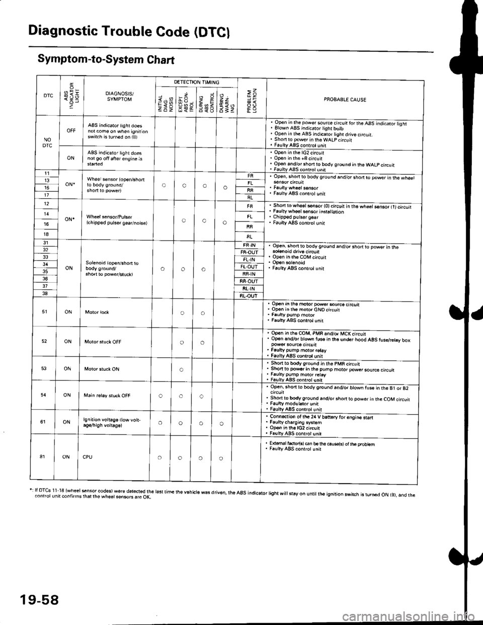
Diagnostic Trouble Code (DTCI
Symptom-to-System Chart
DTC
oH1=DIAGNOSIS/SYMPTOM
DETECTION TIMING
>=PNOBABLE CAUSEi.'sEV98€E
zr\9=6<_6
=t
6tz
NODTC
ABS indicator iighr doesnot com€ on when ignirionswrt.h is lu.ned on (ll)
, Open in the pow€. source circ!ir ror the ABS -.ndicato;l isht. Elown ABS indicalo.lighr butb' Open in rhe ABS indicaror tight drive cncuit.. Shori ro pow€r in theWALpcircuit. FaultyABS contrct!nit
ONABS indicator light doesnol90 oft 6frer engine isOpen in the lG2 circuitOpon in the +B circuirOp€n andlor short ro body ground jn the WALP circuitFaultv AAS coni.ol unnt1
oN.Wheel sensor (op€n/shortOooo13upen, snofiro bodyground and/or shodro power in rhe wh€61
Faulty ABS co.lrctunitllBL12
oN.(chipp€d pulser gea/noise)oao
Short to wh6sls€n6or (O)circuir in t'e.h;;Go-nso, trtcircutiFaulty whsel s€nsor insra|ation
Faulty ABS cont.olunir
I8
31
ONSolenoid (open/shon roaoa
Op.ni shon to bodyground and/o. shorrto powsr in rhe
op€n in lh6 coM circuit
Faulty ABS conlrclunit
32F8-OUTFL.IN3'lFT.OUTRF.IN88 OUT318t rN38RLOUT
ONoo
op€n in tho motor pow€..ourco circliaOp€n inih€ moro.cNOcircuit
Faulty ABS conrrol unit
52ONoo
Open in rh€ COM, PMR 6nd/o. MCKcircuirOp€n.n.Vor blown lus€ in the under hood AgS rusdretry box
Faufty pump moto. rotayfaulv ABS conlrolunit
53ONo
. Sho.tto bodygrou.d in the pMR circuit. Shon to powsr in tha puhp moror pow6rsource circu. r.urty pump motor.etay, FalltyABS contolunit
54ONooc
Open, rhorr ro bodygrcund and/or blown fus€ in the B1 or 82
Shonto body ground.n.Vor short to powor in rhe COM circuitFaulty modul.tor unnFaulty ABS controt unit
ONlgnition voltage (low vott-oooo
. Connection ot the24 V bariorv tor enqins starr. Faurtycharoins system. Op€n in th6lG2 circuit. Fa!lly ABS contrcl unil
81ONCPUoooo
E {€rml facior{sl en bs rhe ouse{sl ot |he probtemF.ulty ABS conrrot unit
r: It DTcs 1 1 18 {wheel sensor codes) wore del*ted the lasr time the v6h cls wEs d riv€n, rhe a8s indicator tight wi
stay on u ntit lh6 ignition swirch is rurn6d oN t), and theconnorunit contnms rhat rhe wheet sensoB . rc OK,
19-58