Page 1961 of 2189
- How the Circuit Works
Radiator Fan
Voltage is provided at all times to the radiator fan
relay (contacts) through fuse 57. With the ignition
swilch in ON (ll), voltage is provided to the coil of
the relay through luse 17.
The radiator tan relay can be grounded through
either the engine coolant temperature switch or the
engine control module (ECM) or powertrain control
module (PCM).
The engine coolant temperature switch grounds
the radiator fan relay (coil) when the engine
coolant temperature exceeds 199'F (83'C). The
switch opens when coolanl temperature
decreases 3'- 8'C.
Condenser Fan
Voltage is provided at all times to the condenser fan
relay (contacts) through fuse 56. With the ignition
switch in ON (ll), voltage is provided to the coil of
the relay through fuse 17. When you push the A'lC
switch and put the heater fan switch in 1, 2,3, o( 4
position, the ly'C thermostat comes on, the
condenser fan relay energizes, and the condenser
fan motor runs.
A,/C Thermostat
The A,/C thermostat is located on the evaporator
housing. The A,/C thermostat tums off the A/C
compressor clutch if the temperature at the
evaporator goes below 3'C (37'F). This prevents
condensation from freezing on the evaporator fins
and blocking the air delivery into the passenger
compartment. lf the temperature goes below 3'C
(37"F) tuming off the Ay'C thermostat, ground will be
removed from the condenser fan relay. This will
deenergize the relay and remove voltage from the
condenser fan motor causing the fan to stop running.
Reter to the Service Manual (Section 23, Eleckical)
for specific tests or troubleshooting procedures.
63-3
Page 1965 of 2189
Integrated Control Unit
NOTE: Fuse 31 is hot with lgnition Switch in START (lll) and clutch pedal depressed or A,/T Gear Selector in
PARK (P) or NEUTRAL (N), see Starting System, page 21,21-1, ot 21-2.
See BrakeSystemlndicatorli^hl
FUSE 3IstaaTEaSIGI{AT7AAI
I
I
I
I
I
\
\
\
\
\
\
I
I
I
I
I
I
/
S€s SiarlingSyslsm, pago 21,21-1. or 21'2.
SEs BrakeSystemlndicetorLight A6
SsaClharSrrESystom
Eog GoundDistlbution,page l,l-7.
L------3c420PHO|O 63vtEw 53
--r-r..r'
FED/BLU
SeeCeilingLightSee Seat Beltand lgnitionKey Remind€rs
t@
i'l-;;,-lH8B'r*| rrmn1gn I FUSEI
i f t*" ig8f"LJr____J PHOTO 7
u'lf tf,%,
S vtEw 3a
wHr/FED
| 3fl3,n'"n
wHr,FED I sYsteh
<--=- !t
,r"r,".0 | ,n"r,".u I
| .l B*?r:"" ,.!,.*,
Page 1967 of 2189
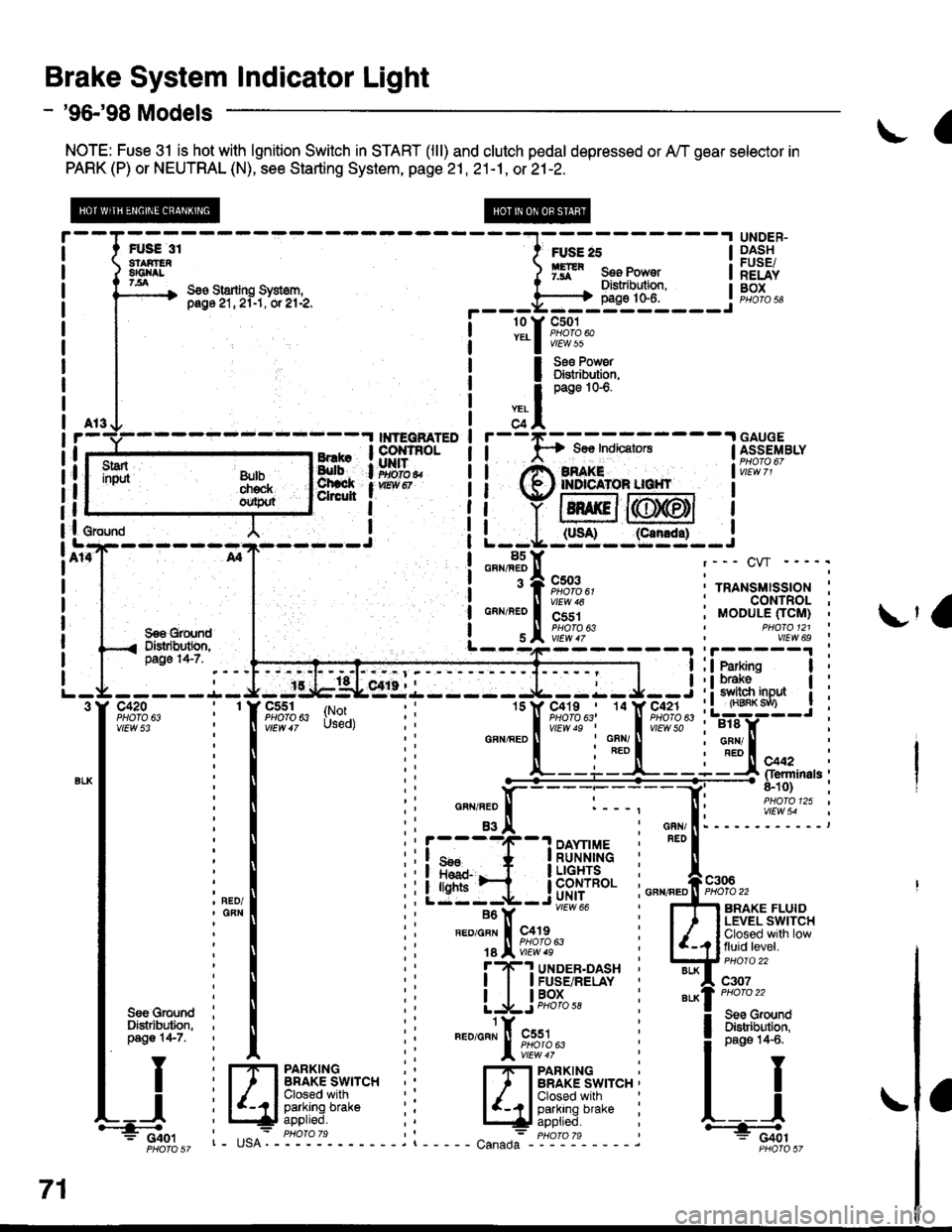
Brake System Indicator Light
- '96-'98 Models
NOTE: Fuse 31 is hot with lgnition Switch in START (lll) and clutch pedal depressed or A,/T gear selector in
PARK (P) or NEUTRAL (N), see Starting System, page 21 , 21-1, or 21-2.
a
FUS€ 31atAirEn8Gl{tt7.all
UNDER-DASHFUSE/RELAYBOXS€o Starling Sysl6m,pag6 21, 2l-1, or el-2,
FUSE 25
ffR s." Ponr"tDistribulion,page 10-6.
rry
I
;?l
r
I
I
I
I
I
I
I
c501PHOTO 60vtEw 55
Ss€ Pow6rDlstribution,page 1G6.
---.I GAUGE$os IndicatorsI ASSEMBLY
i',i!i,I2'
I
I
(slt--95.:l-_i
l8s: GRN/FEDr--- CW ----.
! 3 A cso3 :..^.,"..,"",^.;i "lir%?u' ' rRANsMls-sloN :! ll virw ro : CONTROL ;
99€ grqn'd | ! s I iiiiir^ , vtLw 6s
i o"^r"'o |
'i'jri
| "lw;t,b---4---- 31i3*:'. --l:ffiffi--i
i
---- -.L- J- -:g,tgLesr.l - ---- J--:- J--i : ! 3113'"0* | :-9tF":--T-tY-E;"41i'",
: : lsrss9l;-;?--q1Al" :L:W-J i
-----.1- J- -tlb$Lsr'{.i------ J--:- J--i : ! 31ffi "o* | i-trfr; - -
i
-TFr,lifu:i-|l - - .Tf"*;',r;,f'.F?f;l', i LTS-: :
i I ii
-""'"L--i:t--i3trFlr*n'"i
i mooule ficlrt) iI PHO|O 121 '
:! :i ffitre"ninas;: ll ti n"",".0 ll :---. [: i,119i9."' ''tl
: I :i asi: '.I i eri: -----':::---:
i",",1 iiiffi_il$.t'ii: i"-,s*
vlEw 54
-- vtEot 66 , Ffl anlxe rLUto
i*l
' ".","1;l,"p;a;
illJff*ttt**
u.-u.*il ii [JFHi:"'l*iTfit*,".
I Y i frpanxrxc :' r#"Al[';u3*'""i
I I
U il4.lFfffff'UJ:"" ii EJi,fii,i,"-" i r-j
3"ilj*il
ii
"."""J[ft*,,tl-
i lilt:','x;l
71
i Cior I tE^- phoroTs ,l - : pHoro 7s * C+6tF6r6sz r- usA. - - - - - . t - - - - - canada Froiit sz
Page 1968 of 2189
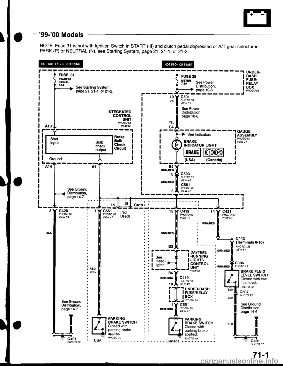
- '99-'00 Models
NOTE: Fuse 31 isJtot with lgnition Switch in START (lll) and clutch pedal depressed or A,,/T gear selector inPARK (P) or NEUTRAL (N), see Starting System, page 21 ,2i-1, ot 21-2.
UNDER"DASHFUSEiRELAYBOX
I
I
I
I
I erouna
BrakeBulbChsckCheuh
NTEGNATEDcot{TRoLUNITftoa 64vEw a7
I Bi?[lT':i,
S€6 GroundDistribution,pago 14-7.I
I
c420PHO|O 6ivtEw 53
c551PHOfA 63c419PHO|O 63 |(r;'Used)
1514
r----4(--.1 DAYnMEI q* * |RUNN|NG
Llt:i-ib'f#Iu'"'' i---Y -- """* i
FED/GFN I c419 :
18 Jl iE?'8' :f ?-'! uloen-oasx 'I I I FUSE/RELAY
| | lP9l_- :
1 Y Cs51".o'o"" ! iffl1oru"
l:
I Sss GfoundI Distribution.I pag€ 147.
TY
tt
L_l.'-4o.'
Fr,lrs 3i
--Iil;--------l
3m" ) 9ff" s"" po*"r I
\, See Starting system. I "- . Distribution. l- pasezr.zi-t.'or'ztlz. ._____=Fl}_*t0"_____.1
l3.f ftT:4""
Bulbchekoutp$
L----------
,.. I
o"n" tot'
c+l
i
- -
F-; ffi ;-
- - -
I [i;"s"'"."I rt^ amre I vir:i i,
t (R ' rNprcAroR uGHr I
i Y lBn rcll6T6tl I
| | (usA! (canrda) |L--*-:J- -:--'�-- J85Y85Yo""'"T|
"";%u,
"""'"';i"a#;",
\e#1k"
I
f,............ c44,
f $?'#"ot'to'-*'1;;
GBN/FED II PHOIO 22
5fi ennxe rluroI ' I LEVEL SWITCH
| /_,? lfJ",ii"."gl'.-
w::::"
"'-1":::::-.
! 3:"'lll"*l
".-l I
L__l+: G40lPHOIO 57
l-rlrl PARKTNGI ' I BRAKE SWITCH ,
lIdft"f[]r'"r'" i
c"n"o":- "igt-ol'- - - - - j
71-1
Page 1969 of 2189
Brake System Indicator Light (cont'd)
- How the Circuit Works
The brake system indicator light comes on to alert
the driver that the parking brake is applied, or that
the brake fluid level is low. lt also comes on as a
bulb test when the engine is cranked.
Parking Brake
With the ignition switch in ON (ll) or START (lll),
voltage is applied through fuse 25 to the brake
system light. When you apply the parking brake, the
switch closes and provides a ground for the light.
The light then comes on to remind you that the
parking brake is applied.
Brake Fluid Level
With the ignition switch in ON (ll) or START (lll),
voltage is applied through fuse 25 to the brake
system light. lf the brake fluid level is low, the brake
fluid level switch closes, providing ground to the
circuit. The brake system light then comes on,
alerting the d verto a low brake fluid level in the
brake master cylinder. (Check brake pad wear
before you add fluid).
Bulb Check
With the ignition switch in START (lll) and clutch
pedal depressed or A'lT gear selector in PARK (P)
or NEUTRAL (N), voltage is applied through fuse 31
to the brake bulb check circuit. The brake bulb
check circuit closes, allowing current to flow through
the brake system light and bulb check circuit to
ground. The brake system light then comes on to
test the bulb.
Refer to the Service Manual (Section 23, Electrical)
for specific tests or troubleshooting procedures.
71-2
a
\fa
Page 2045 of 2189
\.
!l f-+ iffi,iiilili. lsivvncrr I
ii^ / _;l"d:lt':"i i:ll*cK ( - t*.r.$r Ii!tff^.I^-.-f fl''i" I r
i! ti't|l ! rL---------J-{,5=;==---)"'*TA
"o'uetxret I Pflllodo
l:'iISECURITYSTARTERCUT RELAYPHOTO 53PTOIO 56 ( 98 modsls)vlEW 12
STEERINGLOCK
a
lll except CW
!'G";1cutouiput
SECURIryCONTROLUNIT
vtEw 58
MrrCVT
;BLKTTVHT
('98 model 5)
"a*-", Io
.I A/T GEARI POSTflONa swtTcHPHOfO 78STARTERCUTRELAYfrc433Bt( vHT
10aL|( vHr('98 model 3)4
BLU/BLK
--T6-';'d"r tlf3l
".,u".o I
T
I
cLUrcH llTNTERLoCK I
Slig:i* J,clutchpedalfullyoepresseo.
8LK/FED11t A/T GEARI POSTTTONa swrTcH
I
I
IJ
c433ot-r\
L!
BLKRED
".o"ro! BLvFEo.@
"'o"'r"f,
"'ot
ro'ffzr----,
SeeStartingSystemSe€ G.oundDistribution,page l4$.
BLKAVHTTY
II
L____l+.: G401PHOTO 57
STARTER
r::1 STARIER
I uo'r I soLE orD
tl
;-
".orr.i tr-
- -
to :l cat t
*"1.;
[;z*e'
an
L---J---ALI(RED
",#"It#f;,.+,"
rl r
L--------J
133-3
Page 2049 of 2189
STEEBINGLOCK
SECURITYSIARTEFCUT RELAYPHO|O 56vtEw 12
MrtA/f sxcept CWcw
BLKAIIIfITIo
"'li'l
t**,"BLK,^,HI ll V/Ew 4 r
c433PHOIO 76
BLKr{VHT't0
BLK/IIT/HT
TXa.ta
t
II
,I
I
I
I
I
I
POSTTtONswrTcH
STARTERcurRELAYPHO|O 135
\*
l:l
I
------;r
I
",-o"ao IT
I
cLUrcH i
$fri*'fl:J Iclutch -
pedalfullyoepresseo.PHO|O 130
c433I
t-
BLK/FED
A/T GEARPOStTtONswtTcH*\"
LL
"."JJ"!F;?',?,-
".o"ro! BLKFEDo@SeeStarting
STARTER
Seo GfoundDistribution,page 14-6.)21I
c101
vtEw 2l2A
il
System
START
r::-1 STAHTER
I uo" lsoLENotD
tl
ii-=1;-i*r*iTfifil I
il.^-.. ./ _ r.n:'o ! r
!!r3"'.rhil.1ilr- i !--ii-;;;I'-----==----
**,^r..! i'i"i'
"-dI
iryissu'Y
\.
L--------J
34
133-7
Page 2054 of 2189
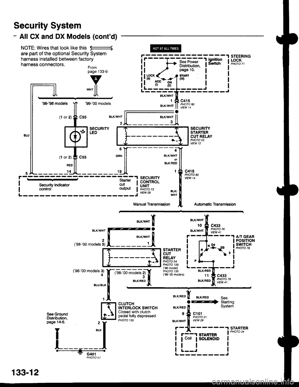
Security System
- All CX and DX Models (cont'd)
NOTE: Wires that look like this S--------S
are part ol the optional Security System
harness installed between lactory
harness connectors.Frompage j33_9.
@
aLI(AVHI
IAIKWHT
STEERINGLOCK
v
""'ll
'99198 models
(l or
1T
Jl.
'99100 models
sEcuRrwLEO
c415
vlEw 14
l-
SECURITYSTARTERCUT RELAYPHO|O 53vtEw 12
BLI(FEO't1
au(/FEo
c433
Aubrnatb Transmission
c4r 5PHOTO N
AU(WHT't0
BLXAVI{TBLKT'!VHT
2('98-'00 mod€ls 5)
('98100 models 3)4
A"IT GEARPOStTTONswtTcH
".**"rI
[ :,iSTARTERCUTRELAYPHO|O 54PHO|O 129( 9€ model)
( 9+ 00 models)
?
I
I
I
I
I
1-sel-oo rnJ"ls z1'[
".*"9tr
c433
CLUTCHINTERLOCK SWITCHClosed with clutchpedaltully depressed.
".o""0! ".o".0 seeaE4 Starting
ar-rvneo ll System
'f, "";%,,BLK TTBT I
vrEw28
r-11------.|STABTER
! r3r smnren I PHoro 34
| 1 coit ; SoLENOID I
i !.__J iL--------J
"===-F=F*F,Ff
Tfo?"
It -,/ Pase 10 l
!ltb3'-fi:-#-1iln i
ll .",;T; "":JI------;;lt
ll *"ll ll ELKBEDII
,JL----- 'dl*------ 'll t{
paso 14€. " y
I
*-l
L_______l.------+;_ -
PHO|OST
133-12