2000 HONDA CIVIC radio
[x] Cancel search: radioPage 1662 of 2189
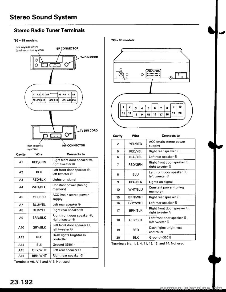
Stereo Sound System
Stereo Radio Tuner Terminals
'96 - 98 models:
For keyless entry . t6p coNNEcroR(and securrty) syslem
To DIN CORD
To DIN CORD
(for securitysystem)
Cavity Wire
A1RED/GRNRight front door speaker o,
right tweeter @
BLULeft front door speaker @,
left tweeter @
A3RE D/B LKLights-on signal
A4WHT/BLUConstant power (tuning
memoryl
A5YEL/REDACC (main stereo power
suppry)
A7BLUI/ELLeft rear speaker O
A8RE DI/E LRight rear speaker O
A9BRN/BLKRight front door speaker O,
right tweeter o
A10GRY/BLKLeft tront door speaker O,
left tweeter O
412REDDash lights brightness
controller
A14BLKGround (G501)
415GRYMHTLeft rear speaker O
Al6BR N/VVHTRight rear speaker O
Terminals A6, A11 and A13: Not used
23-192
'99 - 00 models:
CsvityConnccts toWire
2YEL/REDACC (main stereo power
suppry)
5RE DI/E LRight rear speaker @
BLUI/ELLeft rear speaker @
7RED/GRNRight front door speaker @,
right tweeter @
8BLULeft front door speaker @,
left tweeter @
9RED/BLKLights-on signal
10WHT/BLUConstant power (tuning
memory)
15BRN,ryVHTRight rear speaker O
GRYMHTLeft rear speaker O
17BRN/BLKRight front door speaker O,
right tweeter O
18G RY/BLKLeft front door speaker O,
left tweeter O
'19REDDash lights brightness
controller
20BLKurouno t(l5u t,
Terminals No. 1, 3, 4, 11,12, 13, and 14: Not used
Page 1669 of 2189
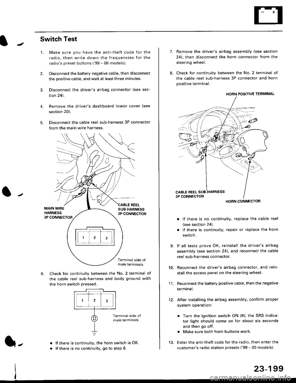
Switch Test
lMake sure you have the anti-theft code for the
radio, then write down the frequencies for the
radio's preset buttons ('99 - 00 models).
Disconnect the battery negative cable, then disconnect
the positive cable, and wait at least three minutes.
Disconnect the driver's airbag connector (see sec-
tion 24).
Remove the driver's dashboard lower cover (see
section 20).
Disconnect the cable reel sub-harness 3P connector
from the main wire harness.
2.
3.
4.
5.
1.
MAIN WIREHARNESS3P CONNECTOR
SUB-HABNESS3P CONNECTOR
REEL
6.
Terminalside olmale terminals
Check for continuity between the No. 2 terminal of
the cable reel sub-harness and body ground with
the horn switch pressed.
alf there is continuity, the horn switch is OK.
lf there is no continuity, go to step 6l-
-\
1.
8.
10.
'I 1.
9.
Remove the driver's airbag assembly (see section
24), then disconnect the horn connector from the
steering wheel.
Check for continuity between the No. 2 terminal of
the cable reel sub-harness 3P connector and horn
positive terminal.
lf there is no continuity, replace the cable reel
(see section 24).
lf there is continuity, repair or replace the horn
swtlcn,
lf all tests prove OK, reinstall the driver's airbag
assembly (see section 24), and reconnect the cable
reel sub-harness connector.
Reconnect the driver's airbag connector, and rein-
stall the access panel on the steering wheel.
Reconnect the battery positive cable, then the negative
termtnar.
After installing the airbag assembly, confirm proper
system operation:
12.
Turn the ignition switch ON (ll); the SRS indica-
tor light should come on for about six seconds
and then go off.
Make sure both horn buttons work.
13. Enter the anti-theft code for the radio, then enter the
customer's radio station presets ('99 - 00 models).
HORN CONNECTOR
23-199
Page 1714 of 2189
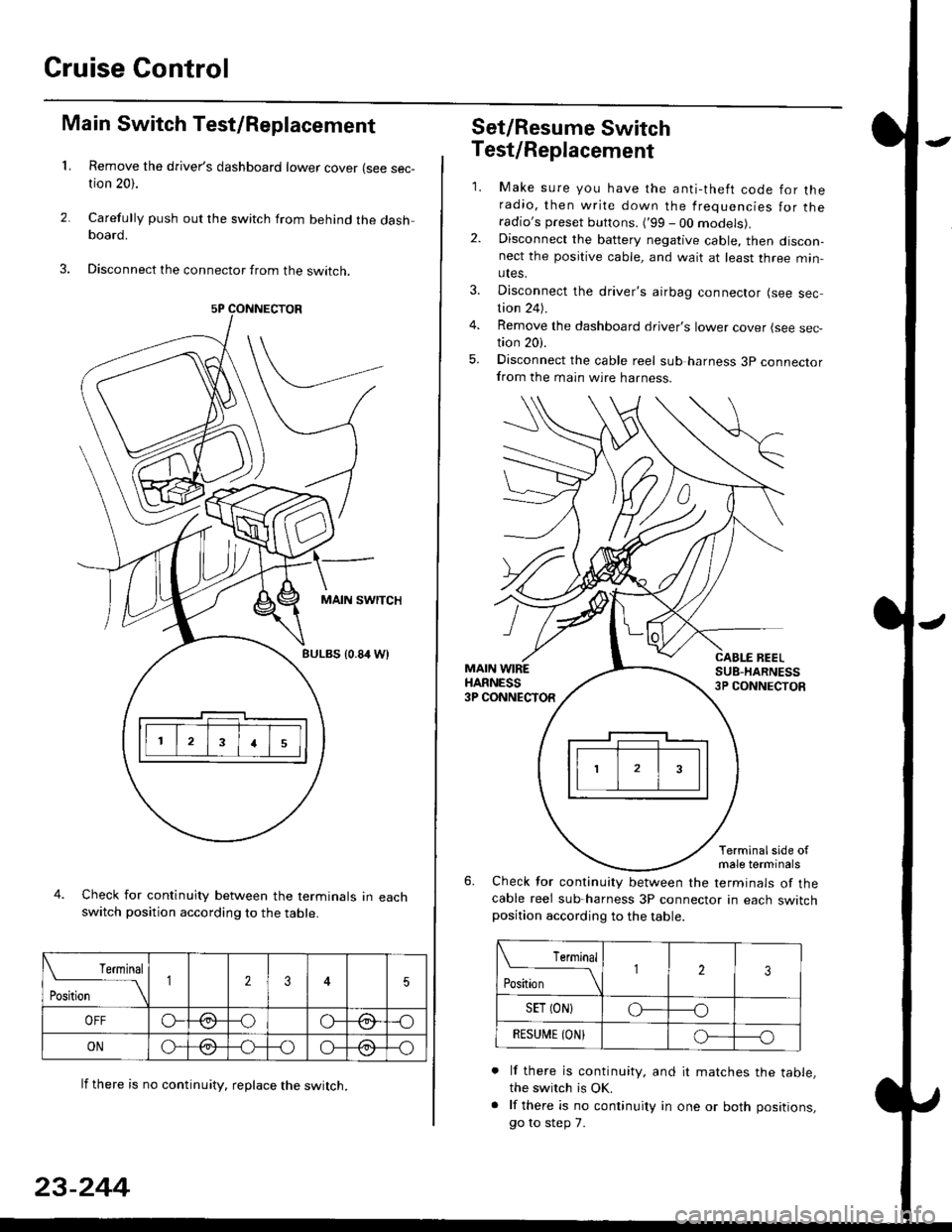
Cruise Gontrol
3.
1.
2.
Main Switch Test/Replacement
Remove the driver's dashboard lower cover (see sec-tion 20).
Carefully push out the switch from behind the dashboard.
Disconnect the connector from the swtrcn.
MAIN SWITCH
BULBS {0.84 Wt
Check for continuity between the terminals in eachswitch position according to the table.
lf there is no continuity. reDlace the switch.
4.
Terminal
r**
--\235
OFFo--oGa\-o\:./\a/
ONo-/a-oo--o\:/\:/
23-244
Set/Resume Switch
5.
Test/Replacement
2.
1.
MAIN WIREHARNESS3P CONNECTOR
Make sure you have the anti-theft code for theradio, then write down the frequencies for theradio's preset buttons. ('99 - 00 models).Disconnect the battery negative cable, then discon-nect the positive cable, and wait at least three min-utes.
Disconnect the driver's airbag connector (see sec-tion 24).
Remove the dashboard driver's lower cover (see sec,tion 20).
Disconnect the cable reel sub harness 3p connectorfrom the main wire harness.
CABLE BEELSUB-HARNESS3P CONNECTOS
Terminalside ofmale terminals
Check for continuity between the terminals of thecable reel sub-harness 3P connector in each switchposition according to the table.
L Terminal
Position123
SET (ON}o----o
BESUi,|E IONIo-----o
lf there is continuity, and it matches the table,the switch is OK.
lf there is no continuity in one or both positions,
go to step 7.
Page 1715 of 2189
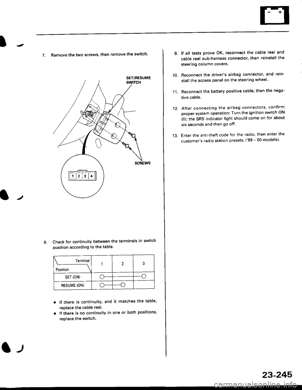
7. Remove th€ two screws, then remove the switch'
Check for continuity between the terminals in switch
position according to the table.
Terminal
t"-"t*
-\23
SET (ON)o--o
RESUI\4E {ON}o----o
lf there is continuity, and it matches the table,
replace the cable reel.
lf there is no continuity in one or both positions,
reDlace the switch.
8.
SET/NESUME
l-l
23-245
11.
q
10.
12.
lf all tests prove OK, reconnect the cable reel and
cable reel sub-harness connector, then reinstall the
steering column covers
Reconnect the driver's airbag connector. and rein-
stall the access panel on the steering wheel.
Reconnect the battery positive cable, then the nega-
tive cable.
After connecting the airbag connectors, confirm
proper system operation; Turn the ignition switch ON
(ll); the SRS indicator light should come on for about
six seconds and then go off.
Enter the anti-theft code for the radio, then enter the
customer's radio station presels {'99 -00 models)'
Page 1721 of 2189
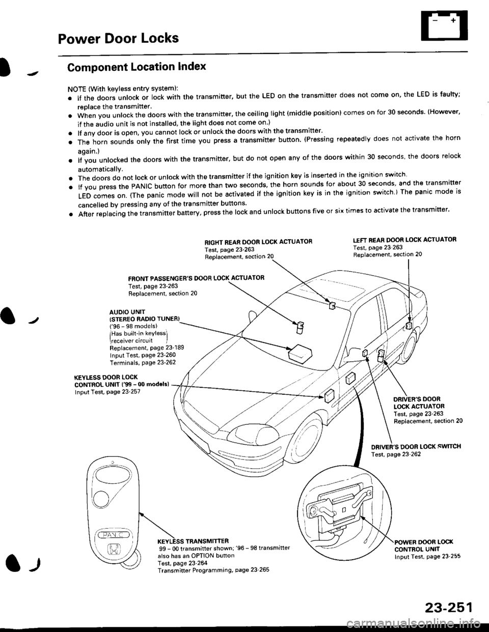
Power Door Locks
Component Location Index
NOTE (With keyless entry systeml:
. It the doors unlock or lock with the transmitter, but the LED on the transmitter does not come on, the LED is faulty;
replace the transmitter'
. when vou unlock the doors with the transmitter, the ceiling light (middle position) comes on for 30 seconds. (However,
if the audio unit is not installed, the light does not come on )
. lf any door is open, you cannot lock or unlockthe doors with the transmitter'
. The horn sounds only the first time you press a transmitter button. (Pressing repeatedly does not activate the horn
again.)
o lf vou unlocked the doors with the transmitter, but do not open any of the doors within 30 seconds, the doors relock
automatically.
. The doors do not lock or unlock with the transmitter if the ignition key is inserted in the ignition switch
. lf you press the PANIC button for more than two seconds, the horn sounds for about 30 seconds, and the transm'fer
LED comes on. (The panic mode will not be activated iJ the ignition key is in the ignition switch ) The panic mode is
cancelled by pressing any of the transmitter buttons'
o After replacing the transmitter battery, press the lock and unlock buttons five or six times to activate the transmitter'
Replacement, section 20
FRONT PASSENGER'S DOOR LOCK ACTUATOR
RIGHT REAR DOOR LOCK ACTUATOR
Test, page 23-263
I.IFT REAR DOOR LOCK ACTUATOR
Test, page 23 263Replacement, section 20
LOCK ACTUATORTest, page 23-263Replacement, section 20
ORIVER'S DOOR LOCK SWITCH
Test, page 23'262
DOOR L@XCONTROL UN]TInput Test, page 23 255
23-251
Test, page 23-263Replacement, section 20
AUDIO UNIT(STER€O RADIO TUNER)
{'96 - 98 models)
lHas built-in keylessl
eceiver circuit IReplacement, page 23-189
Input Test, page 23-260
Terminals, page 23-262
KEYLESS DOOR LOCKCONTROL UNIT l'99 - 00 modelsl
Input Test, Page 23-257
l-l
TRANSMITTER99 - 0O transmitter shown;'96 -98 transmifter
also has an OPTION buttonTest, page 23-264Transmitter Programming, page 23_265
Qi,,a/
/----
L(ru
i'.-8,-'l
/'-'6
Page 1827 of 2189
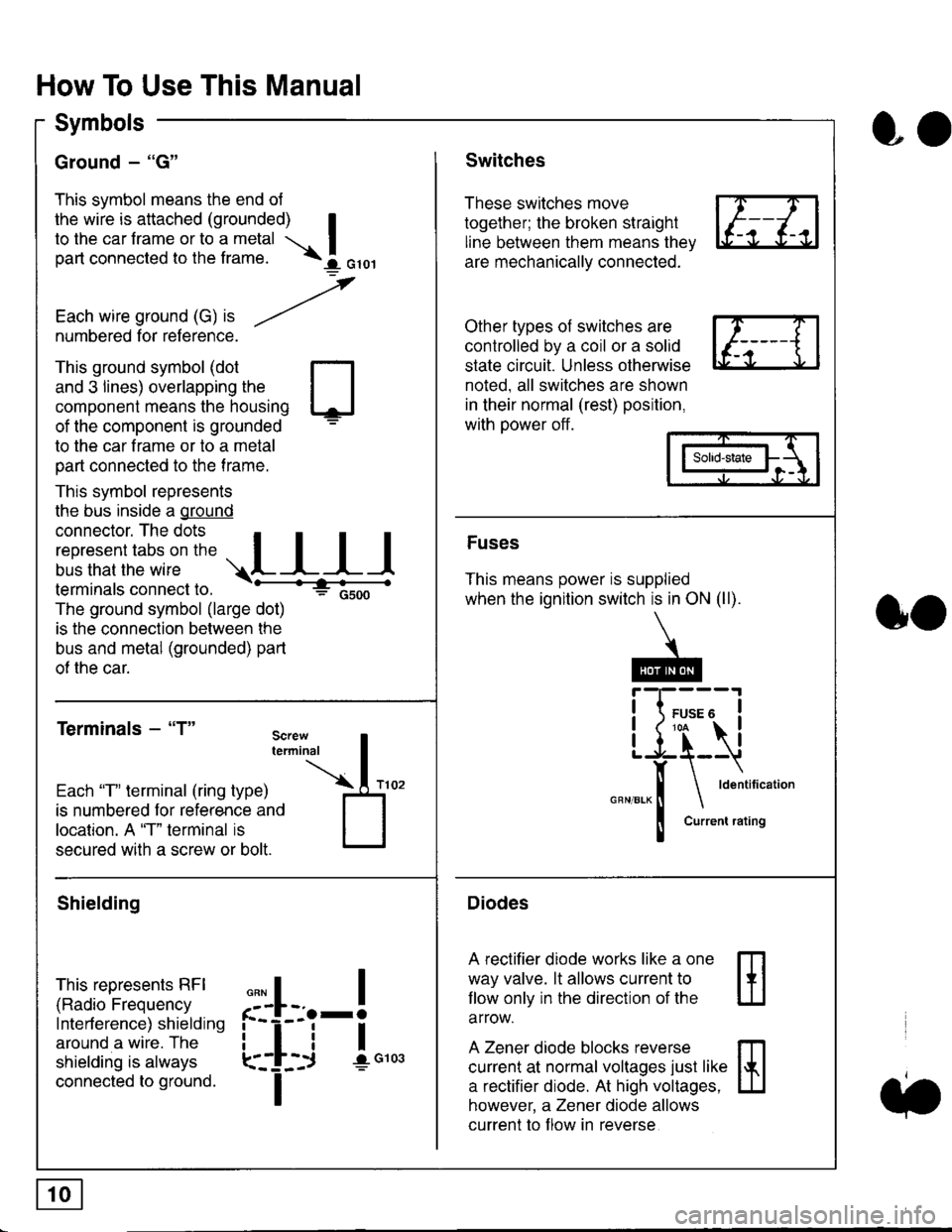
How To Use This Manual
Symbols
Ground - "G"
This symbol means the end ol
the wire is attached (grounded) Ito the car frame or to a metal I
part connected to the frame. \i oro,|
-t'
Each wire ground (G) it --/
numbered for reference.
oo
Switches
These switches move
together; the broken straight
line between them means the,
are mechanically connected.
Other types of switches are
controlled by a coil or a solid
state circuit. Unless otherwise
noted. all switches are shown
in their normal (rest) position,
with power off.
This ground symbol (dot
and 3 lines) overlapping the
component means the housing
of the component is grounded
to the car frame or to a metal
part connected to the frame.
This symbol represents
the bus inside a ground
connector. The dots I
i:l*,':1,'^:*,:"
;"
r"L I I I
terminals connect to.
The ground symbol (large dot)
is the connection between the
bus and metal (grounded) part
of the car.
Terminals - "T"
ffi
ffi
Solid-state
Fuses
This means power is supplied
when the ignition switch is in ON (ll).
Current rating
Diodes
A rectifier diode works like a one
way valve. lt allows current to
llow only in the direction of the
arrow.
A Zener diode blocks reverse
current at normal voltages just like
a rectifier diode. At high voltages.
however, a Zener diode allows
current to f low in reverse
oo
Each "T" lerminal (ring type)
is numbered for reference and
location. A "T" terminal is
secured with a screw or bolt.
Shielding
This represents RFI
(Radio Frequency
Interference) shielding
around a wire. The
shielding is always
connected to ground.
f--l;j-i",..
I
,,,,
T
Page 1835 of 2189
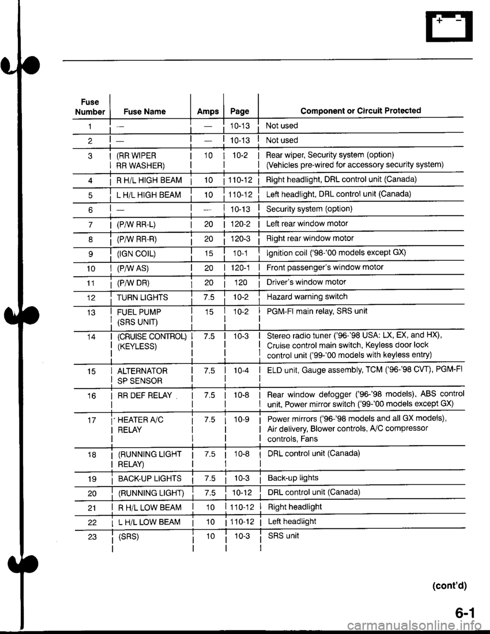
Fuse
NumberAmpsPageFuse Name
(RR WIPER
RR WASHER)
i R HiL HIGH BEAM | 10
L H/L HIGH BEAM
| (PAIV RR-L)
i (P/vv RR-R)
(rGN CO|L)
10I (P,^/V AS)
Component or Circuit Protected
Not used
Not used
Rear wiper, Security system (option)
(Vehicles pre-wired for accessory security system)
'10r 1n-2
I
| 1 10-12i Right headlight, DRL control unit (Canada)
Lett headlight, DRL control unit (Canada)
I ro-rsSecurity system (option)
| 120-2 | Left rear window motor
Right rear window motor
lgnition coil ('98-'00 models except GX)
| 120-1 | Front passenger's window motor
i (PiW DH)| 20 1 12O I Driver's window motor
TURN LIGHTSHazard warning switch
FUEL PUMP
(SRS UNIT)
PGM-FI main relav, SRS unit
(cRUrsE CoNTROL)
/KtrVt trSS\
Stereo radio tuner ('96-'98 USA: LX, EX, and HX),
Cruise control main switch, Keyless door lock
control unit ('99-'00 models with keyless entry)
15ALTERNATOR
SP SENSOR
l-a10-4I ELD unit, Gauge assembly, TCM (96-'98 CW, PGM-FI
16I RR DEF RELAY7.510-8I Rear window defogger ('96-'98 models), ABS control
I unit. Power mirror switch ('99-'00 models except GX)
i-HEATER r/C
I RELAY
Power mirrors ('96-98 models and all GX models),
Air delivery, Blower controls, AilC compressor
controls, Fans
I (RUNNING LIGHT
I RELAY)
1 7.5 1
tl
I DRL control unit (Canada)
i BACK-UP LTGHTSi Back-up lights
(RUNNING LIGHT)DRL control unit (Canada)
I R H/L LOW BEAM'10 l11o-12Right headlight
I L H/L LOW BEAM | 101110-12 | Left headlight
(cont'd)
(SRS)SRS unit
6-1
Page 1836 of 2189
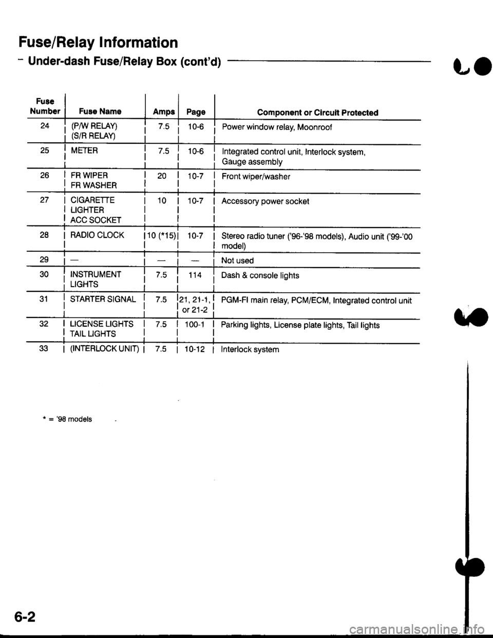
- Under-dash Fuse/Relay Box (cont'd)
Fuse/Relay I nformation
Fuse
NumberFuse NameAmps
(P/W RELAY)
(S/R RELAY)
FR WIPER
FR WASHER
LO
Page
10-7 |
I
Component or Clrcuit Protected
i Power window relay, Moonrool
Front wioer/washer
CIGARETTE
LIGHTER
ACC SOCKET
10-7Accessory power socket
I RAD|O CLOCK
I
110 115)l
tl
1O-7 |
I
Stereo radio tuner ('96198 models), Audio unit ('99100
model)
Not used
i 7.5i 114 iDash & console lights
I srnnrensrorunl | 7.slzl , zt -t , ! eCU-n main retay, PCM/ECM, Integrated controt unit
I ot 21-2 t
I LICENSE LIGHTS I 7.5
I rerr uesls I
Parking lights, License plate lights, Tail lights| 1oo-1 |
tl
| (f NTERLOCK UNIT) | 7.5 | 10-12 I Interlock system
* = '98 models
6-2