2000 HONDA CIVIC capacity
[x] Cancel search: capacityPage 257 of 2189
lllustrated Index
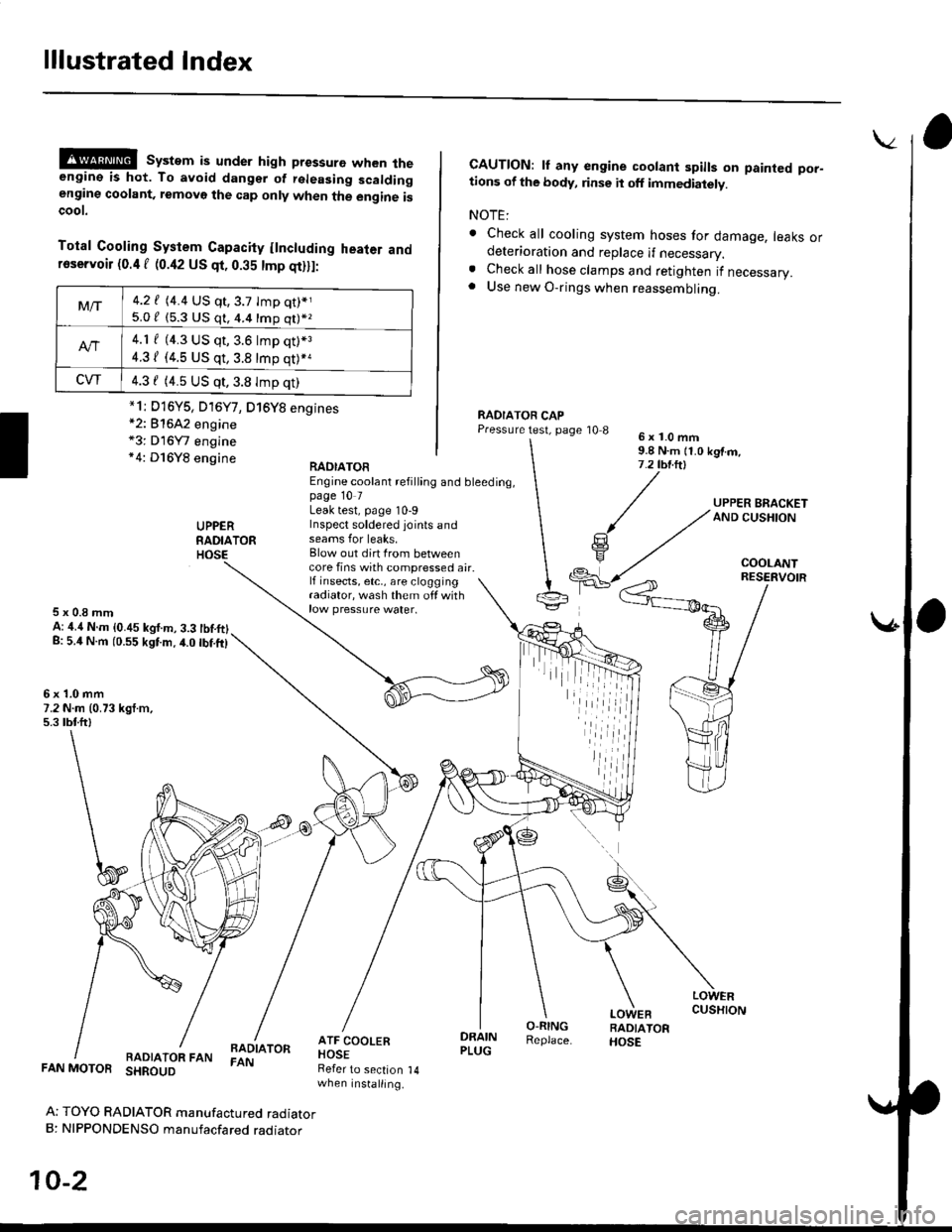
@@ system is under high pressure when theengine is hot. To avoid dangsr of rsleasing scaldingengine coolant, removo the cap only when the engine iscoot.
Total Cooling System Capacity flncluding heater andfoservoir (0.4 f (0.42 US qt, 0.35 tmp qt)ll:
*2: 81642 engine*3: D16Y7 engine*4: D16Y8 engine
CAUTION: lf any engine coolant spills on painted por-tions of the body, rinse it off immediately.
NOTE:
. Check all cooling system hoses for damage, leaks ordeterioration and replace if necessary.. Check all hose clamps and retighten if necessary.. Use new O-rings when reassembling.
RADIATOR CAPPressure test, page '10 86x1.0mm9.8 N.m {1.0 kgtm,7.2 tbt.ltl
UPPERRADIATORHOSE
UPPER BRACKETAND CUSHION
COOLANT
RAOIATOREngine coolant refilling and bleeding,page 10 7Leak test, page 10-9Inspect soldered joints andseams for leaks,Blow out dirt Irom betweencore fins with compressed air.lf insects, etc,, are cloggingradiator, wash them off withrow pressure water.
RESERVOIR
5x0.8mmA: ,1.4 N.m {0.45 kgf.m, 3.3 tbtftlg: 5.4 N.m (0.55 kgtm.4.0 tbf.ft)
6x1.0mm7.2 N.m (0.73 kgt.m,5.3 tbtftl
LOWERCUSHION
RADIATOR FANBADIATORFAN
DRAINPLUG
O-RINGReplace.
LOWEBRADIATORHOSE
FAN MOTOR SHROUD
Ar TOYO RADIATOR manufactured radiatorB: NIPPONDENSO manufacfared raoraror
10-2
Refer to section 14when installing.
Mt-|-4.2 f (4.4 US qt,3.7 tmp qt)*j
5.0 / (5.3 U$ q1, 4.4 16p q11*z
4.1 f (4.3 US qt, 3.6 lmp q0*3
4.31 (4.5 US qt, 3.8 tmp qt)*a
CVT4.3 f (4.5 US qt,3.8 Imp qt)
*1i D16Y5, D16Y7, D16Y8 engines
iil
Page 263 of 2189
Radiator
Engine Coolant Refilting and Bleeding (cont,dl
8. Mix the recommended antifreeze with an eoualamount of water in a clean container.
NOTE:
o Use only genuine Honda antifreeze/coolant.. For best corrosion protection. the coolant con_centration must be maintained year_round at50% minimum. Coolant concentrations less than50% may not provide sufficient protectionagainst corrosion or freezing.. Coolant concentrations greater than 60010 willimpair cooling efficiency and are not recom_mended.
CAUTION:
. Do not mix difforont brands ofar ilreeze/coolants.. Do not use additional rust inhibiiors or anti_rustproduqt3; they may not be compatible with thecoolant.
Engine Coolent Refi
Capacity Iincluding reservoir{0.4 f 10.42 US qr, 0.35 lmp qt),I;
*1: D16Y5, D16Y/, O16Y8 engines*2: 81642 engine*3; Dl6Y7 engine*4: Dl6Y8 engine
M/r3.8 f {4.0 US qt, 3.3 lmp qt)*1
4.5 / (4.8 US qt. 4.0 tmp qt)*,
Att3.7, (3.9 US qr,3.3 tmp qt).3
3.9 / (4.1 US qt,3.4lmp qt)*.
CW3.9 / (4.1 US qt,3.4 tmp qtl
10-8
\.-I
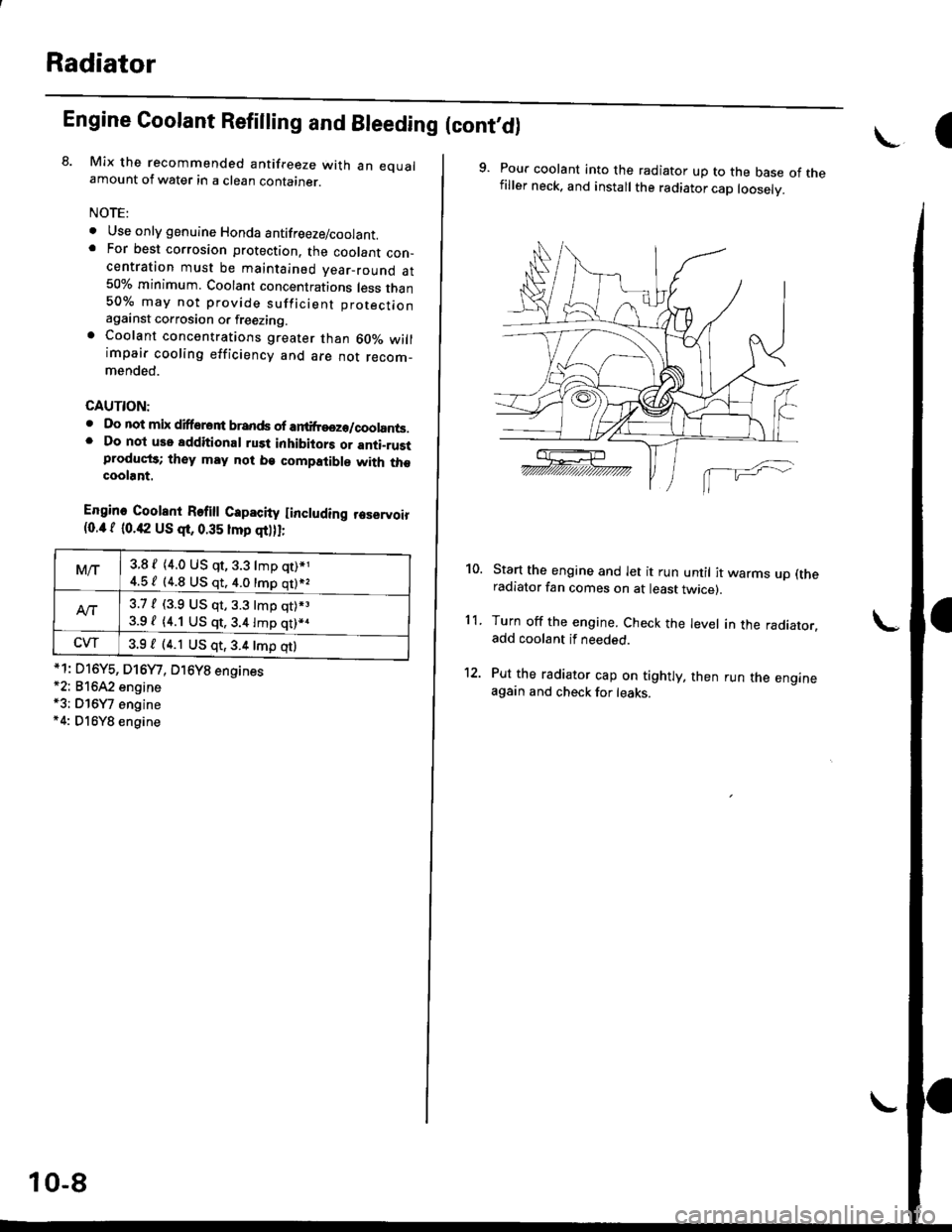
9. Pour coolant into the radiator up to the base of thefiller neck. and install the radiator cap looselv.
Start the engine and let it run until it warms up (theradiator fan comes on at least twicer.
Turn off the engine. Check the level in the radiator.add coolant if needed.
Put the radiator cap on tightly, then run the engineagain and check for leaks.
10.
11.
Page 522 of 2189

\
lTo420l Th" """n toot indicates Diagnostic Troubte code (DTc) p0420: catatyst sysrem efficiency below threshold.
Description
This system evaluates the catalyst's capacity by means of the Ho2s {Primary and secondary) output during stable driving
conditions. ll deterioration has been detected during two consecutive driving cycles. the MIL comes on and DTC P0420 will
be stored.
NOTE: lf some of the DTCS tisted below are stored at the same time as DTC P0420, troubleshoot those DTCS first. then
recheck for DTC P0420
P0137, P0138: Secondary HO2S (Sensor 2)
Po14'1:Secondary H02S {Sensor 2) Heater
Possibl€ Cause
. TWC Deterioration
. Exhaust system leakage
Troubleshooting Flowchart
I
The MIL has been reported on.
DTC P0420 is stored
Problem verilication:1. Do the ECM/PCM Reset Proce
dure.2. Start the engine Hold the
engine at 3,000 rpm wath no
load {in Park or neutral) until
the radiator fan comes on.
3. Connect the SCS service con
4. Test drive 40 - 55 mph for
approx, two minutes Then
decelerate for at least 3 sec_
onds with the throttle com'pletely closed- Then reduce
the vehicle speed to 35 mph,
and try to hold it until the
readiness code comes on
Intermittent Iailure, system is OK
at this time.ls DTC P0420 indicated?
Check the TWC {see section 9l
lf necessary, replace the TwC
Page 583 of 2189
MaintenanceBack-up Light Switch
Transmission Oil
NOTE: Check the transmission oil with the engine OFF
and the vehicle on level ground.
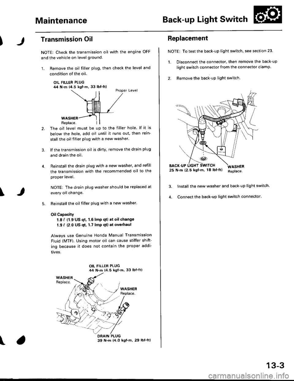
1. Remove the oil filler plug, then check the level and
condition of the oil.
OIL FILLER PLUG/14 N.m (4.5 kgl.m,33 lbl.ft)Proper Level
4.
WASHERReplace.
The oil level must be up to the filler hole. lf it is
below the hole, add oil until it runs out. then rein-
stall the oil filler plug with a new washer.
lf the transmission oil is dirty, remove the drain plug
and drain the oil.
Reinstall the drain plug with a new washer, and refill
the transmission with the recommended oil to the
proper lever.
NOTE: The drain plug washer should be replaced at
every oil change.
Reinstall the oil filler plug with a new washer.
OilCapacity
1.8 f (1.9 US qt. 1.6 lmp qtl at oil change
1.9 { (2.0 US $, 1.7 lmp qt) at overhaul
Always use Genuine Honda Manual Transmission
Fluid {MTF). Using motor oil can cause stiffer shift-
ing because it does not contain the proper addi-
t|ves.
\
\
Replacement
NOTE: To test the back-up light switch, see section 23
1. Disconnect the connector, then remove the back-up
light swirch connector from the connector clamp.
2. Remove the back-up light switch.
25 N.m (2.5 kgf'm, 18lbf'ltl
Install the new washer and back-up light switch
Connect the back-up light switch connector.
ASHER
13-3
Page 627 of 2189
MaintenanceBack-up Light Switch
\
Transmission Oil
NOTE: Check the oil with the engine OFF. and the vehi-
cle on level ground.
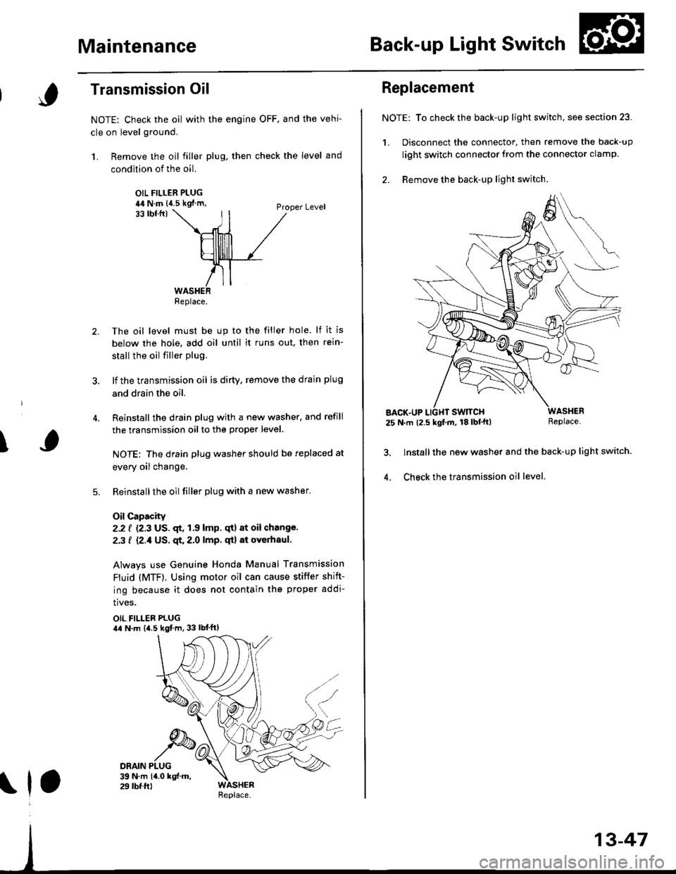
1. Remove the oil filler plug, then check the level and
condition of the oil.
OIL FILLER PLUGia4 N.m {{.5 kgf'm,Proper Level33 tbtfrl
The oil level must be up to the filler hole. lf it is
below the hole, add oil until it runs out, then rein-
stall the oil filler plug.
lf the transmission oil is dirty, remove the drain plug
and drain the oil.
Reinstall the drain plug with a new washer. and refill
the transmission oil to the proper level.
NOTE: The drain plug washer should be replaced at
every oil change.
Reinstallthe oilfiller plug with a new washer.
Oil Capacity
2.2 f {2.3 US. qt, 1.9 lmp. qtl at oil change.
2.3 f {2./f US. qt. 2.0 lmp. qt} at overhaul.
Always use Genuine Honda Manual Transmission
Fluid (MTF). Using motor oil can cause stiffer shift-
ing because it does not contain the proper addi-
tives.
OIL FILLER PLUGila N.m {4.5 kgf.m, 33 lbt'ftl
Replace.
\1,
Replacement
NOTE: To check the back-up light switch, see section 23.
1. Disconnect the connector, then remove the back-up
light switch connector from the connector clamp.
2. Remove the back-up lighr switch.
AACK.UP25 N.m 12.5 kgf.m, 18 lbf'tt)Replace.
lnstall the new washer and the back-up light switch.
Check the transmission oil level.4.
Page 796 of 2189

Fluid Level
Changing
NOT€: Keep all foreign particles out of the transmis-sion.
'1.Bring the transmission up to operating temperature(the radiator fan comes on) by driving the vehicle.
Park the vehicle on the level ground, and turn theengine off.
Remove the drain plug. and drain the automatictransmission fluid (ATF).
NOTE: lf a cooler flusher is to be used, see page 14-187 and 14-188.
TRANSMISgION END OOVER
DNAIN PLUG18 x 1.5 mm49 N.m (5.0 kgtm, 36lbf.ftlSEALING WASHERReplace.
Reinstall the drain plug with a new sealing washer,then refill the transmission with the recommended
fluid into the filler hole to the upper mark on thedipstick. Always use Genuine Honda premium
Formula Automatic Transmission Fluid (ATF). Usinga non-Honda ATF can aftect shift quality.
Automatic Transmission Fluid Capacity:
2.7 | |'2.9 US ql,2.a lmp qtl at Ghlnging
5.9 f 16.2 US qt. 5.2 lmp qt) at overhaul
I
14-11A
Page 976 of 2189

Fluid Level
l.Checking/Changing
CAUTION: while chscking and changing, be sure not to
allow dust and other toreign particles to ent€l inlo the
transmission.
Checking
NOTE: Check the fluid level with the engine at normal
operating temperature (the radiator fan comes on).
'1. Park the vehicle on the level ground. Turn oft the
engrne.
2. Remove the dipstick (yellow loop) from the trans-
mission, and wipe lt with a clean cloth.
NOTE: Check the transmission fluid 50 to 90 sec-
onds after shutting off the engine.
3. Insert the diDstick into the transmission.
DIPSTICK (YELLOW LOOPI
Remove the dipstick and check the fluid level.
should be between the uDDer and lower mark.DIPSTICK
5. lf the level is below the lower mark, add fluid into
the filler hole to bring it to the upper mark. Use
Genuine Honda CW Fluid only.
6. Insert the dipstick into the transmission.
14-299
Changing
1. Bring the transmission up to normal operating tem-
perature (the radiator fan comes on) by driving the
vehicle. Park the vehicle on the level ground, and
turn off the engine.
2. Bemove the drain plug, and drain the CVT fluid.
NOTE| lf a cooler flusher is to be used, see page 14-
352 and 14-353.
Reinstall the drain plug with a new sealing washer,
then refill the transmission with Genuine Honda
CVT Fluid to the upper mark on the dipstick.
Automatic Transmission Fluid CaPacity:
3.9 i (4.r US qt. 3.4 lmp qt) 8t chlnging
6.4 I (6.8 US qt, 5.6 lmp qt) 8t ov€lhaul
Rscommended Automatic Transmission Fluid:
Genuine Honda CVT Fluid-
Use Genuine Honda CW fluid only. Using other flu-
ids can affect transmission operation and may
reduce transmission liJe.
Change Interval:
Normal Condition: 30, 000 miles 148,000 km)
Severe Condition: 30,000 miles (48,000 km), but it
you drive at high sPeeds in high
t90"F (32'C) and abovol temper-
atures, the ttansmission fluid
should be changed evsrY 15,000
miles 124,000 km).
{-]lr
ORAIN PLUG18 x 1.5 mma9 N.7n (5.0 kgl.m, 36 lb{'ftl
SEALING WASHERReplace.
Page 1089 of 2189
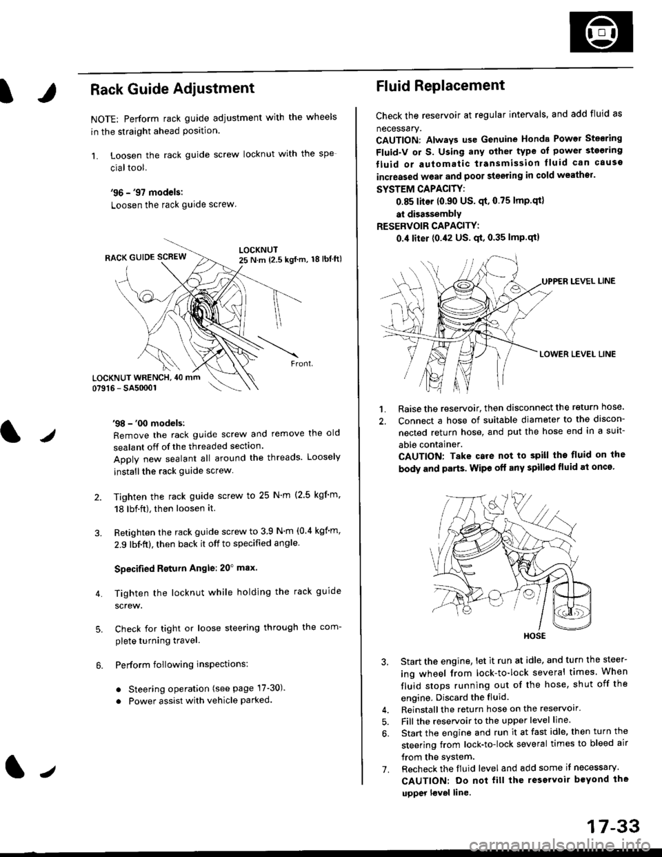
IRack Guide Adjustment
NOTE: Perform rack guide adjustment with the wheels
in the straight ahead Position.
1. Loosen the rack guide screw locknut with the
cialtool.
'96 - '97 models:
Loosen the rack guide screw
'98 - '00 models:
Remove the rack guide screw and remove the old
sealant off of the threaded section.
Apply new sealant all around the threads. Loosely
installthe rack guide screw
Tighten the rack guide screw to 25 N'm (2.5 kgf'm.
18 lbf.ft), then loosen it.
Retighten the rack guide screw to 3 9 N'm (0.4 kgim,
2.9 lbf.ft), then back it off to specified angle.
Specified Return Angle: 20" max.
Tighten the locknut while holding the rack guide
screw.
Check for tight or loose steering through the com-
plete turning travel.
Perform following insPections:
. Steering operation (see page 17-30).
. Power assist with vehicle parked.
4.
LOCKNUT WRENCH, 40 mm
lr
17-33
Fluid Replacement
Check the reservoir at regular intervals, and add fluid as
necessary.
CAUTION: Always us€ Genuine Honda Power Stearing
Fluid-V or S. Using any other type of power sto€ring
tluid or automatic transmission lluid can cause
increased wear and poor steering in cold weathor.
SYSTEM CAPACITY:
0.85 liter 10.90 US' qt,0.75 lmp'qt)
at disassembly
RESERVOIR CAPACITY:
0.4 liter (0.42 US. qt, 0.35 lmP.qt)
LEVEL LINE
LOWER LEVEL LINE
1. Raise the reservoir, then disconnect the return nose.
2. Connect a hose of suitable diameter to the discon-
nected return hose, and put the hose end in a suit-
able container.
CAUTION: Take care not to spill tho fluid on the
body and parts. Wipe off any spill€d fluid at oncs'
3. Start the engine, let it run at idle, and turn the steer-
ing wheel from lock-to-lock several times When
fluid stops running out of the hose, shut off the
engine, Discard the fluid.
4. Reinstall the return hose on the reservoir'
5. Fill the reservoir to the upper level line.
6. Start the engine and run it at fast idle, then turn the
steering trom lock-to-lock several times to bleed air
trom the system.
7. Recheck the fluid level and add some it necessary.
CAUTION: Do not fill the reservoir beYond the
upper l€vel line.
HOSE