Page 1988 of 2189
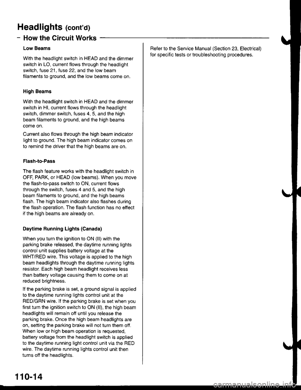
Headlight Switch
(
UNOER-OASHFUSEiRELAY BOXPHOTO 58
Sse PowerDisiribution,page 10-12-
UNDER-HOODFUSE/RELAYBOX
H
FUSE 22L H/ILOIY SEAflt0a
COMBINATIONLIGHTswtTcHHead-lightSwltch
L-----J'SeePower' Distribution,
: Page 10-12.
a
{
UNDER-DASHFUSE/RELAYBOXFUSS 2tF H/LLOW EgAtl
FUSE 4R TIILHIG|{ AEAMt0A
vtEw 53
_ ___:==
1-sr*r"
_
l_-.__
_,_.
it:
".0-", i ".o ".u I i ".o u.,
iti
Iti
llr
lli
lli
--'l --u{.sao,l,. i 2
neourrr I nroerul'/Ftr'o :---,
,.|,___ui
il--Tll''%i'sr"' ii
it@4li**"""li-; s-i5-r i .
I
I
i-t-;;l
1 J lff*n"' IL-.J----J
nrrl'?;Ii
ffif'illi! i
*itn12
HI
- - ) ot[*o1- -] ot. "roo a]ot.HEAD PAnK I panx IPAnK
!a
- -I DAYTIME
IRUNNINGI LIGHTS
! RESTSTOR'- Paqe 110-13
100
Page 2005 of 2189
- Canada\
-- f Pdoto\i3 A vttw.rsUNDER.DASHFUSE/RELAYBOX
DAYTIMERUNNINGLIGHTSCONTROLUNITvtEw 66
FUSE 2!(EUXMtIG7.5A
c420
vtEw 53
sE 20xM G Uclfr)
r'
I
I
IF
r
16
BIKWHT
See BrakeSystemIndicator Light
lcnvneo I
asl
-il*'*
IY
L_-J+: G401PHOTO 57
-
A4
B1
\BED/GRN
OAYTIMERUNNINGLIGHTSRESISTOR
S€e GroundDlstribution,page 1,1-6.PARKINGBRAKEswtTcHClosed withparking brakeapplied.H
Ughis-on Satterynpur
Hoadl8hi cornrol
lgnition
b'rak8 inputGround
Brake sysiemindicator lightcontrol
FUSE ra$r,rlxlxs ucl|l R€laY)7.ta
110-13
\
Page 2006 of 2189

Headlights (cont'd)
- How the Circuit Works
Low Beams
With the headlight switch in HEAD and the dimmer
switch in LO, current tlows through the headlight
switch. fuse 21 . fuse 22. and the low beam
tilaments to ground, and the low beams come on.
High Beams
With the headlight switch in HEAD and the dimmer
switch in Hl, current flows through the headlight
switch, dimmer switch, fuses 4, 5, and the high
beam filaments to ground, and the high beams
come on.
Current also llows through the high beam indicator
light to ground. The high beam indicator comes on
to remind the driver that the high beams are on.
Flash-to-Pass
The flash feature works with the headlight switch in
OFF, PARK, or HEAD (low beams). When you move
the flash-to-pass switch to ON, current flows
through the switch, fuses 4 and 5, and the high
beam filaments to ground, and the high beams
flash. The high beam indicator also flashes during
the flash operation. The flash function has no effect
if the high beams are already on
Daytime Running Lights (Canada)
When you turn the ignition to ON (ll) with the
parking brake released, the daytime running lights
control unit supplies battery voltage at the
WHT/RED wire. This voltage is applied to the high
beam headlights through the daytime running lights
resistor. Each high beam headlight receives less
than battery voltage causing them to come on at
reduced brightness.
lf the parking brake is set, a ground signal is applied
to the daytime running lights control unit at the
RED/GRN wire. lf the parking brake is set when you
first turn the ignition switch to ON (ll), the high beam
headlights will remain off until you release the
parking brake. Once the high beam headlights are
on, setting the parking brake will not turn them ofi.
When low or high beam operation is requested,
battery voltage from the headlight switch is applied
to the daytime running light control unit via the RED
wire. The daytime running lights control unit then
turns off the headlights.
Refer to the Service Manual (Section 23, Electrical)
for specific tests or lroubleshootrng procedures.
110-14
Page 2130 of 2189

65. Combination Wiper Switch
- Right side ot steering column
Connector A
- Natural- On main wire harness
1BLU (Windshield wipermotor LOW conkol)
BLU/YEL(Windshield wipermotor HIGH control)
YEUBLU (lntermittentwiper ON input)
lilale - GRNFemale - LT GRN(Rear window wipermotor conkol)
lrale - LT GRNFema|e _ LT GRN/BLK(Rear window wipermotor control)
4 GnN/BLK (Fuse 26)
5 BLK (G401)
7 BLU/BLK(lntermittenvpark wiper control)
8 WHT/BLK (Windshieldwasher motor)
BLK (G401)
Male - WHTFemale - GRN (Fuse 3)
Male - BLUF€male _ GRN/BLK(Rear window washermotor control)
\
Connector B (C4271 (with Rear Wiper)
- White- On main wire harness
3
5
6
)
I3
68
13
4
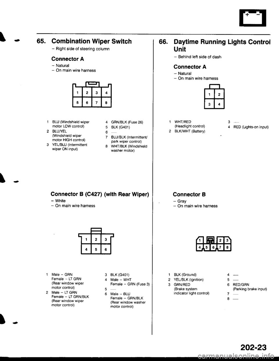
66. Daytime Running Lights Control
Unit
- Behind left side ol dash
Connector A
- Natural- On main wire
WHT/RED(H€adlight control)
BLKAVHT (Battery)RED (Lights-on input)
Connector B
- Gray- On main wire harness
narness
ffi
31
2
1
2
3
BLK (Ground)
YEUBLK (lgnition)
GRN/RED(Brake systemindicator light conkol)
RED/GRN(Parking brake input)
4
5
6
7
8
202-23
Page 2159 of 2189

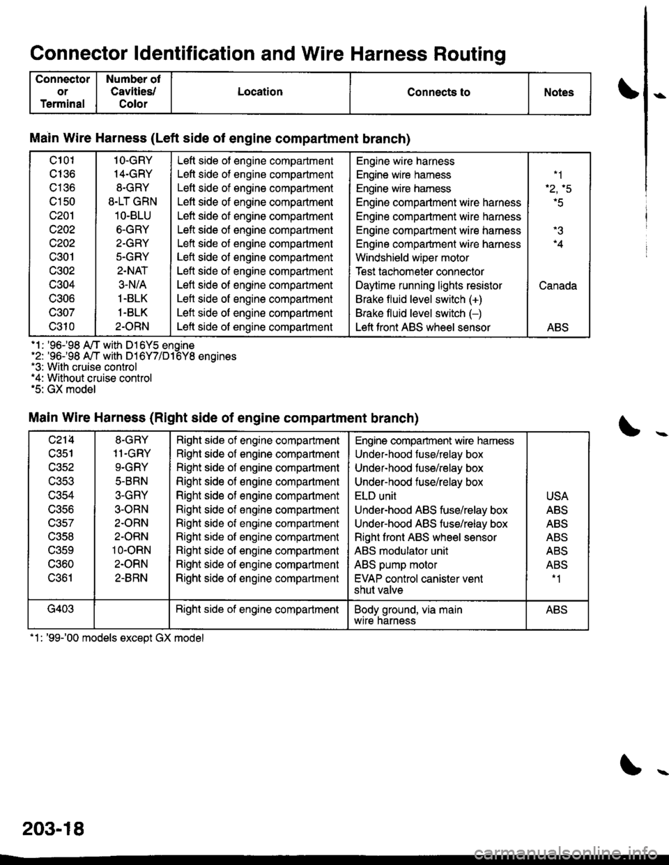
Connector ldentification and Wire Harness Routino
Connector
or
Terminal
Number ot
Cavities/
Color
LocationConnects toNotes
Main Wire Harness (Left side of engine compartment branch)
c101
cI36
c136
c150
c201
c202
c202
c301
c302
c304
UOUO
c307
c310
1O.GRY
14-GRY
8.GRY
8.LT GRN
1O-BLU
6.GRY
2-GRY
5.GRY
2.NAT
3-N/A
1.BLK
1-BLK
2.ORN
Left side ot engine compartment
Left side of engine compartment
Letl side of engine compartment
Lett side of engine compaftment
Left side of engine compartment
Left side of engine compartment
Left side of engine compartment
Left side of engine compartment
Left side of engine compartment
Left side of engine compartment
Left side of engine compartment
Left side of engine compartment
Left side of engine compartment
Engine wire harness
Engine wire hamess
Engine wire hamess
Engine compartment wire harness
Engine compartment wire harness
Engine compartment wire harness
Engine compartment wire harness
Windshield wiper motor
Test tachomeier connector
Daytime running lights resistor
Brake fluid level switch (+)
Brake fluid level switch (-)
Left front ABS wheel sensor
.1
'r.q
r5
.4
Canada
ABS
.1 : '96-98 A/T with D16Y5 enoine'2: '96-98 A,/T with D16Y7/D16Y8 enoines.3: With cruise control*4: Without cruise control.5: GX model
Main Wire Harness (Right side of engine compartment branch)
c214
c351
wacl
UJCJ
c356
c357
c358
UOCY
c360
c361
8-GRY
11.GRY
9.GRY
5-BRN
3-GRY
3-ORN
2.ORN
2-ORN
10-oRN
2.ORN
2-8RN
Right side of engine compartment
Right side of engine compartment
Right side of engine compartment
Right side of engine compartment
Right side of engine compartment
Right side of engine comparlment
Right side ot engine compartment
Right side ot engine companment
Right side of engine compartment
Right side of engine compartment
Right side of engine compartment
Engine compartment wire hamess
Under-hood fuse/relay box
Undef-hood tuse/relay box
Under-hood fuse/relay box
ELD unit
Under-hood ABS fuse/relay box
Underhood ABS fuse/relay box
Right front ABS wheel sensor
ABS modulator unit
ABS pump motor
EVAP control canister vent
shut valve
USA
ABS
ABS
Al'D
AE5
ABS-1
G403Bight side of engine compartmentBody ground, via mainwtre narnessABS
.1: '99-'00 models except GX model
203-18
Page:
< prev 1-8 9-16 17-24