Page 767 of 2189

Troubleshooting Flowchart - Shift Control Solenoid Valve A
NOTE: Record allJreeze data before you troubleshoot.
Possible Cru3.
' Disconnectod 3hift control
solonoid valva A/B a33emblY
connactot. Short or opon in shift cont.ol
solonoid valvo A wits. Faulty shift control .olenoid
. op.n in vB SOL wi.e
To page 14-90
PCM CONNECTOBS
LG1{BRN/BLK} LG2IBRN/BLKI
Wire side of female terminals
LGl IBRN/BI-K)LG2IBBN/BLK)
. OBD ll Scan Tool indic.ts6 Code
Pot53.. Solt-diagno.is E indicrtot light
blinks seven time6.
Chock tor a Short to Power:
1. Turn the ignition switch OFF.
2. Disconnect the g (25P) and D(16P) conneclors from the
PCM,3. Turn the ignirion switch ON (ll)
,1. Measure the voltage between
the D7 and 820 or 822 termi
nals,
Rcpair short to powet in the wile
b€t^reen tho D7 termin.l .nd the
shift control aolonoid valve A.
Mee3ur. Shift Control Solonoid
Valve A Roaisttnce:1. Turn the ignition switch OFF.
2. Measure the resistance
between the D7 and 820 or
822 terminals.
ls the resistance 12 - 25 O?
Me.3uro vB SOL Voh.ge:1. Turn the ignition switch ON (ll).
2. Measure the voltage betweenthe D5 and 820 or 822 termi-
nals.
Check tor blown No. 15 17.5 A)
fuse in tho underdaah fula/rol.Ybox. ll the tusr is OK, .epair oPenin th. wiio betwe.n the D5 ter'min.l and th. underdssh tuso/relav box.
ls there baftery voltage?
Check for loose t6tminalfit in th€
PCM connoctors. It necessary,substitute e known-good PCMand rechock.
I t25Pt ll D {16P)
B rzsPt o trQil
(cont'd)
14-89
Page 769 of 2189

Troubleshooting Flowchart - Shift ControtSolenoid Valve B
NOTE: Record all freeze data before you troubleshoot.
Possiblg Cause
. Disconnectgd ihilt control
solenoid valve A/B conneciotr Short or oDen in shift conlrol
3olgnoid vrlve B wito. Faulty 3hift control solenoid
velve B. Op€n in VB SOL wirercM CONNECTORS
LGlIBRN/BLKI LG2IBRN/BLK)
Wire side of {emale terminals
LGi (BRi|/BLKILG2 IBRN/8LK)
To page 14-92
(cont'd)
14-91
. OBD ll Scan Tool indic.l6 Code
P0758.' Self-diagnosb El indicator light
blinks eighl tim6.
Check tor a Shortto Power:
1. Turn the ignition switch OFF
2. Disconnect the B (25P) and D(16P) connectors from the
PCM.3. Turn the ignition switch ON (lli.
4. Measure the voltage between
the D2 and 820 or 822 termi
nals,
Repaft 3hon to Powor in the wir€
b€tirvoon the D2 termin.l and the
3hift control solenoid valve B.
M€asure Shift Control SolenoidValve B R6isttnce:1. Turn the ignition switch OFF
2. Measure the resistance
between the D2 and 820 or
822 terminals.
ls the resistance 12 - 25 O?
Me.sure VB SOL Vohage:1. Turn the ignition switch ON (ll).
2. Measure the voltage betweenthe D5 and 820 or 822 termi'
nars.
Check lol blown No 15 {7.5 Al
fuse in the under-d.sh luae/rolav
box. ll the fuse is OK, repair open
in ihe wire between tho D5 ter-
minal and the under'dash fus€/relav box.
ls there battery voltage?
Check for loo3e terminal fit in the
PCM connectols. lf necossarY,
substitute a known_good PCM
and rocheck,
B (25Pt - I lD {16P)
B {25P1 D (t6Pl
Page 775 of 2189

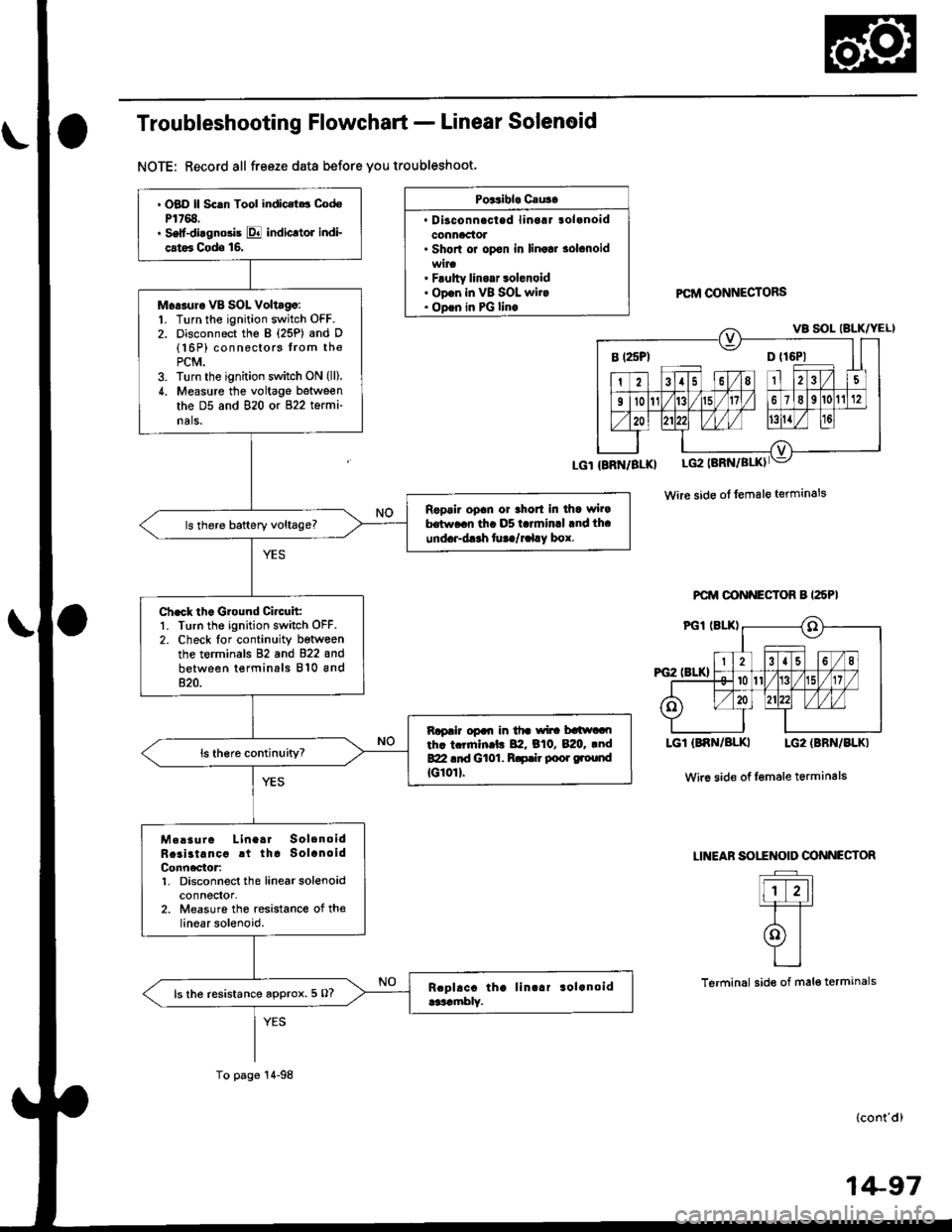
Troubleshooting Flowchart - Linear Solenoid
NOTE: Record all freeze data before you troubleshoot.
Poitibl. Cau3.
. Disconnacted linoaJ tolanoidconnaclol. Shorl or opon in linolr solonoid
. Flulty linoar 3olenoid. ODon in VB SOL wit.. ODen in PG linoPCftI @NNECTORS
Wire side ol female terminals
PCM OONNECTOR B I25PI
LGT (BNN/BLKI LG2 {BBN/BLKI
Wir6 side of Iemale terminals
LINEAF SOITNOID OONNECTOR
Flr-11=T=T
olYI
L_l
Terminal side of mal€ termanals
(cont'd)
B t25Pl D {16P1
. OBD ll Scln Tool indic.t.t CodoP1768.. Self-diagnosis E indicltol indi-
cat6 Cods 16.
Moasur. VB SOL Voltago:1. Turn the ignition switch OFF.2. Disconnect the B {25P) and D(16P) connectors from thePCM.3. Turn the ignition switch ON (lll.
4. Measure the voltage between
the D5 and 820 or 822 termi-
nals.
Ropair opan or thort in dla wi.9hrw..n th. D5 t.rminrl .nd th.
und.r-d.rh fu ta/r.l.y box.
Ch.ck th. Ground Circuit:1. Turn the ignition switch OFF.2. Check lor continuity betwoenthe terminals 82 and 822 and
between terminals 810 and820.
Rapair opal| in tfr wi|! batlwaoth. tcrrnln.l. 82, B10, B:20. .ndBZI .id Gt01. R.p.ir poor ground
tG10rl.
M.!sure Linea. SolenoidRcai3tancc rt tha SolanoidConn6ctor:1. Disconnect the linearsolenoidconnectol,2. Measure the resistance of thelinear solenoid.
ls the resistance approx. 5 O?
To page 14-98
1+97
Page 777 of 2189

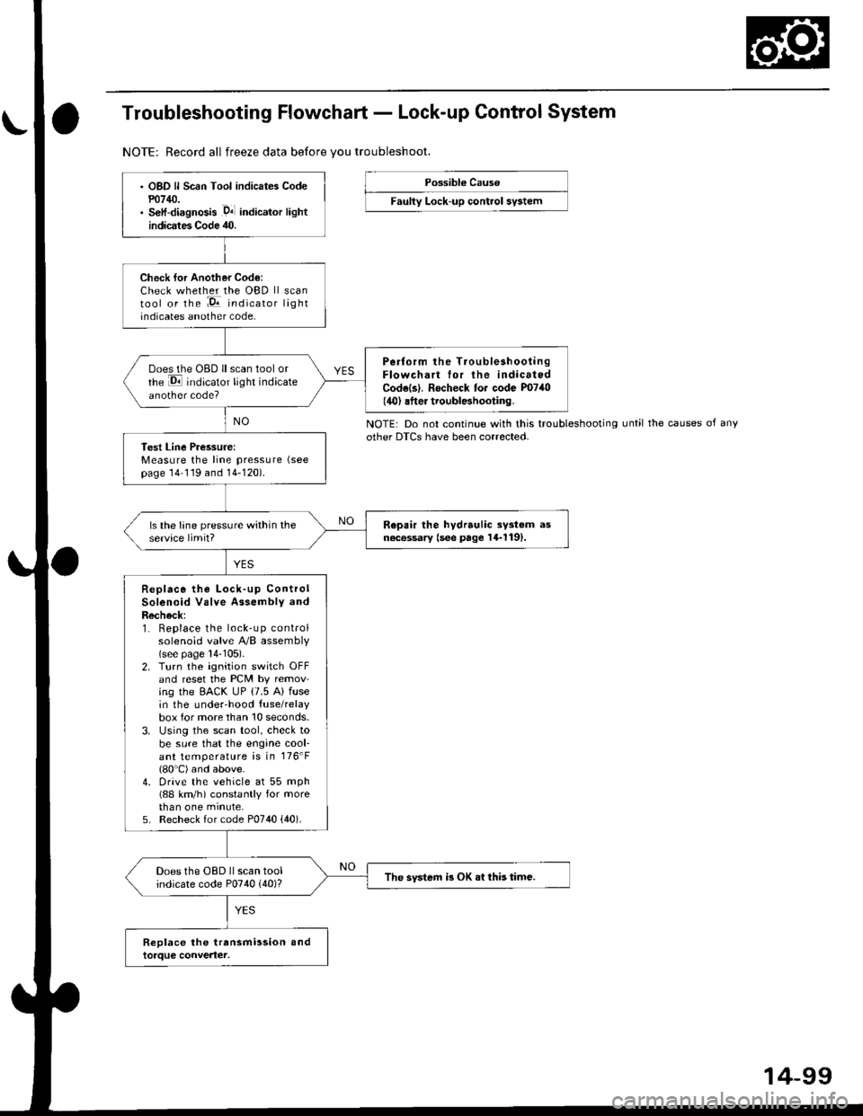
Troubleshooting Flowchart - Lock-up Control System
NOTE: Record all freeze data before vou troubleshoot.
Possibl€ Cause
Faulty Lock-up control sy3tem
NOTE: Do not continue with this troubleshootingother DTCS have been corrected.until the causes of any
OBD ll Scan Tool indicates Codem14/J.S€lf-diagnosis .D4l indicalor lightindicates Code 40.
Check for Another Code:Check whether the OBD ll scantool or the :E indicator lightindicates another code,
Perform the TroubleshootingFlowchart tor the indicatedCodels|. Rocheck to. code P0740(40) .fter troublBhooting.
ooes the OBD ll scan tool orrhe E indicator light indicateanother code?
Test Line Pressure:Measure the line pressure (see
page 14 119 and 14-120).
Repair the hydrrulic sy3tem asn6c6ssary (see page 14-1191.ls the lane pressure within theservice limit?
Replace the Lock-up ControlSolenoid Valve Assembly andRecheck:1. Replace the lock-up controlsolenoid valve A/B assembly(see page 14-105).2. Turn the ignition switch OFFand reset the PCM by removing the EACK UP (7.5 A) fusein the underhood {use/relaybox for more than 10 seconds.3. Using the scan tool, check tobe sure that the engine cool-ant temperature is in 176'F(80'C) and above.4. Drive the vehicle at 55 mph(88 km/h) constantly for morethan one minute,5. Recheck for code P0740 {40).
Does the OBD ll scan toolindicate code P0740 (40)?The svstem i3 OK .t this time.
14-99
Page 778 of 2189

Electrical Troubleshooting ('99 - 00 Modelsl
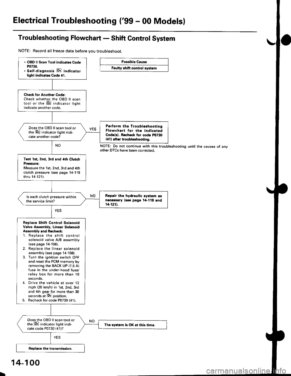
Troubleshooting Flowchart - Shift Control System
NOTE: Record allfreeze data before you troubleshoot.
Po33ibl. Crus6
Frulty 3hift control ryrtom
. OBD ll Scan Tool indicrtd Codem730.. Self-dirgnosis E indicatorlight indicst€. Codo 41.
Check for Anoth€. Code:Check whether the OBD ll scantool or the E indicator lightindicate another code.
Prrf orm tho Troublc!hootingFlowch.rt for th. indicrt.dCod.l3l. R.ch.ck tor cod. m730141| .tt r troubldhootlng.
Doesthe OBD llscan tool orthe E indicator light indi-cate another code?
Test 13t, 2nd, 3rd .nd 4th ClutchPrglture:Measure the 1st, 2nd,3rd and 4thclutch pressure (see page 14-119thru 14 121).
R.prir tho hydrlulic ayrtam aan.c.3t..y lr.o p!9. lil-119 rnd1+1211.
ls each clutch pressure withinthe service limit?
Roplace Shift Control SolenoidValve Asembly. Linoar Sol.noidAssembly .nd Recheck:1. Replace the shift controlsolenoid valve A/B assembly(see page 14-106).2. Replace the linear solenoidassembly {see page 14-108}.3. Turn the ignition switch OFFand reset the PCM memory byremoving the BACK UP (7.5 A)fuse in the under-hood fuse/relay box for more than 10seconds,4. Drive the vehicle at over 12mph (20 kn/h) in 1st, 2nd, 3rdand 4th gear lo. more than 30seconds at lPll position.5. Recheck for code P0730 (41).
Doesthe OBD Ilscan tool orthe E ;ndicator light indi-cate code P0730 (41)?Th. sFtcm b OK .t this time.
NOTE: Do not continue with this lroubleshooting until the causes ot anyother OTCS have beon corrected.
I
14-100
Page 779 of 2189

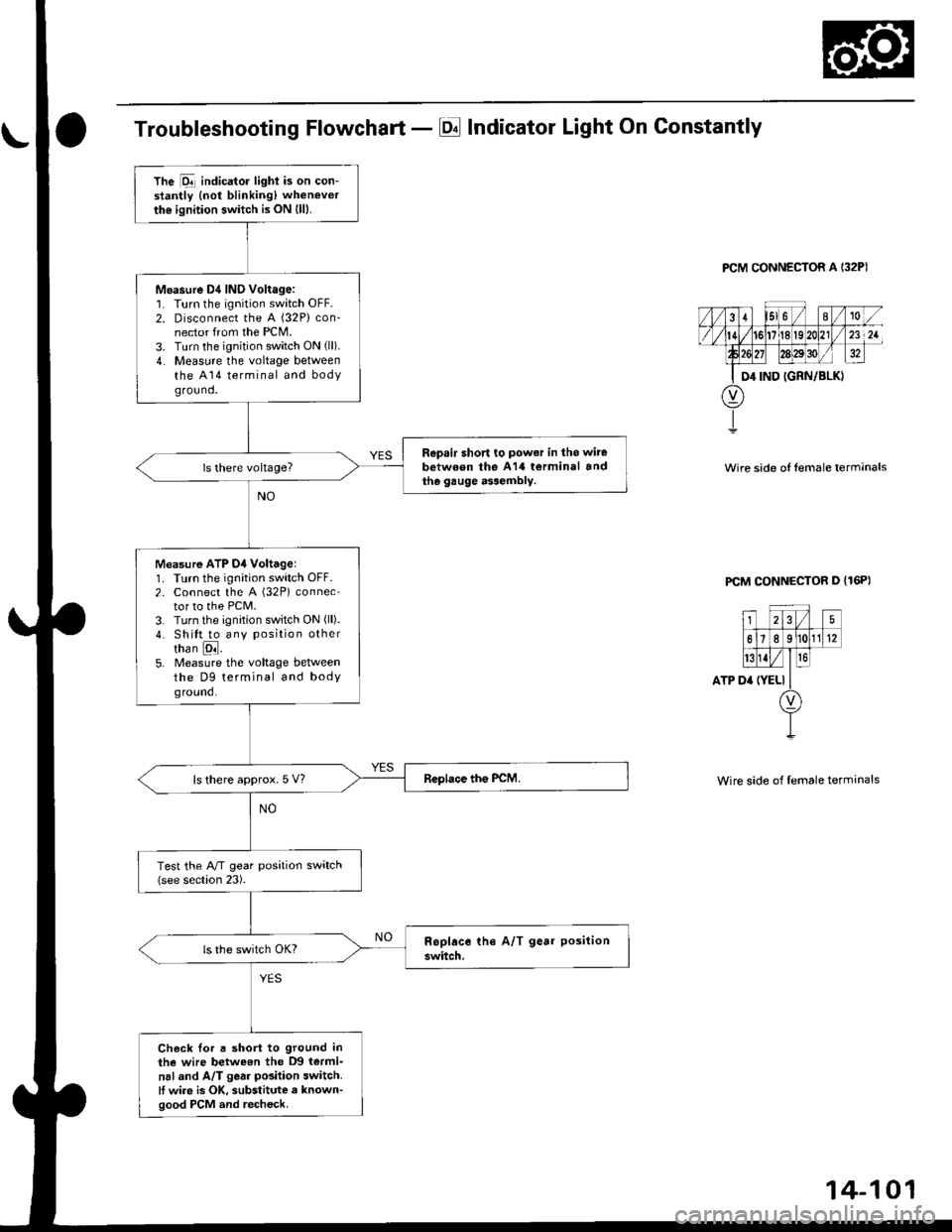
Troubleshooting Flowchart - El Indicator Light On Constantly
PCM CONNECTOR A I32P)
Wire side of lemale terrnanals
PCM CONNECTOR D {16P)
ATP D'
25
61e 11(12
t{Iro
(YELI
Wire side of female terminals
The Dll indicator lighi is on con-stantly {not blinking) whenever
the ignition switch is ON (lll.
Moasure D4 IND Voltage:1. Turn the ignition switch OFF.2. Disconnect the A {32P} con-nector from the PCM.3. Turn the ignition switch ON (ll).
4. Measure the voltage betweenthe A14 terminal and bodyground.
Repsir short to power in the wire
between the A14 torminal andthe gauge assembly.
Measure ATP D4 Voltagel1. Turn the ignition switch OFF.2. Connect the A (32P) connector to the PCM.3. Turn the ignition switch ON (ll).
4. Shitt to any position othertha n [ql.5. Measure the voltage betweenthe D9 terminal and bodyground.
ls there approx. 5 V?
Test the A/T gear position switch(see section 23).
Check Ior a short to ground inthe wire betweon the D9 termi-
nal and A/T gear position switch.It wire is OK, substitute a known-good PCM and recheck.
Page 780 of 2189

Electrical Troubleshooting ('99 - 00 Models)
Troubleshooting Flowchart - E Indicator Light Does Not Come On
FCM CONNECTOR B (25P}
LGl {8RN/ALKI{BRN/8LK}
Wire side ol temale terminals
LGl IBNN/BLK} LG2 {BRN/BLK)
i2t5 6q
910t7
LG2
o) (o
The Pll indicator light does notcome on when the ignitionswitch is fi.st turned ON (ll). lltshould come on for about twoseconda.l
Check the Service Check Con-nector:Make sure the special tool (SCS
Service Connector) is not connect-ed to the service check connector?
ls the specialtool {SCS ServiceConnector) is not connected tothe seNice check connector.
Disconnect the special tool fromthe service check connector andr6check.
Check the Dll lndicator LightiShift to d position.
Check for loose terminal fit in thePCM connecto13. It necessary.sub3titute a known-good PCMand recheck.
Does the @ indicator lightcome on?
Check the Ground Circuit:1. Turn the ignition switch OFF.2. Disconnect the B (25P) con-nector from the PCM.3. Check for continuity betweenthe 820 terminal and bodyground, and between the 822terminal and body ground.
Repair open in the wiresbetween the B20 rnd 822 termi-nals and ground (G101), andrep.ir poor ground (G1011.
Measure Power Supply CircuitVoltage:1. Turn the ignition switch ON {ll}.2. Measure the voltage betweenterminals B1 and 822 andbetween terminals Bg and820.
Repair open or short in the wi.obetween th6 81 and/or 89 termi-nals and the PGM-FI main relav,and between th€ PGM-FI mainr€ley rnd the under-hood tus€/relay box.
To page 14''103
14-102
Page 781 of 2189
From page 14-102
Measu.e D4 IND Voltago:1. Turn the ignition switch OFF.2. Connect the B (2SPiconnector
to the PCM.3. Connect a digital multimeter
to the A14 and 820 or 822 ter-
4. Turn the ignition switch ON (ll),
and make sure that voltage isavailable for two seconds.
Chock for ooon in tho witebetween the A't4 tsrminal .ndthe gauge.3s.mbly. ll wite i3OK, chock to. a t.ulty indicatorlight bulb or. feulty gaugc
e336mbly p.inted circuit board.
Check D4 IND lor a Short Citcuit:Check lor continuity between theA14 terminal and body ground.
Rop.ir short in thc wirg b€twoenth. Al4 tormin.l .nd tho gaugo
a$ombly. ll wiro is OK. chocktho gsugo a3rambly.
ls there continuity?
Check fo. loose terminal tit in thcPCM connectoB. Chock the A/Tgear position switch. It ncce3-sary, substitute a known-goodPCM and rechock.
PCM CONNECTORS
Wire side ol female terminals
14-103