2000 HONDA CIVIC lock
[x] Cancel search: lockPage 759 of 2189

From page 14-80
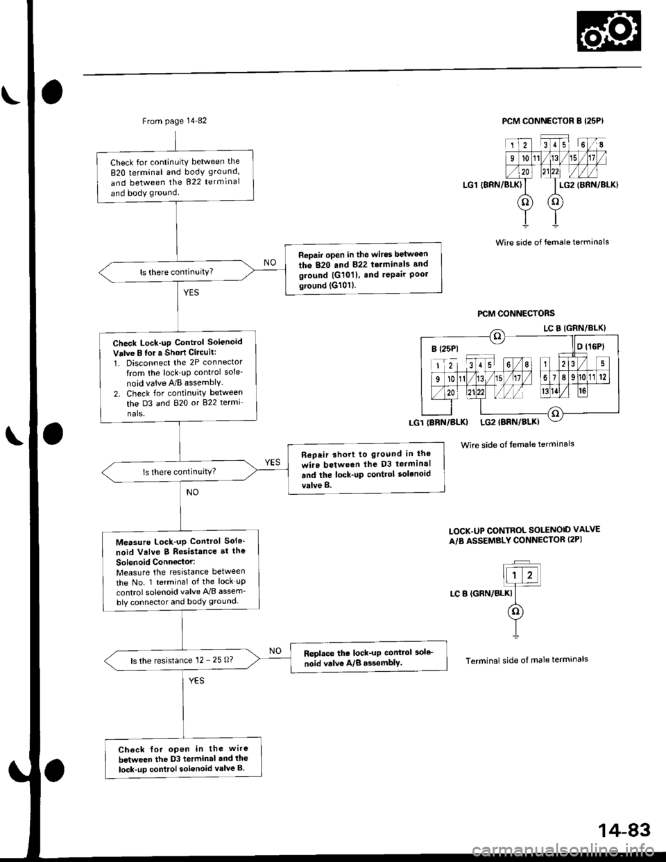
Check lor continuity between the
820 terminal and body ground,
and between the B22 terminal
and body ground.
Ropair opon in thc wircs betwe6n
the 820 lnd 822 tolminals .ndground {G10ll, and tepair Poolground (G10'l).
Check Lock-up Cont.ol Solonoidvalve A for a Shon Cilcuit:1. Disconnect the 2P connectortrom the lock-up control sole-
noid valve ry'B assembly.
2. Check for continuity betlv€en
th6 D1 and 820 or 822 termi-
nals.
R6p.ir 3hort to glound in thc
wir. b.two.n the Dl torn|in.l
ard th. lock-up conttol iol.noid
valva A.
Maasuro Lock-up Control Sol.-
noid Vllve A Ro.istance at tho
Solanoid Conn6ctor:Measure the resistance between
the No. 2 terminal of the lock-up
control solenoid valve y'y'B assem-
bly connector and body ground.
R6placo tho lock-up control solo_
noid valve A/B.$6mblY.ls the resistance '12 - 25 O?
Chack for opon in tho wiro
botweon the Dl t..minal and tho
lock-up control solenoid Yalva A.
PCM CONNECTOR B {25P}
I.G1 (BRN/BLKI
Wire side of l6male terminals
PCM OONI{ECTORS
Wire side ot female terminals
LOCK.UP CO TROL SOTINOID VALVEA/B ASSEMBLY CON]TECTOR I2P}
]F]ALr-f-
I LC A {YEu
(o�)Y
I
Terminal side of male terminals
B (25p) ll o l16P)
IBRN/BLK} LG2IBRN/BLK}
14-A1
Page 760 of 2189

Electrical Troubleshooting ('99 - 00 Models)
Troubleshooting Flowchart - Lock-up Control Solenoid Valve B
NOTE| Record allfreeze data before you troubleshoot.
Possibla Cause
. Oisconnected lock-uD controlsolenoid velve A/B assemblyconnector. Short or open in lock-up controlsolenoid valv€ B wire. Faulty lock-up control solenoidvalve B' Open in VB SOL wirercM CONNECTORS
To page 14-83
' OBD ll Scan Tool indic.tes CodeP1758.. Self-diagnosis E indicatorlight blinks twice.
Chack for a Short to Power:1. Turn the ignition switch OFF.2. Disconnect the I (25P) and D(16P) connectors from thePCM.3. lurn the ignition switch ON (ll).4. Measure the voltage betweenthe D3 and 820 ot 822 tetmi-nals,
Repair short to power in the wirebetween the D3 terminal and thelock-up contlol solenoid valve B.
Measure Lock-up Control Sole-noid Vdlve I R8i3tance:1. Turn the ignition switch OFF.2, Measure the resistancebetween the D3 and 820 or822 terminals.
ls the resistance 12 - 25 O?
Measure VB SOL Voltago:1. Turn the ignition switch ON lll).2. Measure the voltage betweenthe D5 and 820 or 822 termi-nals.
Check for blown No. 15 {7.5 Alfus€ in the under-dash luse/releybox. It the fuse is OK, repair openin the wir6 between th6 DS terminal and the under-dash fuse/rebyoox,
ls there battery voltage?
Chock for loose te.minal fit in thePCM connectors. It necessary,substitute a known-good PCMend recheck.
B t2sP) ll D t15P)
Wire side ol female terminals
I {2sPt ll D (16Pt
B (25P1 D t16Pt
\
14-82
Page 761 of 2189

From page 14-82
Check for continuitY between the
820 terminal and body ground,
and between the 822 terminal
and body ground
Repair open in the wires between
the 820 and 822 terminals and
ground |G101), and repair Poolground (G1011.
Check Lock-up Control Solenoid
Valve B lor a Short Cilcuit:
1. Disconnect the 2P connector
from the lock_uP control sole-
noid vaive A/B assemblY.
2. Check for continuity between
the D3 and 820 or 822 termi
nals.
Rep.ir short to ground in lho
wire between lhe D3 terminal
and the lock-up contlol solenoid
valve B.
Measure Lock-up Control Sol6'
noid Valve B Resistance at the
Sol6noid Conn€ctor:Measure the resistance between
the No. 1 terminal of the lock uP
control solenoid valve A'lB assem_
bly connector and body ground-
Repl.ce the lock-up control 3olc
noid valve A/B a$emblY.ls the resistance 12 - 25 0?
Ch6ck {or open in the wire
between the D3 terminal dnd ihe
lock-up control sol€noid valve B.
PCM CONNECTOR B (25PI
LG1 (BRN/BLK)
2351 6I
l011/15
LG2
oo
(BRN/BLKI
Wire side of female terminals
Wire side of female terminals
LOCK.UP CONTROL SOLENOID VALVE
A/B ASSEMBLY CONNECTOR (2PI
t;T�Jllt z!]4
LC B (GRN/BLKI It(o)
YI
Terminal side of male termrnals
B (25P1 - llo t16Pt
14-83
Page 777 of 2189

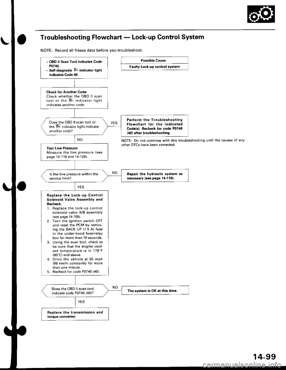
Troubleshooting Flowchart - Lock-up Control System
NOTE: Record all freeze data before vou troubleshoot.
Possibl€ Cause
Faulty Lock-up control sy3tem
NOTE: Do not continue with this troubleshootingother DTCS have been corrected.until the causes of any
OBD ll Scan Tool indicates Codem14/J.S€lf-diagnosis .D4l indicalor lightindicates Code 40.
Check for Another Code:Check whether the OBD ll scantool or the :E indicator lightindicates another code,
Perform the TroubleshootingFlowchart tor the indicatedCodels|. Rocheck to. code P0740(40) .fter troublBhooting.
ooes the OBD ll scan tool orrhe E indicator light indicateanother code?
Test Line Pressure:Measure the line pressure (see
page 14 119 and 14-120).
Repair the hydrrulic sy3tem asn6c6ssary (see page 14-1191.ls the lane pressure within theservice limit?
Replace the Lock-up ControlSolenoid Valve Assembly andRecheck:1. Replace the lock-up controlsolenoid valve A/B assembly(see page 14-105).2. Turn the ignition switch OFFand reset the PCM by removing the EACK UP (7.5 A) fusein the underhood {use/relaybox for more than 10 seconds.3. Using the scan tool, check tobe sure that the engine cool-ant temperature is in 176'F(80'C) and above.4. Drive the vehicle at 55 mph(88 km/h) constantly for morethan one minute,5. Recheck for code P0740 {40).
Does the OBD ll scan toolindicate code P0740 (40)?The svstem i3 OK .t this time.
14-99
Page 783 of 2189

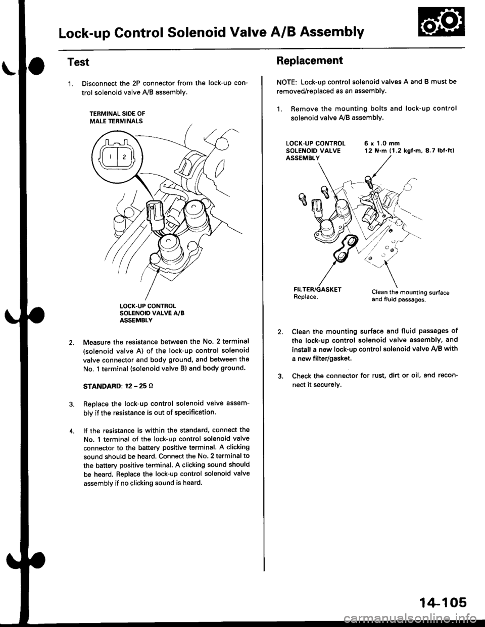
Lock-up Gontrol Solenoid Valve A/B Assembly
Test
'1, Disconnect the 2P connector from the
trol solenoid valve 1y'8 assembly.
TERMINAL SIOE OF
MALE TERMINALS
tocK-up con-
LOCK.UP CONTROLSOLENOID VALVE A/BASSEMBLY
Measure the resistance between the No. 2 terminal
(solenoid valve A) of the lock-up control solenoid
valve connector and body ground, and between the
No. 1 terminal (solenoid valve Bl and body ground.
STANDARD: 12 - 25 O
Replace the lock-up control solenoid valve assem-
bly if the resistance is out of specification.
lf the resistance is within the standard, connect the
No. 1 terminal of the lock-up control solenoid valve
connector to the battery positive terminal. A clicking
sound should be heard. Connsct the No. 2 terminal to
the battery positive terminal. A clicking sound should
be heard. Replace the lock-up control solenoid valve
assembly if no clicking sound is heard.
Replacement
NOTE: Lock-up control solenoid valves A and I must bs
removed/replaced as an assembly.
1. Remove the mounting bolts and lock-up control
solenoid valve Ay'B assemblv.
6 r 1.0 mm12 N.m (1.2 kgf.m,8.7 lbl.ftl
/:'-
Clean the mounting surfaceand fluid psssages.
Clean the mounting surface and fluid passages of
th6 lock-up control solenoid valve assembly, and
instsll a new lock-up control sol€noid valve Ay'B with
a new filtsr/gask€t.
Check the connector for rust, dirt or oil, and racon-
nect it securely.
1+105
Page 787 of 2189

Symptom-to-Component Chart
Hydraulic System
SYMPTOMCheck these items on the Check lhese lems on
PROBABLE CAUSE List the NOTES LIst
Engine runs, but vehicle does not move in any gear.1.2,3,5,6,7.36,38 K, L, R, S
Vehicle moves in E, E, but not in lrl, pr-, position.6, 8, 9, 10, 30, 54c,M,o
Vehicle moves in Dl, E, El,lut not in E position.6,11,12.24C,L
Vehicle moves in -o1], @, @, Uut not in E position.4, 6, 14, 15c,L,o
Vehicle moves in E position.10, 12, 13,14, 16, 29, 33, 34, 35C,D
Excessive idle vibration.1.2, 19,32,36, 45, 41, 4a
Poor acceleration; flares on starting otf in E, [Dl] position
Stall rpm hiqh in !!1, p!1, E position.1,2,3,6,34, 41K,L,R
stall rom hioh in D.r, lD,l oosition.6. 8. 10C,D
5t"[ rprn rsn ^ a"t"t-at6,12C,D
14N
11 , 32. 45, 41 , 48
No shift19,20, 40, 48, 49G,L
Fails to shift in 81, pll position; from lst to 3rd gear22, 49
Fails to shift in 03, D. oosition; from lstto4th qear22.23, 48
Erratic upshifting.
1'2 upshift, 2-3 upshift, 3-4 upshift
1-2 upshift
3'4 upshift
58
21, 48
22, t9
23,la
Harsh upshift {1 2).12, 19, 20, 29. 50, 51, 57. 54
Harsh upshift (2'3).13, 19, 20, 24, 27 , 29, 50. 51 , 51 , 58C,D,E,H,L
Harsh upshift (3'4).14, 19, 20, 25, 28, 29. 50, 51 , 51 , IC, D, E, I,L
Harsh downshift (2-1)19, 20. 24, 43, 54, 57 , 58o
Harsh downshift (3-2).12, 19, 20,25, 43, 55, 57,5AC,D,E,H
Harsh downshift (4-3).13, 19, 20, 26, 43, 56, 57, 58C, D, E, I
Flares on 2-3 upshift.13, 19,20,24.21,51FI
Flares on 3-4 upshift.14, 19 . 20, 25. 24, 51E,L,N
Excessive shock on 2-3 uPshift.13. 19, 20, 24, 27 . 43. 50. 51 , 58E,L,N
Excessive shock on 3-4 uPshift.14, 19, 20, 25. 2A, 8, 50, 51 , 58E,L,N
Late shift from El position to Lq! or &l position.10, 30
Late shift from E position to E position.4, 14, 21,53o
Noise from transmission in all shift lever positions2,31K,L,O
Vehicle does not acceletate more than 31 mph {50 km/h)17
shift lever does not operate smoothly.6, 39P
Fails to shift; stuck in 4th gear.19, 48, 49
Transmission will not shift into park in [a] position6, 18, 39
Stall rpm high; all clutch pressures are in specification.41D,K,O
Lock up clutch does not disengage.19, 44, 45, 46. 41,50,51.54
Lock up clutch does not operate smoothly.19, 41, 44, 45, 46, 47, 50, 51, 58L
Lock-up clutch does not engage.19, 41, 4t, 15, 46, 41 ,50, 51, 57, 58FI
Vibration in all positions
(cont'd)
Page 789 of 2189

The following symptoms can be caused
by improper repair or assembly
Check these items,on th€^ ltems on thePROBABLE CAUSE DUE TO NOTES ListIMPROPER REPAIR List
Vehicle creeps in N position.R1, R2
Vehicle does not move in &l or Pll position.R4
Transmission locks up in E position.R3, R11
Excessive drag in transmission.R6K,R
Excessive vibration, rpm related.R7
Noise with wheels moving onlY.R5
Main seal pops out.R8
Various shifting problems.R9, RlO
PROBABLE CAUSE DUE TO IMPROPER REPAIR
lmproper clutch clearance.
lmproper gear clearance.
Park lever installed upside down.
one-way {sprag) clutch installed upside down.
Reverse selector hub installed upside down.
ATF pump binding.
Torque converter not fully seated in ATF pump.
Main seal improperly installed.
Springs improperly installed.
Valves improperly installed.
Shift fork bolt not installed.
14-11
Page 790 of 2189

Symptom-to-Component Chart
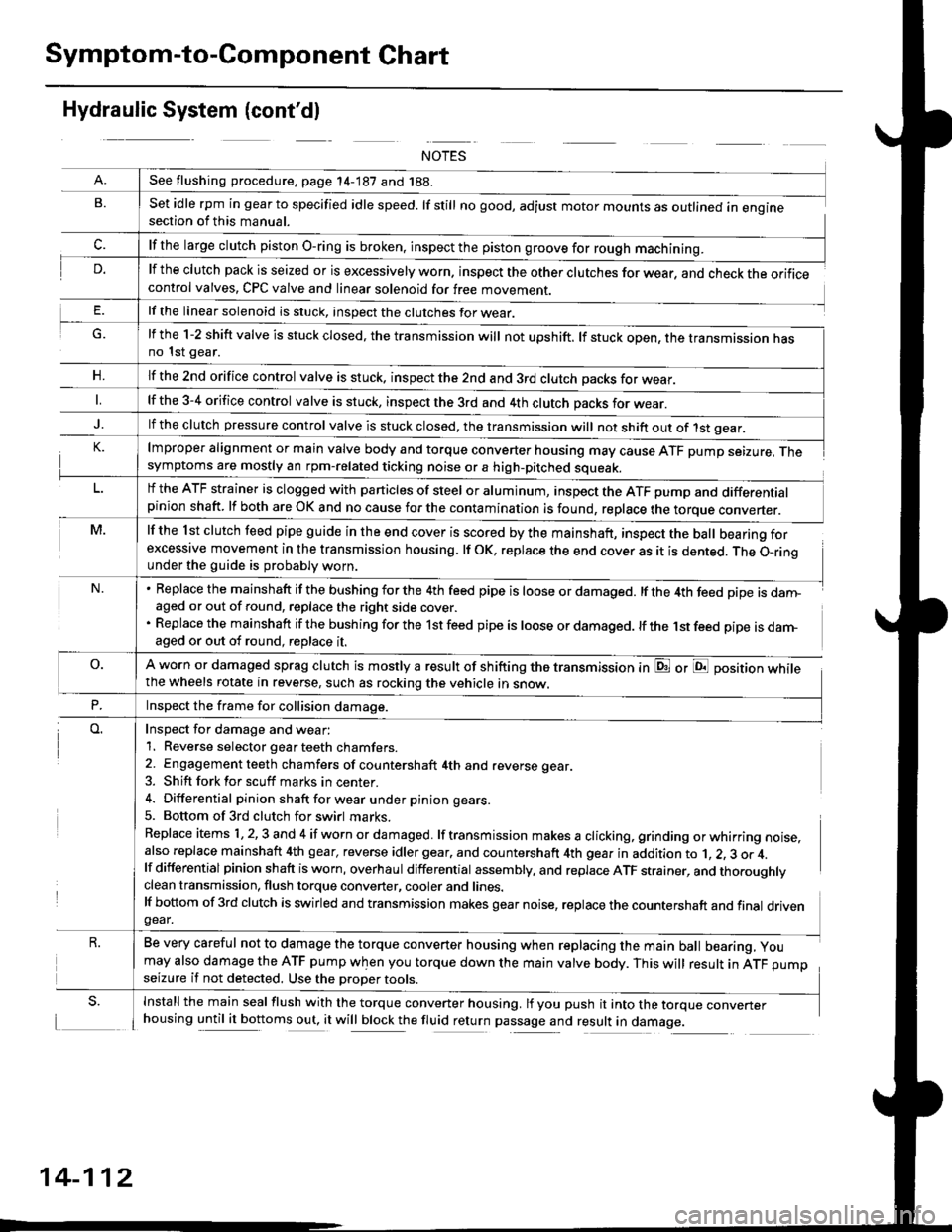
Hydraulic System (cont'dl
G.
n,
set idle rpm in gear to specified idle speed. lf still no good, adjust motor mounts as outlined in enginesection of this manual.
lf the clutch pack is seized or is excessively worn. inspect the other clutches for wear, and check the orificecontrol valves, CPC valve and linear solenoid for free movement.
lf the linear solenoid is stuck, inspect the clutches for wear.
lmproper alignment or main valve body and torque converter housing may cause ATF pump seizure. Thesymptoms are mostly an rpm-related ticking noise or a high-pitched squeak.
lf the l st clutch feed pipe guide in the end cover is scored by the mainshaft, inspect the ball bearing forexcessive movement in the transmission housing. lf oK, replace the end cover as it is dented. The o-rinounder the guide is probably worn.
Replace the mainshaft if the bushing for the 4th feed pipe is loose or damaged. lf the 4th feed pipe is danFaged or out of round, replace the right side cover.
Replace the mainshaft if the bushing for the 1st feed pipe is loose or damaged. lf the 1st feed pipe is darn-aged or out of round, replace it.
A worn or damaged sprag clutch is mostly a result of shifting the transmission inthe wheels rotate in reverse, such as rocking the vehicle in snow.
or E position while
Inspect for damage and wear:
1. Reverse selector gear teeth chamfers.
2. Engagement teeth chamfers of countershaft 4th and reverse gear.
3. Shift fork for scuff marks in center.
4. Differential pinion shaft for wear u nder pin ion gears.
5. Bottom of 3rd clutch for swirl marks.
Replace items 1,2,3 and 4 if worn or damaged. lf transmission makes a clicking, grinding orwhirring noise,also replace mainshaft 4th gear, reverse idler gear. and countershaft 4th gear in addition to 1, 2, 3 or 4.lf differential pinion shaft is worn, overhaul differential assembly, and replace ATF strainer, and thoroughlyclean transmission, flush torque converter, cooler and lines.lf bottom of 3rd clutch is swirled and transmission makes gear noise, replace the countershaft and final drivengear.
Be very careful not to damage the torque converter housing when replacing the main ball bearing, you
may also damage the ATF pump when you torque down the main valve body. This will result in ATF pumpseizure if not detected. Use the oroper roors.
Install the main seal flush with the torque converter housing. lf you push it into the torque converterhousing until it bottoms out, it will block the fluid return passage and result in damage.
See flushing procedure, page 14-187 and 188.
lf the large clutch piston O-ring is broken, inspect the piston groove for rough machining.
lf the l-2 shift valve is stuck closed, the transmission will not upshift. lf stuck open, the transmission hasno 1st gear.
lf the znd orifice control valve is stuck. inspect the 2nd and 3rd clutch oacks for wear.
lf the 3-4 orifice control valve is stuck, inspect the 3rd and 4th clutch oacks for wear.
lf the clutch pressure control valve is stuck closed, the transmission will not shift out of 1st gear.
lf the ATF strainer is clogged with particles of steel or aluminum, inspect the ATF pump and differentialpinion shaft. lf both are OK and no cause for the contamination is found, replace the torque converter.
Inspect the frame for collision damage.
14-112