2000 HONDA CIVIC ignition
[x] Cancel search: ignitionPage 351 of 2189
Troubleshooting
Troubleshooting Procedures (cont,dl
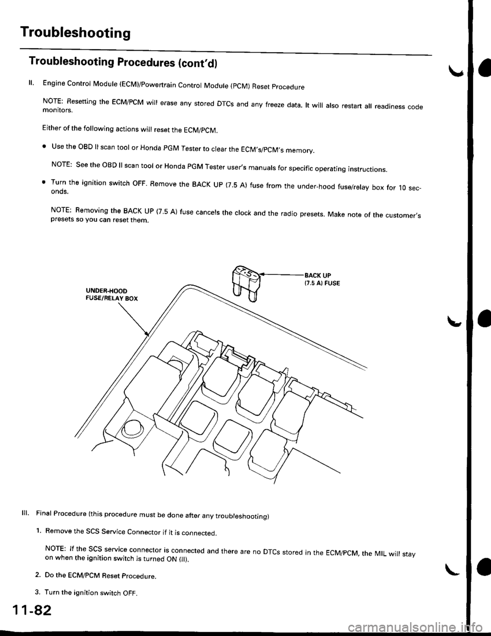
ll, Engine Control Module (ECM)/powertrain Control Module (pCM) Reset procedure
NoTE: Resetting the EcM/PcM will erase any stored DTcs and any freeze data. lt will also restart all readiness codemonitors.
Either of the following actions will reset the ECM/PCM.
. Use the OBD ll scan tool or Honda pGM Tester to clear the EClM,s/pCM,s memory.
NorE: see the oBD ll scan tool or Honda PGM Tester user's manuals for specific operating instructions.
' Turn the ignition switch oFF. Remove the BACK uP (7.5 A) fuse from the under-hood fuse/relay box for 10 sec-onds.
NorE: Bemoving the BACK uP (7 5 A) fuse cancels the clock and the radio presets. Make note of the customer,spresets so you can reset then
lll. Final Procedure (this procedure must be done after any troubleshoottng)
1. Remove the SCS Service Connector if it is connected.
NoTE: If the Scs service connector is connected and there are no DTcs stored in the EcMipcM, the MtL will stayon when the ignition switch is turned ON 0l).
2. Do the ECM/PCM Reset procedure.
3. Turn the ignition switch OFF.
1-82
Page 352 of 2189

lf the inspection for a particular code requires voltage or resistance checks at the ECM/PCM connectors, remove the right
kick panel. Pull the carpet back to expose the ECM/PCM. Remove the ABS control unit if so equipped. unbolt the EcM/
PCM bolt. Turn the ignition switch oFF, and connect the backprobe sets and a digital multimeter as described below
check the system according to the procedure described for the appropriate code(s) listed on the following pages'
The illustrationshows '96 - '98 models.
How to Use lhe Backprobe Sets
connect the backprobe adapters to the stacking patch cords, and connect the cords to a multimeter. using the wire insula-
tion as a guide for the contoured trp of the backprobe adapter. gently slide the tip into the connector from the wire side
until it comes in contact with terminal end of the wire'
BackProbe
BACKPROEE SET
07SAZ - 001000A lTwo
DIGITAL MULTIMETER(Commercially avail.bleI orKs - AHM - 32 - oo3 (cont'd)
KICK PANEL
1 1-83
Page 356 of 2189
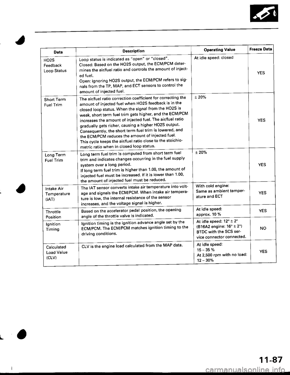
DataDescriotion
Loop status is indicated as "open" or "closed"'
Closed: Based on the HO2S output, the ECM/PCM deter-
mines the airlfuel ratio and controls the amount of inject-
ed fuel.
Open: lgnoring HO2S output, the ECM/PCM refers to sig-
nals from the TP, MAP, and ECT sensors to control the
amount of injected fuel.
The air/fuel ratio correction coefficient for correcting the
amount ot injected fuel when H02S feedback is in the
closed loop status When the signal from the HO2S is
weak, short term fuel trim gets higher, and the ECM/PCM
increases the amount of injected fuel The airlfuel ratio
gradually gets richer, causing a higher HO2S output
Consequently, the short term fuel trim is lowered, and
the ECMiPCM reduces the amount of injected fuel
This cvcle keeps the airlfuel ratio close to the stoichio-
metric ratio when in closed loop status'
Operating ValueF eeza Data
HO2S
Feedback
Loop Status
At idle speed: closed
YES
Short Term
Fuel Trim
! 20%
YES
Long Term
Fuel Trim
Long term fuel trim is computed from shon term fuel
trim and indicates changes occurring in the fuel supply
svstem over a long Period
lf long term fuel trim is higher than 1.00, the amount of
injecGd fuel must be increased. lf it is lower than 1 00'
the amount of injected fuel must be reduced'
! 20%
YES
lntake Air
Temperature
{IAT)
The IAT sensor converts intake air temperature into volt-
age and signals the ECM/PCM. When intake air tempera-
ture is low, the internal resistance of the sensor
increases. and the voltaqe signal is higher'
With cold engine:
Same as ambient temPer'
ature and ECTYES
At idle speed:
approx. 10 %YESThrottle
Position
Based on the accelerator pedal position, the open'ng
angle of the throttle valve is indicated
lgnition
Timing
lgnition timing is the ignition advance angle set by the
gCV/eCV. tn" gCU/PCM matches ignition timing to the
driving conditions.
CLV is the engine load calculated from the MAP data'
At idle speed: 12'i 2'
(81642 engine: 16" t 2")
BTDC with the SCS ser-
vice connector connected.
NO
Calculated
Load Value
{CLV)
At idle speed:
15-35%
At 2.500 rpm with no load:
12 - 30%
YES
ro
11-87
Page 357 of 2189
Troubleshooting
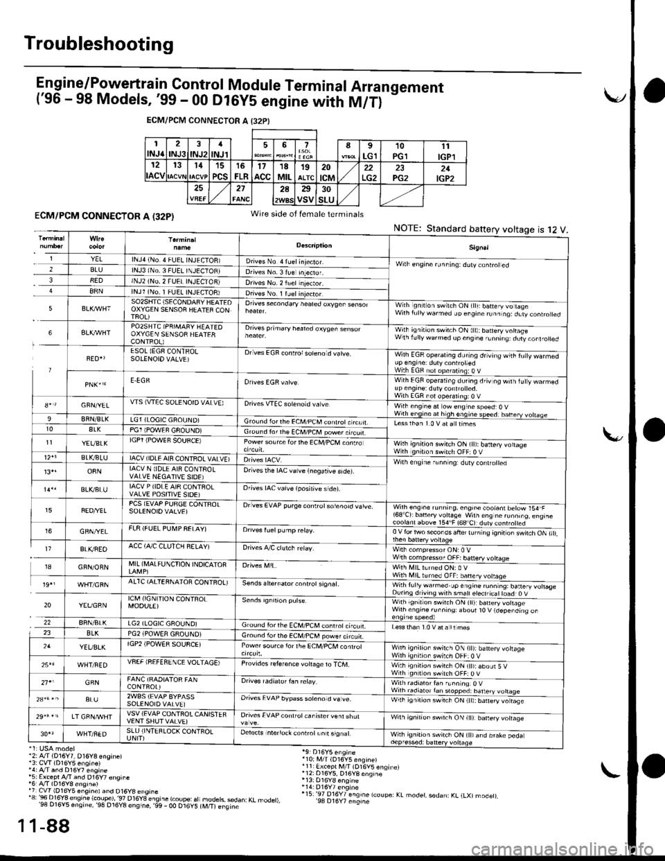
E n gine/P_o,weft ra in Control Module Term inal Arra n gement('96 - 98 Models, '99 - 00 Dl6yS engine with M/T)
-
ECM/PCM CONNECTOR A I32PI
1INJ62INJ3INJ21
INJl567I
LG110PGll1
IGPl12
ACV
131115
PCS
16
FLR17acc18MIL19ALTC20
tcM22PG221IGP2272A25
VSV30
SLU
ECM/PCM CONNECTOR A (32P)
'2: A./T (D16Y7, 016Y8 engine)13: CvT (D16Y5 enoin€)',4: A/T and D16y7 engine*5: Except A/T and D16Y7 €nsine'6r A/T (D16Y8 ensine)'7 Cw 1D16Y5 eng,nel and D16y8 ensrne'"'3:Bi..I?'Jt;".'e'.!ti.?i?l'""."T8"_";btfr
"fl
1-88
Wire side of female terminals
NOTE:Standard battery voltage12ts
'10i i,4/T (D16V5 engine)r11 Ex.ept M/l (D16V5 enqinelr12: 016Y5, D16YB enqine
r15:'97 016Y7 engine lcoupe: KL modet, sedan: KL (LXl modet),'98 D16Y7 engine
1
1
Sign.l
YELlNJ4 (No.4 FUEL INJECIOB)D ves No 4 ruel injector.Wilh engine runninq: ddly coniroted2BLUlNJ3 lNo. 3 FUEL TNJECTOBJDrives No. 3 lue Inteclor.38EDINJ2 (NO, 2 FUEI INJECTON)Drives No. 2 iuel njector.88NlNJl (No. 1 FUEL INJECTOB)Dives No. 1 ruelinjector.
5SO2SIITC (SECONDAFY HEATEDOXYGEN SENSOF HEATEF CONTFOL)
Orives secondary heated oxyqen sensorWith ignilion switch ON (lll: batery vo lageWith f!llywarmed up engine runninq:dLtv controled
6BLXAVHTPO2SHTC (PRIMAFY HEATEOOXYGEN SENSOR HEATERCONTROL)
Drives prihary healed oxygen sensorWith ignition switch ON ltt):baneryvottasewlhrdllywdrmedupcngne,Lnnrrq dury,orl.otred
FED{ESOL (EGF CONTRO!SOIENOIO VALVE)Drives EGF conlrolsoleno d vatve.Wilh EGR operating during drving wiih fu|y warmedup engrne: duty controttedWilh EGF nol opefating:O VE.EGRWith EGF operating du.ing driv og wilh iuty warmedup en9ine: dutycont.olted.With EGR not ooeralino; o V8*r/GFN/YELWS (VTEC SOLENOTD VALVE)Drives VTEC solenoid va veWilh eng ne at ow engine speed:O VWirh engine at h gh enqine speedr banery vohaae9BflN/BLKLG1 (LOGIC GROUND)Gro!nd lorthe €CM/PCM conlrotc rcuit.Lesslhan 1.0 V at a ttimest0ALKPG1 IPOWEF GFOUND)Ground ior rhe ECM/PCM power.tcuf.11YEVBLKIGPT iPOWEF SOUFCE)Power source forthe Ec[,l/PcM conlroWilh ignition swirch ON (tt): battery voltageWith gntron switch OFF: 0 VBLVBLUIACV (IDLE AIN CONTROL VALVE)Wilh engine r!nn ng: dlty contro ed13,.o8NIACV N lIDLE AI8 CONTFOLVALVE NEGATIVE SIOE)Drivesthe IAC valve {negalive side).
BLVBLUIACV P (IDLE AI8 CQNTROLVALVE POSITIVE SIDE)Orives IAC vaive (posilive side).
FEO/YELPCS (EVAP PURGE CONTFOTSOIENOIOVALVE)Drives EVAP pu.ge controtsolenoid vatve.Wilh engioe running, engin€ cootani betow 154,F'68'Cr bancry vohaSe w'ln ens nc runn,.o. eng,rc
GRN/YELFL8 (FUEL PU[4P FELAY)Orives fuelpump relay.0 V {or two secor os ahe' tJ n ng 'onir or \wnch ON ,,,,,
I7BLI(REOACC (A,/C CLUTCH RELAY)Drives A/C clutch relay.Wirh compressor ONr0 VWilh compressof OFF:banery votrage18GFN/ONNMIL (I\,lALFUNCTION INDICATOFWith MIL lLrned ON: 0 VWith illl turned OFF: banery volaqe19',AITC {AITERNAIOR CONIROL)se.ds ahernator controt signat.Wirh fully warmed.up engine ru.ntng: battery votlas€During drivins wnh smatl eteclricat toad: O V
20YEVGRNICM (IGNI'TION CONTROLMOOU!E)with ignltlon swilch ON (tl):b6n€ry vohageWilh ensine runnins: aboul t0 V (depending on
22BRN/BLKLG2 (LOGIC GAOUND)Ground for the ECM,/PCM conrrot ci'cu LLess than 1.0 V at a tt mes23BLKPG2 iPOWEA GROUND)Gro!nd lor the ECM/PCM power circuir.24YEUBLKlGP2 (POW€R SOUSCE)Power sou.ce lor the ECM/PCl, conrrolWnh ignilion swilch ON {it):battery vohageWilh ignilion switch OFF:0 V25*6WHT/FEDVSEF IREFEfl ENCE VOLTAGE)Provrdes reference voIaOe to TCM.With ignition switch ON (tt):abour 5 VWth gnition swltch OFF: O V21'1GFNFANC {RAOIATOR FANCONTFOL)Drives radialof fan ielay.With radialor fan f!nn nqr O VWilh radiato.tan stopped: batteryBL!2WBS (EVAP BYPASSSOLENOIO VALVE]Orives EVAP bypass sotenotd va !e.With ignirion swrrch ON (tt):barery vo rase
LT GRNA/VHTVSV (EVAP CONTFOTCANISTEFVENT SHUT VAIVE)Drives EVAP conlfot canisrer venl shulwnh ignirion sw'tch ON lr|l barery volaqe
WHT/NEDSLU (INTEFLOCK CONTFOLUNIT)Detects intenock conlrotLn t signalWhh ignition switch ON (tt)and brake pedadepf essed: battery vollage
Page 358 of 2189
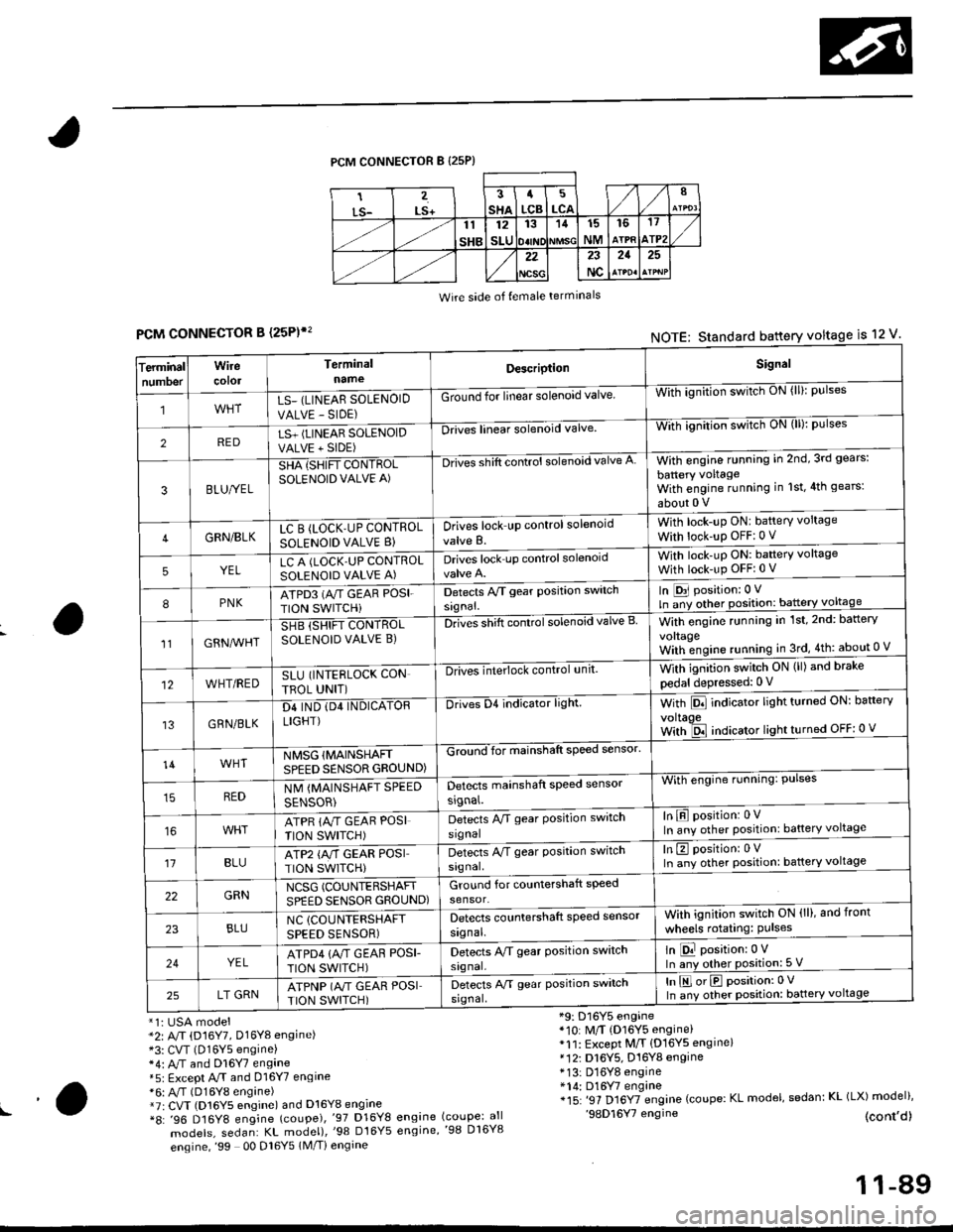
PCM CONNECTOR B {25P)
Wire side of {emale terminals
CONNECTOR B (25P)',
*1i USA model*2: A/T (D16Y7, Dl6Yg engine)*3: CVT (D16Y5 engine)*4: M and Dl6Y7 engane*5: Except A.rT and 016Y7 engine*6: A,/T (D16Y8 engine)*7r CVT (D16Y5 engine) and D16Y8 engine*8: '96 D16Y8 engine (coupe),'97 D16Y8
models, sedan: KL model),'98 Dt6Y5
engine,'99 00 Dl6Y5 1M/Ti engine
*9: D16Y5 engine*10: M/T (D16Y5 engine)*11: Except M/T {D16YS engine}*12i D16Y5, D16Y8 engine* 13: D16Y8 engine*14: D16Y7 engine*15: '97 Dl6YTengine (coupe: KL model, sedan: KL (LX) model)''98D16Y7 engine (cont,d)engine (coupe: allengine,'98 D16Y8
FCMNOTE: Standard battery voltage is 12 v'
erminalTnumoer
Wirecotol
TerminalnameDescriptionSignal
1LS_ (LINEAR SOLENOID
VALVE - SIDE)
Ground for linear solenoid valveWii-ignnion switctr oN {ll}: pulses
2REDLS+ (LINEAR SOLENOIDVALVE + SIDE)
-Drii6l linear solenoid valveWith ignilion switch uN (lll: pulses
3BLU/YEL
SHA {SHIFT CONTROLSOLENOID VALVE A)
-Drives shift control solenoid valve AWith engine running in 2nd,3rd gears:
battery voltageWith engine running in 1st,4th gears:
about 0 V
4GRN/BLKLC B (LOCK'UP CONTROL
SOLENOID VALVE B}Drives lock up control solenoid
valve B.
With lock-up ONI battery voltage
With lock-up OFF:0 v
5YELLC A (LOCK.UP CONTROLSOLENOID VALVE A)Drives lock up controlsolenoidWith lock-uP ON: baftery voltage
With lock-up OFFi 0 V
8PNKATPD3 (NT GEAR POSI.
TION SWITCHi
Detects Py'T gear Position switch
signal.
In [D31 position: 0 V
ln ;y other position: battery voltage
1lGRN^lr'HT
SHB (SHIFT CONTROLSOLENOID VALVE B)DnGs shift conttol solenoid valve BWith engine running in 1st,2nd: battery
vo|taqeWith;ngine running in 3rd,4th: about 0 V
12WHT/REDSLU (INTERLOCK CON
TBOL UNIT)
-DlivEilite'lock control,rnit.With ignition switch ON (ll) and brake
pedal depressed: 0 V
13GRN/BLK
D4 IND (D4 INDICATORLIGHT)
Drives D4 indicator light.With Pll indicator lrght turneo urr: oarterv
voltaoeWith ld indicator light turned OFF: 0 v
14WHTNMSG {MAINSHAFTSPEED SENSOR GROUND)
GZiiI'for mainshaft speed sensol
With engine running: Pulses
In E position: 0VIn any other position: battery voltage
REDNM {MAINSHAFT SPEED
SENSOR)
Detects mainshaft speed sensor
srgnal.
ATPR {M GEAR POSI
TION SWITCH)
Detects M gear Position switch
signal
't1BLUATP2 {A/T GEAR POSITION SWITCH)
Detects A/T gear Position switch
signal.
In E position: 0VIn any other position: battery voltage
22GRNNCSG (COUNTERSHAFT
SPEED SENSOR GROUND)Ground for countershaft speed
sensor.
23BLUNC (COUNTERSHAFT
SPEED SENSOR)
Detects countershaft speed sensor
signal.
Vvith ignition switch ON (ll), and front
wheels rotating: Pulses
24YELATPD4 {M GEAF POSI-
TION SWITCH)
Detects M gear Position switch
signal.
ln E position:0 VIn any other position: 5 V
25LT GRNATPNP (A"/T GEAR POSITION SWITCH)
Detects A/T gear Position switch
srgnal,
In E orE position:0 V
In any other position: battery voltage
!a
11-89
Page 359 of 2189
Troubleshooting
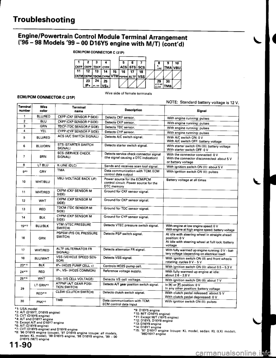
Engine/P_o_wgrtrain Control Module Terminal Arrangement('96 - 98 Models '99 - 00 Dt6y5 engine with M/T) tc'oniOi
ECM/PCM CONNECTOR C {31PI
1
CKFP
2
CXPPTDCPa
ACS
5
sTs
7
scsII
rMA
10
v8u121314t51517
ALTF
TE
vss23lP+
21252930
TMA
Wire side of female terminalsECM/PCM CONNECTOR C (31PI
NOTE: Standard baftery voltage is 12 V
'1: USA modelr2rA,.T (D16Y7, O16Y8 ensane)*3: CVT (O16Y5 engine)*4: Ay'T and O16Y7 engine'5: Excepl A./T snd Dl6Y7 engine16: Ay'T (D16Y8 ensine){7: CVT (Dl6Y5 eosine) and O16Y8 enoine"8: 96 Dl6Y8 engine (coupe),'97 D16y8 engine (coupe: atl:ed-9I t!!rnodelr,'98 D16y5 ensine,,98 D16y8 e;sine.D16Y5 lM/T) ensine
1-90
19: D16Y5 engine'10: M/T (Dl6Y5 engine)*11r Except M/T 116Y5 engine)*12: D16Y5, D16Y8 engine*13: Dl6Y8 enqine*14: O16Y7 enginei15: '-97 O16Y7 engjne (coupe: KL modet, sedan: KL (LX) modet),'98D16Y7 enqine'99 - 00
1
To.min!lnumberWiracoloaTorminalnameDo6criptlonSignal
1BLU/REDCKFP (CKF SENSOR P SIDE)Detects CKF sensor.With engine running: pulses2BLUCKPP (CKP SENSOF PSIDE)Detects CKP sensor.With engine running: pulses3GRNTDCP {TDC SENSOR PSIDE}Detects TDC sensor,With engine running: putses4YELCYPP (CYP SENSOR P SIDE)Detects CYP sensor.With engine running: pulses
5BLU/FEDACS {Tr'C SWITCH SIGNAL)Detects ,ay'C sw;tch signat.With Iy'C switch ONr 0 VWith Ay'C switch OFF: batrery vottage
6BLU/ORNSTS (STARTER SWITCHSIGNAL)Detects staner swilch signal,With staner switch ON ltlt): batery vohageWith staner switch OFF: 0 V
8RNSCS (SERVICE CHECKSIGNAL)Detects service check connector signal{the signalcausing a OTC indicationlWith the connector connected: O Vwith the connector disconnected: about 5 vor battery voltageLT 8LUK,LINE (DLC)Sends and receives scan iool signal,Wirh ignition switch ON { ): about 5 V
9+3GRYDat6 communication with TCM: ECMcontrol ctat6 outputWith ignition switch ON (tt):putses
10WHT/BLUVBU (VOLTAGE BACK UP)Power source forthe ECM/PCMcontrol circuit. Power sourc€ lortheDTC memory
Battery voltage at all times
11WHT/REDCKFM {CKF SENSOR MSIDE)Ground tor CKF sensor signal.
12CKPM (CKP SENSOR MSIDE)Ground for CKP sensor s;gnat.
REDTDCI\4 (TDC SENSOR MSIDE)Ground for TDC sensor signal.
14BLKCYPM (CKP SENSOB MSIDE}Groond for CYP sensor signal.
15."BLU/BLKVTM (VTEC PRESSUREswtTcH)Oetscts VTEC pressure switch signal.Wrth engine at low enginespeed:0 VWth engineathigh engine speed: tatteryvoltase
16GRN
PSPSW (P/S OIL PRESSUREswtTcH)Detects PSP switch signal.At idle with steering wheel in straight aheadposition:0 VAt idle with stsering wheet at fult tock batteryvoltage'17WHT/REDALTF (ALTERNATOR FRSIGNAL)Detects ahernator FR signal.With fullyw6rmed up engine running:0 V- bat-teryvohage (depending on electricat toad)18BLUI/VHTVSS {VEHICLE SPEED SEN-SOR}Oetects VSS signal.Whh ignitjon switch ON {tt) and front wheetsrotating: cycles 0 V- 5 V23+14BLKlP+ {HO2S PUtr4P CELL +}Controls HO2S pump ce .With ignition switch ON (ll): abour 0.5 - 5.3 V
24.10REDrP-, vs- {Ho2s coMt oN)Reference voltage supply.With fullywarmed up engine et idle:about2.6-2.8 V25*roVS+ (VS CELL VOLTAGE)Detects VS cell voltage.With ignition switch ON t): abour 7 V
29LT GRN*'ATPNP (Ar'T GEAR POSI,TroN swrTcH)Deteds Ay'T g6srposhion switch signat.In E orE position: O Vln any other position: battery vottage
RED{roCLSW (CLUTCH SWITCH}Detects clutch switch signal,Wilh clutch pedal released: about 5 VWith clutch pedal deDressed: O V30PNK4TMBData communication with TCM:ECM controldata inputWith ignit;on switch ON (lt):putses
Page 360 of 2189
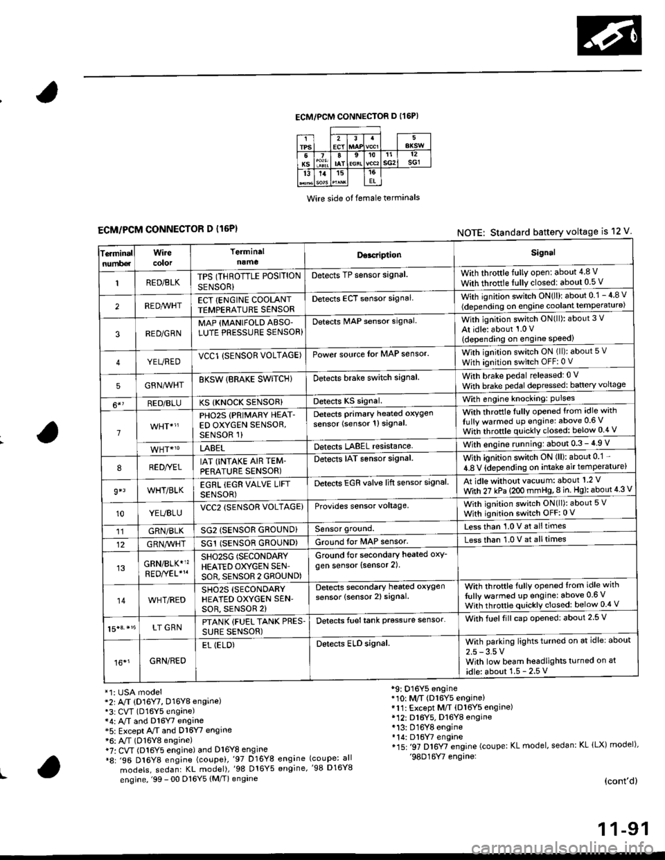
ECM/PCM CONNECTOR D I16P)
Wire side ot female terminals
ECM/PCM CONNECTOR D l16P)NOTE: Standard battery voltage is 12 V
Te.minalnumb€r
Wirecolor
Terminaln!meDor.riptionSignal
RED/BLKTPS (THROTTLE POSITION
SENSOR}
Detects TP sensor signal.With throttle fully open: about 4.8 V
With throttle fully closedl about 0.5 V
REDA/VHTECT {ENGINE COOLANTTEMPERATURE SENSORDetects ECT sensor signalWith ignition switch ON{ll): about 0.1 - 4 8 v
(depending on engine coolant lempe ratu re)
3RED/G RNMAP {MANIFOLD ABSO'LUTE PRESSURE SENSOR}Detects MAP sensor signal.With ignition switch ON(ll): about 3 V
At idle: about 1.0 V
{depending on engine speed)
YEUREDVCCl (SENSOR VOLTAGE)Power source lor MAP sensor.With ignition switch ON (ll): about 5 v
With ignition switch OFF: 0 V
5GRNMHTBKSW {BRAKE SWITCHIDetects brake switch signalWith brake pedal released: 0 v
With brake pedal depressed: baftery voltage
6*?RED/BLUKS {KNOCK SENSOR}Detects KS signal.With engine knocking: Pulses
1
PHO2S (PRIMARY HEAT-ED OXYGEN SENSOR,SENSOR 1)
Detects Primary heated oxygen
sensor (sensor 1l signal
With throttle fullv opened from idle with
Iully warmod up engine: above 0.6 V
With throttle quickly closed: below 0.4 v
LABELDetects LABEL resistanceWith engine r!nning:about 0.3 - 4.9 V
8RED//ELIAT (INTAKE AIR TEM-PERATURE SENSOR)
Detects IAT sensor signal.With ignition switch ON (ll): about 0 1 -
4.8 V {depending on intake air temperature)
9*lWHT/BLKEGRL iEGR VALVE LIFT
SENSOR)
Detects EGR valve lift sensor signalAt idle without vacuum: about'1 2 V
With 27 kPa (2OO mmHg,8 in. Hg): about 4 3 V
10YEUBLUVCC2 (SENSOR VOLTAGE)Provides sensor voltage,With ignition switch ON(ll): about 5 V
With ignition switch OFF:0 V
11GRN/BLKSG2 (SENSOR GROUND}Sensor ground.Less than 1.0 V at alltimes
12G RN,4/1r'HTSG1 (SENSOR GROUND)Ground for MAP sensor.Less than 1.0 V at alltimes
GRN/BLK*1?SHO25G (SECONDARY
HEATED OXYGEN SEN'
SOR, SENSOR 2 GROUND)
Ground for secondary heated oxy-
gen sensor (sensor 2).
14WHT/REDSH02S (SECONDARY
HEATED OXYGEN SEN'soR, sENsoR 2)
Detects secondary heated oxygen
sensor (sensor 2) signal.With throftle fully opened lrom idle with
fully warmed up engine: above 0.6 V
With throttle quickly closed: below 0.4 V
15|3. *15LT GRNPTANK {FUEL TANK PRES.
SURE SENSOR)
Detects fueltank prgssure sensor'With fuelfill caD opened: about 2.5 V
16*1GRN/RED
EL (ELD)Detects ELD signal.With parking lights turned on at idle: about
2.5 - 3.5 VWith low beam headlights turned on at
idle: about 1.5 - 2.5 V
*1: USA model*2r A/T (D16Y7, D16Y8 engine)*3: CVT (D16Y5 engane)*4: A,/T and Dl6Y7 engine*5: Except A/T and D16Y7 engine*6: A"/T (D16Y8 engine)i7: CVT (Dl6Y5 engine) and Dl6Y8 engine*8: .96 D16Y8 engine (coupei,'97 D16Y8 engine
models, sedanr KL model),'98 016Y5 engine,
engine, '99 - 00 D16Y5 (M/T) engine
*9: D16Y5 engine*10: M/T (D16Y5 engine)*11: Except M/T (Dl6Y5 engine)* 12r D16Y5. D16YB engine*13: D16Y8 engine*14: Dl6W engine*15: '97 D16Y7 engine (coupe: KL model, sedan: KL lLX) model),'98D16Y7 engine:(coupe: all'98 D16Y8
(cont'd)
1 1-91
Page 361 of 2189

Troubleshooting
Engine/P_o,wertrain Control Module Terminal Arrangement('99 - 00 Models except Dl6Y5 engine with M/Tl
ECM/PCM CONNECTOR A (32P)Wire side ot temale terminalsNOTE:Standard battery voltage is l2 V
ECM/PCM CONNECTOR A I32PI
Sign!l
3BLU2WSS (EVAP 8YPAsS SOLENOIDDrives EVAP bypass solenoid vatve,With gn'tion swnch ON (lll banery votlage
LT GRN/I/VIITVSV {EVAP CONTNOL CANISTERVENTSHUTVALVE]Drives EVAP controt ca n isrer v€nt shutWilh ignilion switch ON {tl): b€ttery vottage
8LU/GNNC8S (CRUISE CONTSOL SIGOown shift signal inpot lrom c.uise conrrolWhen crurss control is used:purses
68ED/YELPCS {EVAP PURGE CONTROLSOTENOIOVALVE)Drives EVAP purge conrrol sotenoid vatve.With engine running, engine cootant, betow r54.F (6a,C):
With engine.unning, €ngine coolant, abov€ 154.F(68'C): duty conlrolled
YELATPD {AT GEAR POSITIONSWITCH)ootects A/T gear posnion swilch s,gnar.In otherthan @ posilion: Apprcx. 5 V
8BLK,IflHTSO2SHTC (SECONDARY HEATED OXYGEN SENSOS HEATEFCONTFOL)
Drives sscondary h€ared oxygen senso.Wilh isn,rion swirch ON (ll):banery votraseWith lully warm6d dp€ngire runn'ng:dury controled
LT GRNATPNP (AT GEAF POSITIONSWITCH)oereds A/T 9€a r position switch signat.In Parr or neulrsl:0 VIn anyother position approx.5 v
t088NSCS (SERVICE CHECK SIGNAL)Oetects ssruice check connecror signal(the signalcausing a OTC indication)with rh€ t6rminal connected: 0 vWith the rerm ina I disconneded: abour 5 V of ban€ry
GNN/BIKD4IND (D4INDICATON]Drives Oa indicaio. lighr.With D4 indicator lightturned ON: O VWith D4 indicator lightturned OFF: battery vo ttageG8N/YETFTF (FUEL PUI\,4P SELAY)Orivos tuel pump relay,0V for two s€conds lfrer turnrng rgnilior swtcn ON(ll), then batt€ry voltage11BTI(REDACC (Al/C CTUTCH SELAY)Drives A./C clutch reray.With compressor ON:O VWilh comp.ssor OFF; battery vottage18GFN/OFNMI! (A,IAIFUNCTION INDICA.TOF LIGHT)With MlLturned ON:0 VWith l\,llL tornod OFF|batrery votrsge198tuNEP (ENGINE SPEED PUTSEIOulputs6ngine speed pulse,Wilh engin6.unning: putses
20GFNFANC {SADIATOR FAN CONTnoL)Orives radiarortan relay.Wirh r.distor t6n running:OVWith radiatortan stopped: banery vottage21ELUA/ELK LINESends and r€ceives s.an lool signal.With ignition switch ON (ll):p!ts€s
22'lBLUATP L {AT GEAS POSITIONswtTcH)Oelocis A"/T gear posirion switch siSnat.In othfflhan E position: Apprcx. 5 V
23SHO25 (SECONOARY HEATEDOXYCEN SENSOR, SENSOF 2)Detects secondsry hoar€d oxygen sensorWith lhronle f! lly or'6ned from idte with fu ywarmod up engine: above 0.6 vWiih th.onl6 quickb, closd:below 0,4 V24STS ISTAFTEN SWITCH SIGDebcrs staner switch signat.Wirh srarterswitch ON (tttJ: batteryvottogeWith sraftsr cwirch OFF:0 V26GFNPSPSW iPlS PNESSURESWITCII SIGNAL)Derecrs PSP switch signat.Atidle with steoring wheolin srraightahead position: O VAt idl6with steering wheetal fult lock: barery vo ttags27BLU/REOACS (AJC SWITCH SIGNALJOer*ts ,ay'C swirch signat.Wiih ty'C switch ON;0VWilh Ay'C switch OFF|aboor 5VWHT/REDSLU iINTERLOCK CONTROIUNIT)Drivos interloct control unit.With ignltion switch ON (ll)and brake pedaldepresed: batlory volrage29LT GRNPTANK (FUEL TANK PFESSUEESENSOR)Oer6ds lu€l tank pr€ssura sonsor signat.Wilh ig.rrrd swirch ON rttr and fuetti
cap ooen6d.
30GRN/FEOEr (ELOIWith parking lighlsrurned on ar idteiaboui 2.5- 3.S VWirh low beam he€dlig hts turnqd on ai idts: aboul 1.52.5 V32GRN/'WHTAKSW (BFAKE SWITCH)Detets brak€ swrtch signEt,With brake pedal r6l€ased:0 VWhh brake pedaldepres*d: battery voltEse'1:A./T (D16Y7, D16Y8 engine)*2: rvt/T13: CVT (D16Y5 engine)
11-92