2000 HONDA CIVIC headlight
[x] Cancel search: headlightPage 478 of 2189

tAlternator (ALT) FR Signal ('99 - 00 Models except Dl6Y5 engine with M/T)
This signals the ECM/PCM when the Alternator {ALT) is chargingECM/PCM CONNECTORS
Wire side of female terminals
ECM/PCM CONNECTOR C (31P}
lt
lP
ALT CONNECTORS IClO4I
JUMPER
JUMpER WlnE
WIRE
Wire side of female termlnals
ECM/PCM CONNECTOR C (31PI
3P*NO
Check lor an op€n in the wire (ALT
F line,:1. Turn the agnition switch OFF
2. Disconnect the negative bat-
tery cable {rom the battery.
3. Disconnect the ECM/PCM con'
nector C (31P).
4. Disconnect the 4P (3P)* con'
nector from the ALT.
5. Connect the ALT 4P (3P)* con-
nector terminal No 4 (No. 1)*
to bodY ground with a iumper
6. Check lor continuity between
body ground and ECM/PCM
connector terminal C5
--?--1l2l|�#i3l.l
otriJrwxrr (V)
neor Y
lnsoeclion oI ALT FB Signal.
Check {or a short in the wire {ALT
F line):1. Disconnect the 4P (3P)+ con
nector from the ALT
2. Turn the ignition switch ON (ll)
3. Measurc voltage between EcM/
PCM connector terminals C5
and 820.Check tor a short in the wirc (ALt
F line):1. Turn the ignition switch OFF
2. Disconnect the negative bat_
tery cable from the baRery'
3. Disconnect the ECM/PCM con'
nector C (31P).
4. Check for continuity between
body ground and ECM/PCM
connector terminal C5
ls there aPProx. 5 V?
Check the operation otthe ALT:
1. Turn the ignition switch OFF.
2- Reconnect the ALT 4P (3P)*
connector to the ALT
3. Start the engine. Hold the
engine at 3,000 rpm wrth no
load {in Park or neutrali until
the radiator fan comes on,
then let it idle.
4- Measure voltage between ECM/
PCM connector terminals C5
and 820.
Repair short in the wire between
the EcM/PCM {C5l and the ALT.
Substitute a known-good ECM/
PCM and rechock. lf P.esc.ibedvoltage is now availabl€, ieplace
tho original ECM/PCM
Does the voltage decrease when
headlights and rear delogger are
turned on?
ALT FF signal is OK.
Repair oPen wire betwoen t|lo
ECM,/PCM {C5) and the ALT.
ALT F (WHT/RED)
Wire side of temale terminals
*: Canada model
Wire side of female termrnals
Page 489 of 2189

ldle Control System
ldle Speed Setting
Inspection/Adiustmenl
'96, '97 Dl6Y5. '96 - 00 Dl5Y8 sngine with M/T
NOTE:
. Before setting the idle speed, check the following
items:- The MIL has not been reported on.- lgnition timing- Spark plugs- Air cleaner- PCV system
o (Canada) Pull the parking brake lever up. Start the
engine, then check that the headlights are off.
1. Start the engine. Hold the engine at 3.000 rpm withno load (taansmission in neutral) until the radiatorfan comes on, then let it idle.
2. Connect a tachometer.
3. Disconnect the IAC valve connector.
4.lf the engine stalls, restart the engine with the accel-
erator pedal slightly depressed. Stabilize the rpm at1,000, then slowly release the pedal until the engineidles.
Check idling in no-load conditionsr headlights. blowerfan. rear defogger, radiator fan, and air conditioner
are not operating.
ldle spsed should be:
450 1 50 rpm
11-220
Adjust the idle speed, if necessary, by removing thecap and turning the idle adjusting screw.
NOTE; After adjusting the idle speed in this step,recheck the ignition timing (see section 23).
lf it is out of spec, go back to step 4.
IDLE
6. Turn the ignition switch OFF.
7. Reconnect the 2P connector on the IAC valve, then
do the ECM reset procedure.
8. Restart and idle the engine with no-load conditionsfor one minute, then check the idle speed.
NOTE: (Canada) Pull the parking brake lever up.Start the engine, then check that the headlights areoff.
ldle sp€sd should b€:
670 i 50 rpm IUSA)750 t 50 rpm {Canada}
9. ldle the engine tor one minute with headlights {Low)ON. and check the idle speed.
ldle speed should be:
750 :r 50 rpm
10. Turn the headlights off. ldle the engine for oneminute with heater fan switch at Hl and air conditioneron, then check the idle speed.
ldle speed should be:
810150 rpm
NOTE: lf the idle speed is not within specification,see Symptom Chan on page 11-84.
Page 491 of 2189
ldle Control System
ldle Speed Setting (cont'dl
Inspeqtion/Adiustment
38 D16Y5 engine whh M/T,'99 - 00 81642 engine
NOTE: Before setting the idle speed, check the follow-ing items;- The MIL has not been reported on.- lgnition timing- Spark plugs- Air cleaner- PCV system
'1. Start the engine. Hold the engine at 3,000 rpm withno load (transmission in neutral) until the radiatorfan comes on, then let it idle.
Connect a tachometer.
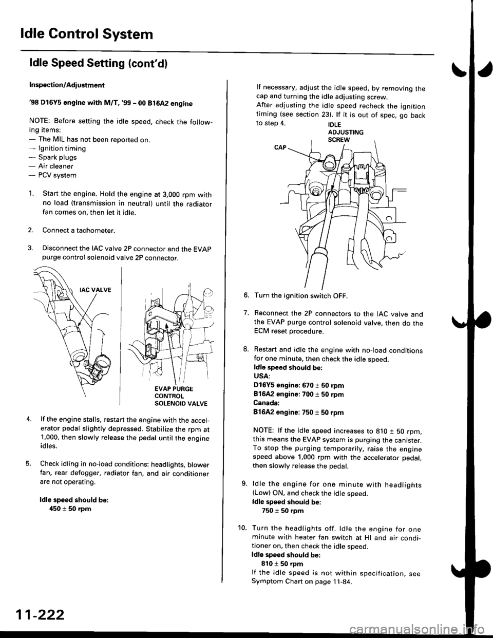
Disconnect the IAC valve 2P connector and the EVAPpurge controlsolenoid valve 2P connector.
EVAP PURGECONTROLSOLENOID VALVE
lf the engine stalls, restart the engine with the accel-erator pedal slightly depressed. Stabilize the rpm at1.000, then slowly release the pedal until the engineidles.
Check idling in no-load conditions: headlights, blowerfan, rear defogger, radiator fan, and air conditionerare not operating.
ldl€ speed should be:
450 i 50 rpm
11-222
lf necessary, adjust the idle speed, by removrng lnecap and turning the idle adjusting screw.After adjusting the idle speed recheck the ignitlontiming (see section 23). lf it is out of spec, go backto step 4. |DLE
6. Turn the ignition switch OFF.
7. Reconnect the 2P connectors to the IAC valve andthe EVAP purge control solenoid valve, then do theECM reset procedure.
8. Restart and idle the engine with no-load conditionsfor one minute, then check the idle sDeed.ldle speed should bo:
USA:
D16Y5 engine: 670 i 50 rpm
81642 engine: 700 i 50 rpm
Canada:
81642 engine: 750 t 50 rpm
NOTE: lf the idle speed increases to 8lO t 50 rpm,this means the EVAP system is purging the canister.To stop the purging temporarily, raise the enginespeed above 1,000 rpm with the accelerator pedal,
then slowly release the pedal.
9. ldle the engine for one minute with headlights(Low) ON. and check the idle speed.
ldle speed should be:
750 i 50 rpm
10. Turn the headlights off. ldle the engine for oneminute with heater fan switch at Hl and air condi-tioner on, then check the idle soeed.ldls speed should be:
810 t 50 rpm
lf the idle speed is not within specification, seeSymptom Chart on page 11-84.
Page 521 of 2189
Emission Gontrol System
System Description
The emission control system includes a Three Way Cata-lytic Convener (TWC), Exhaust Gas Recirculation (EGR)
system,. Positive Crankcase Ventilation (pCV) system andEvaporative Emission (EVAP) Control system. The emis-sion control system is designed to meet federal and stateemission standards.*: D16Y5 engine
Tailpipe Emission
Inspestion
@@ Do not smoke during ihis procedure. Keepany open flame away from your work area.
1. Start the engine. Hold the engine at 3,000 rpm withno load (in Park or neutral) until the radiator fancomes on. then let it idle.
2. Connect a tachometer.
Check and, if necessary, adjust the idle speed (see
page 11-220 - 223).
Warm up and calibrate the CO meter according to themeter manufacturer's instructions.
Check idle CO with the headlights, heater blower,rear window defogger, cooling fan, and air condition-er off.
NOTE: (Canada) Pull the parking brake lever up.Start the engine, then check that the headlights areoff.
CO mete. should indicate 0.1% maximum.
NOTE: '98 Dl6Y5 engine - lf the idle speed incress-es to 8101 50 rpm, this means the EVAp system ispurging the canister. To stop the purging temporari-ly. raise the engine speed above 1,000 rpm with theaccelerator pedal, then slowly release the pedal.
11-252
eFORWARD -
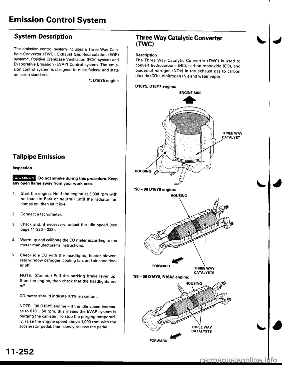
Three Way Catalytic Converter
(TWCI
Doscription
The Three Way Catalytic Converter (TWC) is used toconven hydrocarbons (HC), carbon monoxide (CO), andoxides of nitrogen (NOx) in the exhaust gas to carbondioxide (COr), dinitrogen (N,) and water vapor.
D15Y5, D16
, engine:
'99 - 00 D16Y8, 81642 engine:
ENGINE SIDE
t
Page 1498 of 2189
Connector ldentification and WireHarness Routing
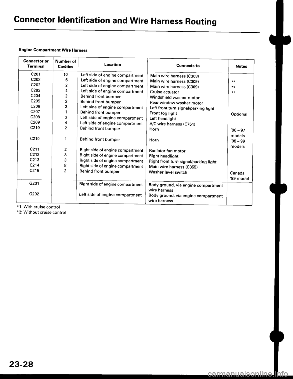
Engine Compartment Wire Harness
conneqtor of
Terminal
Number of
CavitiesLocationConnects toNotes
c201
c202
c202
c203
c204
c205
c206
c207
c208
c209
c210
c210
c211
c212
c213
c214
c215
10
6
2
2
2
1
3
2
1
2
8
Left side of engine companment
Left side of engine companment
Left side of engine companment
Left side of engine compartment
Behind front bumper
Behind front bumper
Left side of engine compartment
Behind front bumper
Left side of engine compartment
Left side of engine companment
Behind front bumper
Behind front bumper
Right side of engine compartment
Right side of engine compartment
Right side of engine compartment
Right side of engine compartment
Behind front bumper
Main wire harness (C308)
Main wire harness (C309)
Main wire harness {C309)Cruise actuator
Windshield washer motor
Rear window washer motor
Left front turn signal/parking lightFront fog light
Left headlight
Ay'C wire harness 1C751)Horn
HOrn
Radiator fan motor
Right headlight
Right front turn signal/parking lightMain wire harness (C355)
Washer level switch
Optional
'96 - 97
models'98 - 99
models
Canada'99 model
G201
G202
Right side of engine compartment
Left side of engine compartment
Body ground, via engine compartmentwire harness
Body ground, via engine compartmentwrre harness*1r With cruise control*2: Without cruise control
23-2A
Page 1533 of 2189
(l'-
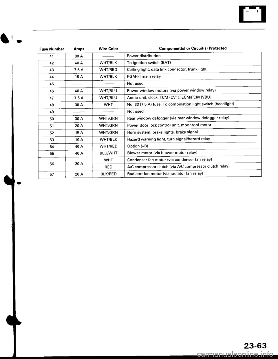
Fuse NumberAmpswire ColorComponent(s) or Circuitlsl Protect€d
4180APower distribution
4240AWHT/BLKTo ignition switch (BAT)
437.5 AWHT/REDCeiling light, data link connector, trunk light
4415 AWHT/BLKPGM-Fl main relay
Not used
4640AWHT/BLUPower window motors (via power window relay)
477.5 AWHT/BLUAudio unit, clock, TCM (CVT), ECM/PCM (VBU)
4830AWHTNo.33 (7.5 A) fuse, To combination light switch (headlight)
49Not used
5030AWHT/GRNRear window defogger (via rear window defogger relay)
cl20AWHT/GRNPower door lock control unit, moonroof motor
15 AWHT/GRNHorn system, brake lights, brake signal
10 AWHT/BLKHazard warning light, turn signal/hazard rclay
54404WHT/REDOption {+B)
5540ABLU,A/VHTBlower motor (via blower motor relay)
204WHTCondenser fan motor (via condenser fan relay)
REDl'lc compressor clutch (via IVC compressor clutch relay)
204BLVBEDRadiator fan motor (via radiator fan relay)
23-6
Page 1535 of 2189
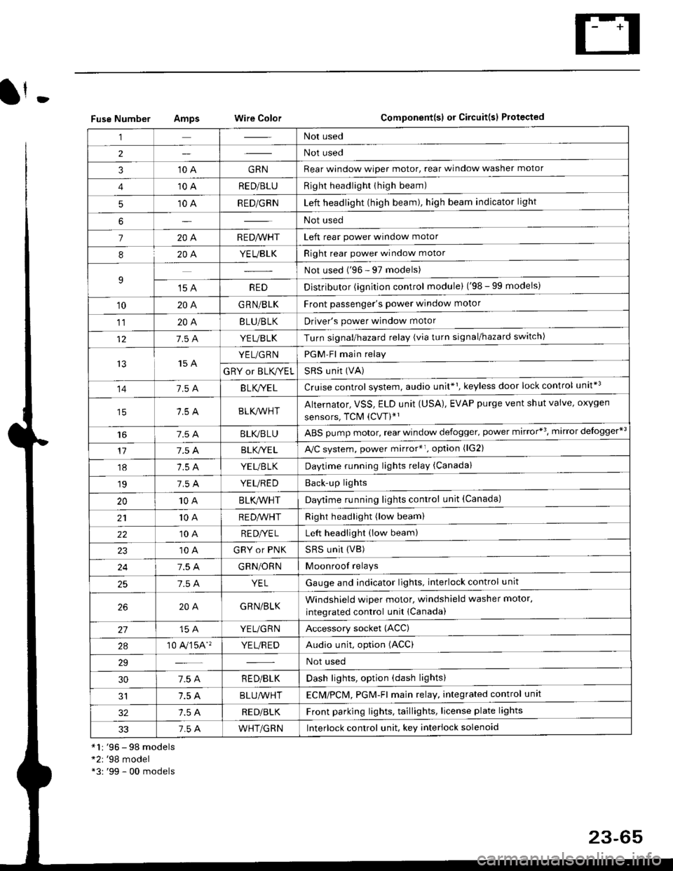
lr-
Fuse NumberAmpswire ColorComponent{sl or Circuit(sl Protected
*1r '96 - 98 models*2r '98 model*3: '99 - 00 models
,lNot used
2Not used
310 AGRNRear window wioer motor, rear window washer motor
410 ARED/BLURight headlighr thigh beam)
510 ARED/GRNLeft headlight (high beam), high beam indicator light
6Not used
7204R E D/VVHTLeft rear power window motor
820A.YEUBLKRight rear power window motor
9Not used ('96 - 97 models)
't5 AREDDistributor (ignition control module) ('98 - 99 models)
10204G RN/BLKFront passenger's power window motor
1120ABLU/BLKDriver's power window motor
127.5 AYEUBLKTurn signal/hazard relay (via turn signal/hazard switch)
t515 AYEL/GRNPGM-Fl main relay
GRY or BLK,^/ELSRS u nit (VA)
141.54B LK/YE LCruise control system, audio unit*1, keyless door lock control unit*3
BLK/lr'r'HTAlternator, VSS, ELD unit (USA), EVAP purge vent shut valve, oxygen
sensors, TCM (CVT)*'
t6BLI(,/BLUABS pump motor, rear window defogger. power mirror*3, mirror delogger*3
177.5 ABLK,/YE LA,/C system, power mirror*r. option (lG2)
18YEUBTKDaytime running lights relay (Canada)
197.5 AYEUREDBack'up lights
2010ABLK/VVHTDaytime running lights control unit (Canada)
2110 AREDA/VHTRight headlight (low beam)
2210 ARE DI/E LLeft headlight (low beam)
10 AGRY or PNKSRS UNit (VB)
247.5 AGRN/ORNMoonroof relays
257.5 AYELGauge and indicator lights. interlock control unit
204GRN/BLKWindshield wiper motor, windshield washer motor,
integrated control unit {Canada)
15 AYEL/GRNAccessory socket (ACC)
2a10 A,/'�]5A''YE L/R EDAudio unit, option (ACC)
29Not used
307.5 AR ED/BLKDash lights, option (dash lights)
1.5 ABLUA/VHTECM/PCl\4, PGM-Fl majn relay, integrated control unit
RED/BLKFront parking lights, taillights, license plate lights
337.5 AWHT/GRNlnterlock control unit. key interlock solenoid
23-65
Page 1544 of 2189
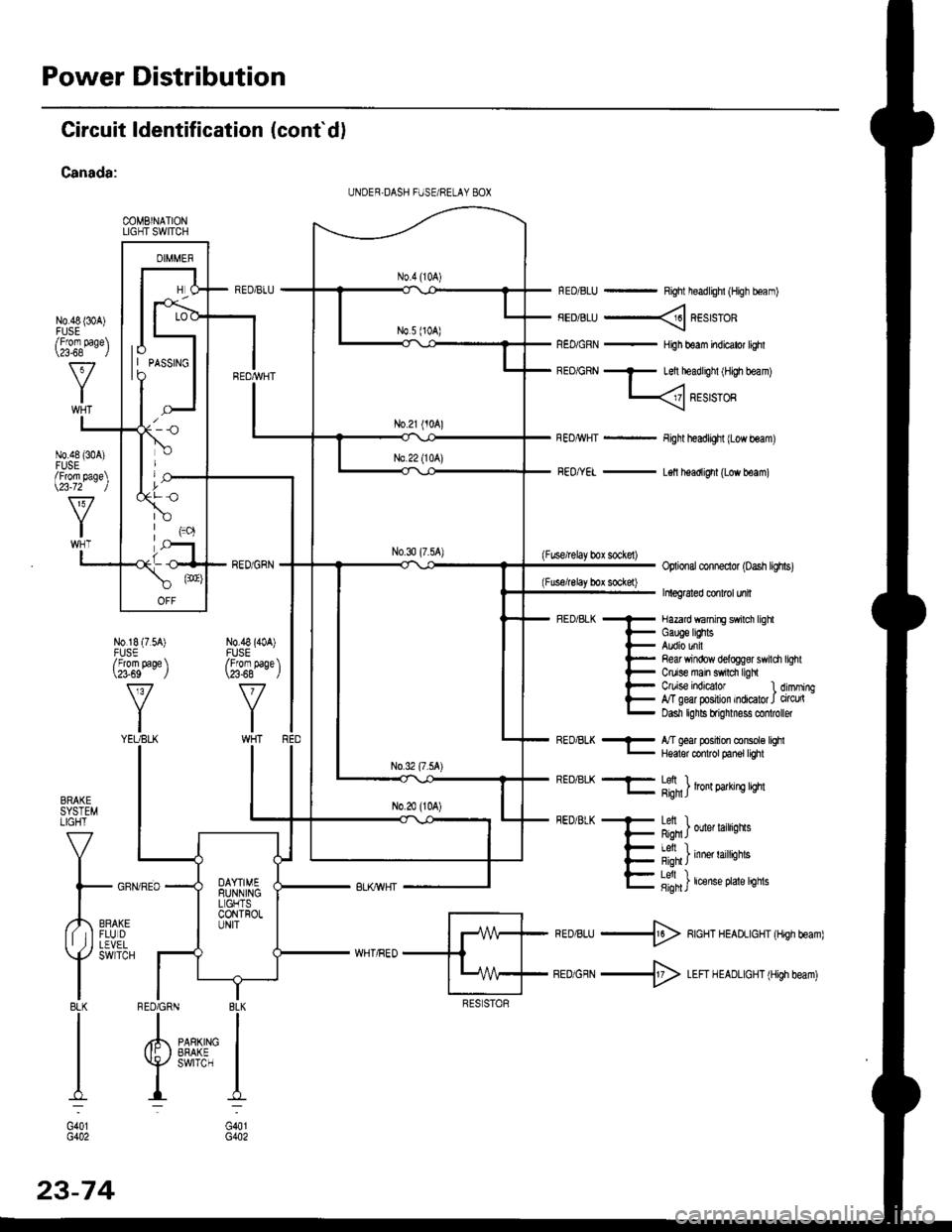
Power Distribution
Circuit ldentification (cont'd)
Canada:
COMBINATIONLIGHT SWITCH
N0.48 {30A)
RED/BLU - Right headlighl (High boam)
FEDiBLU ----< REstsTOR
REo/GRN - HiJh beam indicator lighl
BEo/GRN - Left headlighl iH,gh beam)
L
FEo/YEL - L€ll headlight (Low beam)
(Fuse/lelay box sockel)Optional conneclor (oash lighs)
Inleg6led conlrcl unil
- Hazard wanirE swilch lighl
i- Gauge lEhts
l- Audio unil
l- Re& Yrindow delogg8r swili
t- Ctuise main swrdr ligh
l- C/uise indEator l
E g"ffiry:'l,:1':::1
Refi window delog$r swildr light
Ctuise indicalor 1 dimming,T geal posilion indicator J circu(Dasn lghls brignmess co oller
BRAKESYSTEMLIGHT
V
I
l- GFf
,,4,,0*,lf tIFLUDII ,j I LEVEL
Y
SWTCH
I8LKI
I
I
I:
G401G402
REo/BLK - l/T ged position console lqhl- Hqalor codrot panel tighl
REO/BLK -F- Lefi ) .l- g;n1J lron 9arrn! qm
FEDiBLK + Letl I
F Rqn J ouer larrqns
- I Al, I
{- i'-;*; inne' raittiotts
E fifi]t'"nt"o't't'sn"
*ro,rru -$ RcHT HEADLIGHT (Hrgh beam)
BEDiGRN -+ LEFI H EADLIGHT (High beam)
I BLK
IIPARKING IEFAKE IswrrcH I
I:
G401G402
UNDER,DASH FUSE/RELAY 8OX
lo| | PASSTNGto
/Fforn page\\a-68 l
N0.48 {304)FUSE/From page\\23-72 )
N0.18 (7.54)FUSE/From page \\?3-69 J
v
YIYEUBLK
N0.48 (40A)FUSE/From paqe \\23-68 - ,/
RED6RN
23-74