Page 1177 of 2189

Brake Booster InsPection
FunctionalTest
1. With the engine stopped, depress the brake pedal
several times to deplete the vacuum reservoir, then
depress the pedal hard and hold it for 15 seconds lf
the pedal sinks' either the master cYlinder is
bypassing internally, or the brake system (master
cylinder. lines. modulator, proportioning control
valve, or caliPer) is ieaking.
2. Start the engine with the pedal depressed lf the
pedal sinks slightly, the vacuum booster is operating
normally. lf the pedal height does not vary, the
booster or check valve is faultY.
3. With the engine running. depress the brake pedal
lightly. Apply just enough pressure to hold back
automatic transmission creep. lf the brake pedal
sinks more than 25 mm (1.0 in.) in three minutes,
the master cvlinder is faulty. A slight change in
pedal height when the A'lC compressor cycles on
and off if normal. (The A/C compressor load
changes the vacuum available to the booster')
Leak Test
1. Depress the brake pedal with the engine running.
then stop the engine. lf the pedal height does not
vary while depressed for 30 seconds, the vacuum
booster is OK. lf the pedal rises. the booster is
faulty.
2, With the engine stopped, depress the brake pedal
several times using normal pressure When the
Dedal is first depressed, it should be low On con-
secutive applications, the pedal height should grad-
uallv rise. lf the pedal position does not vary, checK
the booster check valve.
l./
19-23
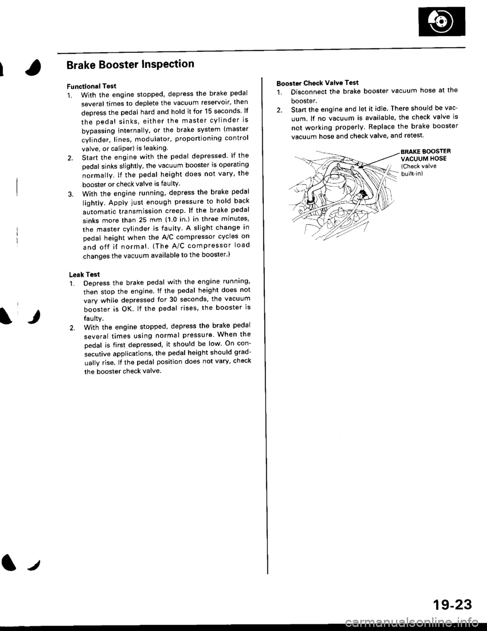
Booster Check Valve Test
1. Disconnect the brake booster vacuum hose at the
booster.
2. Stan the engine and let it idle. There should be vac-
uum. lf no vacuum is available, the check valve is
not working properly. Replace the brake booster
vacuum hose and check valve, and retest.
BRAKE BOOSTERVACUUM HOSE(Check valve
built-in)
Page 1202 of 2189
L
Wheel Soeed and Modulator Contlo
t
OUTLETVALVE ON
OFF
INLETVALVE ON
OFF
t\,40ToR
ON
OFF
when the wheel speed drops sharply below the vehicle speed, the inlet valve closes to retain the caliper fluid pressure
When the wheel speed drops further, the outlet valve opens momentarily to reduce the caliper fluid pressure. The pump
motor starts at this time.
As the wheel speed is restored, the inlet valve opens momentarily to increase the caliper fluid pressure.
Wheel SensoJ
The wheel sensors are the magnetic contactless type
As the gear pulser teeth rotate past the wheel sensor's magnetic coil, AC current is generated The AC frequency changes
in accordance with the wheel speed. The ABS control unit detects the wheel sensor signal frequency and thereby detects
the wheel speed.
There are four wheel sensors, one for each wheel
The gear pulser has 50 teeth.
EEL SPEED
at LOW SPEEDgl
=o
GEAR PULSEBWHEEL SENSOBat HIGH SPEED
/
19-49
Page 1393 of 2189

Troubleshooting -'99 - 00 Models
Symptom
Mode control motor does not run, or one or more modes are inoperat've'
Recirculation control door does not change between Fresh and Recirculate'
Blower motor only runs on high speed position; it does not run in any other speed positions
Blower motor does not run at all.
Both heater and Ay'C do not work
See pags
a1_tq
21-21
21-29
21-31
21 35
Symptom Chart
For electrical malfunctions which are indicated by the self-diagnostic system, refer to self-diagnosis function (see next
page).
Note these items before troubleshooting a symptom'
. Check the engine coolant level, and allow the engine to warm up before troubleshooting'
. Any abnormality must be corrected before continuing the test
.Becauseoftheprec|semeasurementsneeded,UseadigitaImu|timeterwithanoutputoflmAor|essatthe20ko
range when testing
. Before performing any troubleshooting procedures check:
- Fuses No. 41 115 Al, No 55 (40 A)]n the under-hood fuse/relay box' and No 17 (7 5 A) in the under-dash fuse/relav
box- Grounds No. G401, G402
- Cleanliness and tightness of all connectors
21-19
Page 1429 of 2189

Description
Outline
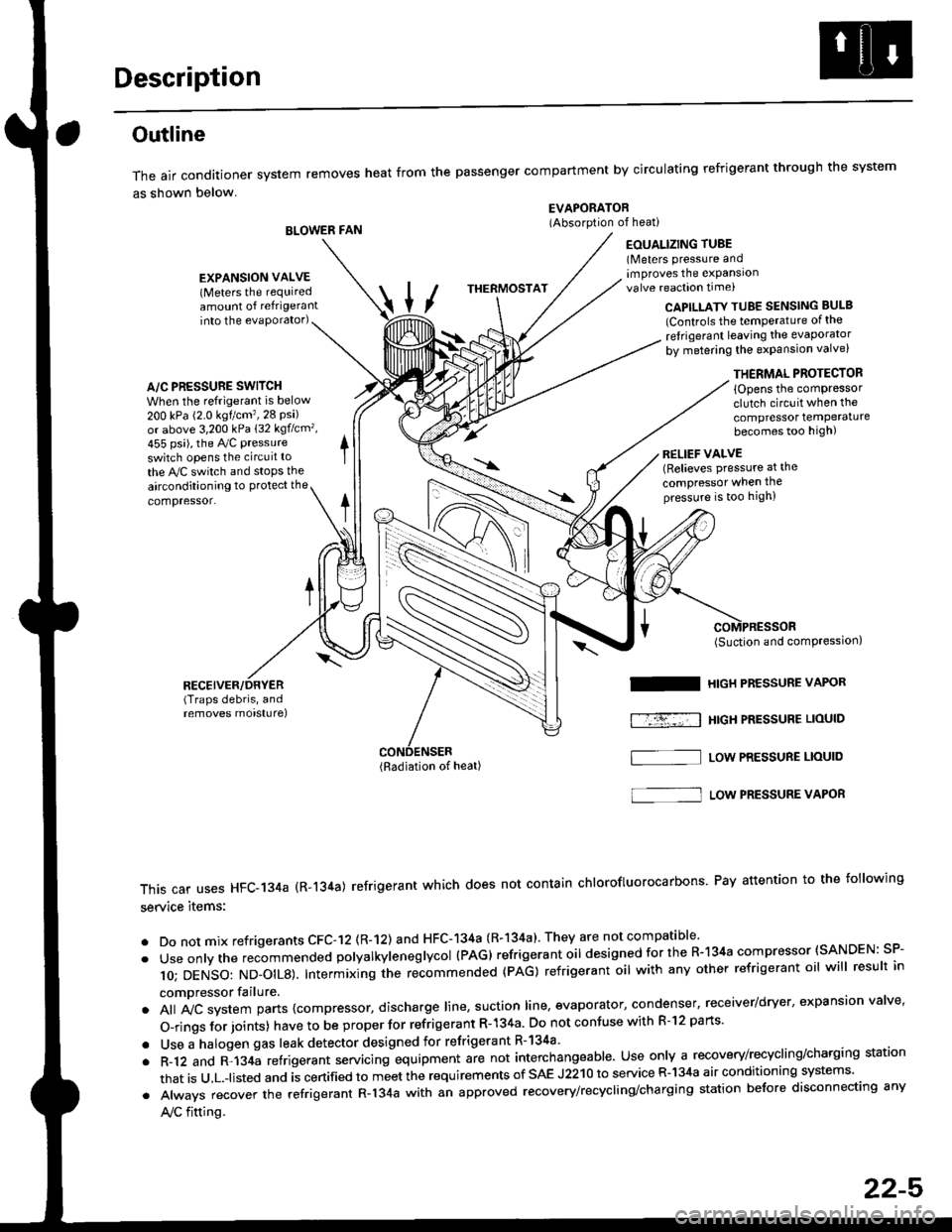
The air conditioner system removes heat from the passenger compartment by circulating refrigerant through the system
as shown below.
BLOWER FAN
EVAPORATOR(Absorption of heati
EOUALIZING TUBE(Meters pressure andimproves the expansionvalve reaction time)
into the evaporator)CAPILLATY TUBE SENSING BULB
lControls the temPerature of the
ref rigerant leaving the evaporator
by metering the expansion valve)
/\
THERMOSTAT
A/C PRESSURE SWITCH
When the refrigerant is below
200 kPa (2.0 kgtcm'�,28 Psi)or above 3,200 kPa 132 kgflcm',
455 psi), the Ay'C pressure
switch opens the circuit to
the A,/C switch and stops the
EXPANSION VALVE(Meters the requiredamount of refrigerant
airconditioning to Protect the
compressor.
RECEIVER/DRYER(Traps debris, andremoves morsturel
THERMAL PROTECTOR
{Opens the comPressorclutch circuit when the
compressor temPeraturebecomes too high)
RELIEF VALVE(Relieves pressure at the
compressor when thepressure is too high)
(Radiation of heat)
I
f-r-�-; I
(Suction and comPression,
HIGH PRESSURE VAPOR
HtGH PRESSUBE LIOUID
LOW PRESSURE LIOUID
This car uses HFC-134a (R-134a) refrigerant which does not contain chlorofluorocarbons Pay attention to the following
service items:
. Do not mix refrigerants CFC-12 (R-12) and HFC-134a (R-134a)' They are not compatible'
. Useonlythe recommended polyalkyieneglycol (PAG) refrigerant oil designedforthe R-134a compressor (SANDEN: SP-
10; DENSO: ND_OIL8). Intermixing ihe re-commended (pAG) refrigerant oil with any other refrigerant oil will result in
compressor failure.
. All A,,ic system parts {compressor, discharge line, suction line, evaporator, condenser, receiver/dryer, expansion valve'
O-rings for joints) have to be proper for refrigerant R- 134a Do not confuse with R-l2 parts'
. Use a halogen gas leak detector designed for refrigerant R-134a
. R-12 and R-134a refrigerant servacing equipment are not interchangeable. Use only a recovery/recycling/charging station
that is u,L.-listed and is certified to meet the requirements of sAE J2210 to service R-134a air conditioning systems'
. Always recover the refrigerant R-134a with an approved recovery/recycling/charging station before disconnecting any
A,/C fitting.
S]
22-5
Page 2065 of 2189

Security System Alarm Does Not Trigger
When The System ls Armed And The
Trunk Or A Door ls Opened
Security System Does Not "Be€p" 3 Times
When The System is Armed With The Trunk
Or A Door Open (HX, LX, EX, Dx-V SD
1. Place the ceiling light in the center position, then
open and close the doors one at a time. Do all
the doors operate the ceiling light properly?
Yes - Go to the next steo.
No - Repair the ceiling light circuit.
With the ignition switch in the ON (ll) position,
does the trunk open indicator in the gauge
assembly come on with the trunk open?
Yes - Go to the next step.
No - Faulty trunk latch switch or an open in the
BLU/BLK wire.
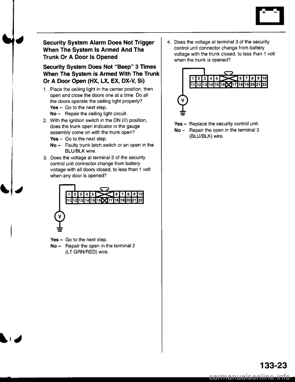
Does the voltage at terminal 2 of the security
control unit connector change trom battery
voltage with all doors closed, to less than I volt
when any door is opened?
Yes - Go to the next step.
No - Repair the open in the terminal 2
(LT GRN/RED) wire.
4. Does the voltage at terminal 3 of the security
control unit connector change from battery
voltage with the trunk closed, to less than 1 volt
when the trunk is opened?
Yes - Replace the security control unit.
No - ReDair the oDen in the terminal 3
(BLU/BLK) wire.
133-23