Page 824 of 2189
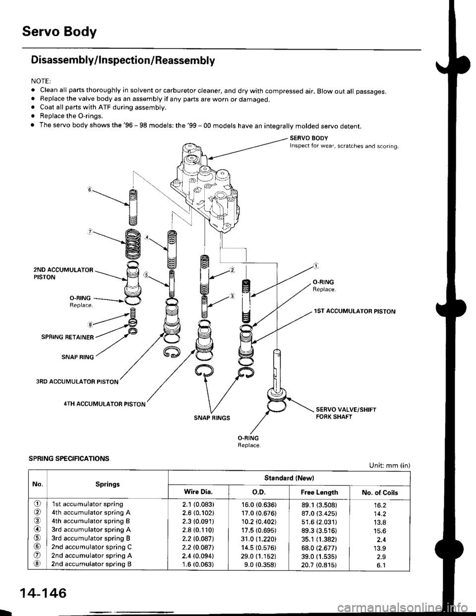
Servo Body
Disassembly/lnspection/Reassembly
NOTEI
. clean all parts thoroughly in solvent or carburetor cleaner, and dry with compressed air. Blow out all passages.. Replace the valve body as an assembly if any parts are worn or damaged.. Coat all parts with ATF during assembly.
. Replace the O-rings.
. The servo body shows the '96 - 98 models: the '99 - 00 models have an integrally molded servo detent.
SERVO BODYInspect for wear, scratches and scoring.
,______.- g
1l
v
"-------'g
ZruO lCCUr,irUr-nrOn ---rrr___-p
n\='l
3,ii11---------*5
^rrr4
I
O.RINGReplace.
3RO ACCUMULATOR PISTON
4TH ACCUMULATOR PISTON
SPRING SPECIFICATIONS
SNAP RINGS
1ST ACCUMULATOR PISTON
Unit: mm (in)
No.SpringsStandard {New)
Wire Dia.o.D.Free LengthNo. of Coils
o(a
@)
o
@
'I st accumulator spring
4th accumulator spring A
4th accumulator spring B
3rd accumulator spring A
3rd accumulator spring B
2nd accumulator spring C
2nd accumulator spring A
2nd accumulator spring B
2.1 (0.083)
2.6 (0.102)
2.3 (0.091)
2.8 (0.110)
2.210.0871
2.2 t0.0a7l
2.4 (0.094)'1.6 (0.063)
16.0 (0.636)
17.0 (0.676)
10.2lo.402J
17.5 (0.695)
31.0 11.220)
14.5 (0.576)
29.0 (1.152)
9.0 (0.358)
89.1 (3.s08)
87.0 (3.425)
51.6 (2.031)
89.3 (3.516)
35.1 (1.382)
68.012.677)
39.0 (1.535)
20.7 (0.815)
14.2
13.8
'13.9
L
14-146
Page 835 of 2189
SNAP RING
2NDi4TH CLUTCH
SNAP RING
SPRING RETAINER
RETURN SPRING
DISC SPRING
CHECK VALVE
O.RINGSReplace.4TH CLUTCH DRUM
CLUTCH PISTON
CLUTCH PLATESStandardthickness: O-RINGS2.0 mm {0.079 in) Replace.
SNAP RING
14-157
Page 840 of 2189
Clutch
Reassembly
NOTE:
. Clean all parts thoroughly in solvent or carburetor
a
cleaner, and dry them with compressed air.
Blow out all passages.
Lubricate all parts with ATF before reassembly.
Inspect the check valve; if it's loose, replace the pis-
to n.
1.
CHECK VALVE
2. Install new O-rings on the clutch piston.
O RINGS
PISTON
-
14-162
3. Install the piston in the clutch drum, Apply pressure
and rotate to ensure proper seating,
NOTE: Lubricate the piston O-ring with ATF beforeinstalling.
CAUTION: Do not pinch the O-ring by insta ing thepiston with too much force.
CLUTCII DRUM
Install the return spring and spring retainer, andposition the snap ring on the retainer.
CLUTCI{ DRUM
Page 996 of 2189
l.
1.
2.
Remove the end cover {three 6 mm bolts, eleven 8
mm bolts).
Remove the manualvalve body lines A and B
3. Remove the snap ring securing the ring gear, then
remove the thrust shim and the ring gear'
4. Remove the snap ring securing the reverse brake
discs and plates, then remove the reverse brake end
plate. brake discs, brake plates, and disc spring'
5. Remove the carrier with the thrust washers and the
thrust needle bearing from the forward clutch
6. Remove the sun gear and the input shaft as a sub
assembly bY Pulling it
The sun gear is press fitted tightly into input shaft'
7. Remove the snap ring securing the forward clutch,
and remove the snap ring securing the forward clutch
end plate, then remove the forward clutch end plate'
8. Reinstall the carrier on the forward clutch, then
secure the carrier with the snap ring on the forward
clutch end Plate.
9. Remove the forward clutch and carrier assembly
together.
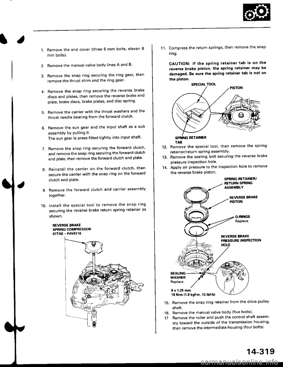
'10. lnstall the special tool to remove the snap ring
securing the reverse brake return spring retainer as
snown.
REVERSE BBAKESPRING COMPRESSOR07TAE - PaV0110
11. Compress the return springs. then remove the snap
ring
CAUTION: lf the spring retainer tab is on the
rsverse braks piston, tho spting letainer may be
damaged. Be surs the spring letainer tab is not on
the piston.
SPfiING FETAIiGRTAB
Remove the special tool, then remove the spring
retainer/return spring assembly.
Remove the sealing bolt securing the reverse brake
pressure insPection hole.
Apply air pressure to the inspection hole to remove
the reverse brake Piston
12.
13.
14.
16.'t7
SPBING REYAINER/RETURiI SPRIiIGASSEMALY
REVERSE BNAXEPISTON
o-RrllcsReplace.
FCVERSE BRAKEPRESSURE INS?ECTK)NHOtl
SEALINGWASHERReplace.
8 x 1.25 mm18 N.m 11.8 kgf.m, 13 lbf.ttl
Remove the snap ring retainer from the drive pulley
shaft.
Remove the manual valve body (five bolts)'
Remove the roller and push the control shaft assem-
bly toward the outside of the transmission housing,
then remove the intermediate housing (four bolts)'
SPECIAL TOOL
14-319
Page 1001 of 2189
Forward Glutch
Reassembly
NOTE:
. Clean all parts thoroughly in solvent or carburetor
cleaner, and dry them with compressed air.
. Blow out all passages.
. Lubricate all parts with CW Fluid before reassembly.
1. Inspect the check valve; if it's loose, replace the pis-
ton.
CHECK VALVE
Install new O-rings on the clutch pision.
PISTON
14-324
3. Install the piston in the clutch drum. Apply pressure
and rotate to ensure proper seatang,
NOTE: Lubricate the piston O-ring with CVT Fluid
before installing.
CAUTION: Do not pinch thc O-ring by installing the
pistoo with too much torqo.
CLUTCH DRUM
Install the return spring and spring retainer, and
position the snap ring on the retainer.
CLUTCH DRUM
Page 1014 of 2189
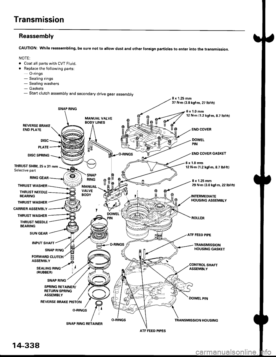
Transmission
Reassembly
CAUTION: While reassembling. be sure not to sllow dust and othor foreign particles to enter into the transmission.
NOTE:
. Coat all parts with CVT Fluid.
. Replace the following parts:- O-rings- Sealing rings- Sealing washers- Gaskets- Start clutch assembly and secondary drive gear assembly8 x 1.25 mm37 N.m {3.8 kgf.m,27 lbtftl
MANUAL VALVE
6x1.0mm12 N m 11.2 kgf.m,8.7 lbl.ft)
LINESREVERSE BRAKEEND PLATE
Dtsc
PLATE
DISC SPRING
THRUST WASHER
CARRIER ASSEMBLY
THRUST WASHER
THRUST NEEDLEBEARING
END COVEB
DOWELPIN
END COVER GASKET
6x1.0mm12 N.m 11.2 kgtm,8.7 lbtft)THRUST SHIM,25 x 31 mmSelective part
RING GEAR
THRUST WASHER
THRUSTBEARING
8 x 1.25 mm29 N.m 13.0 kgl m, 22 lbtftl
INTERMEDIATEHOUSING ASSEMBLY
ROLI.IR
SNAPRINGeBH^cMANUALVALVEBOOY
SUN GEAR
INPUT SHAFT
(RUBEERI
ATF FEED PIPE
O-RINGSTRANSMISSIONHOUSING GASKETSNAP RING
FORWARD CLUTCH
SNAP RING
SHAFTASSEMALY
DOWEL PtN
SPRING RETAINER/RETURN SPRINGASSEMBLY
REVERSE BRAKE PISTON
O.RINGS
SNAP RING
ATF FEED PIPES
14-338
SNAP RING RETAINERTRANSMISSION HOUSING
Page 1015 of 2189
1.
7.
lnstall the ATF feed pipe in the transmission hous-
ing, and install the three ATF feed pipes with new
O-rings in the transmission housing,
Install the two dowel pins and new transmission hous-
ing gasket on the transmission housing.
Push the control shaft assembly toward the outside
of the transmission housing, then install the inter-
mediate housing assembly (four bolts).
lnstall the manual valve body separator plate and
the two dowel pins on the intermediate housing,
then install the rnanual valve body with the detent
spring (five bolts).
Put the control shaft assembly back, then install the
roller in the intermediate housing.
lnstall the reverse brake piston in the intermediate
housing.
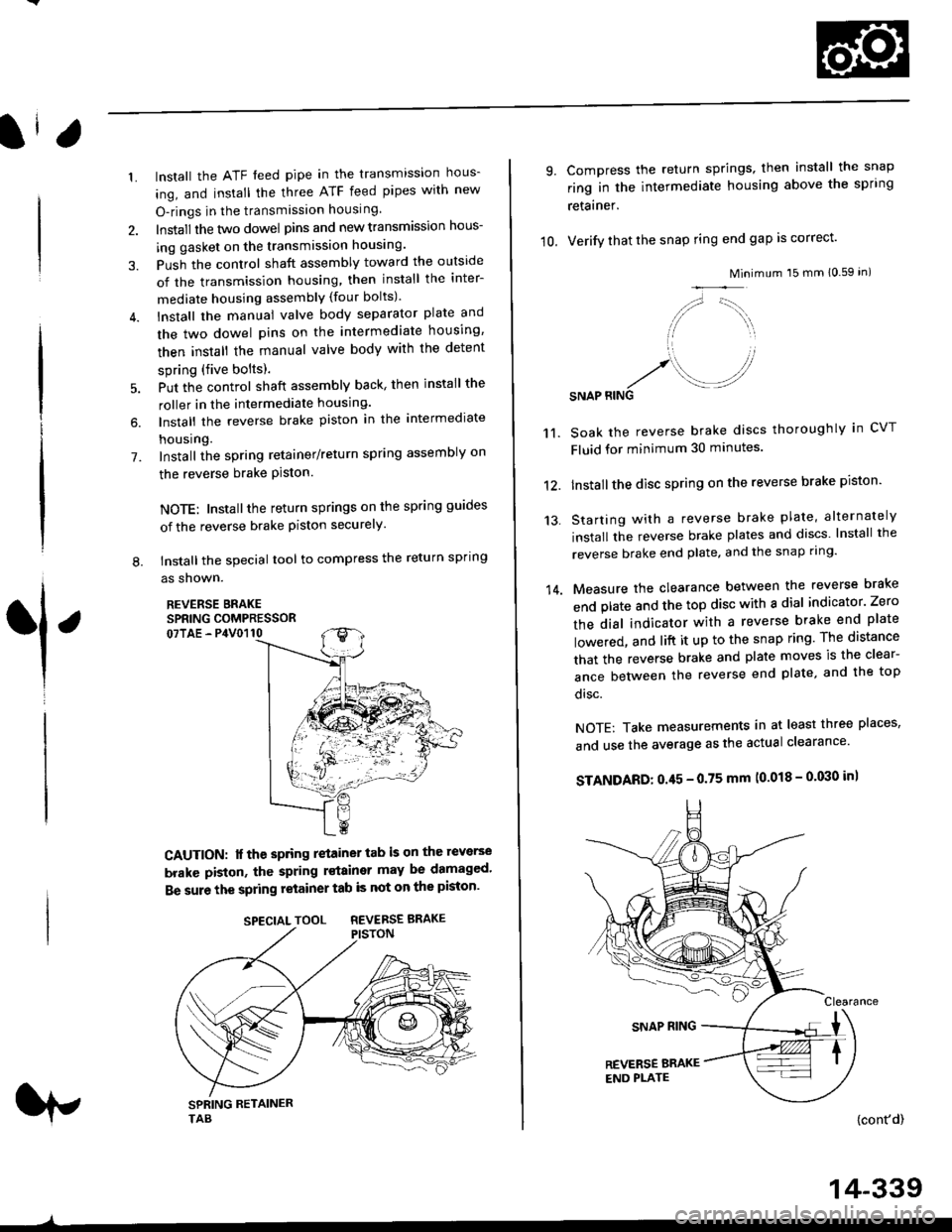
Install the spring retainer/return spring assembly on
the reverse brake Piston.
NOTE: Installthe return springs on the spring guides
of the reverse brake piston securely
tnstall the special tool to compress the return spring
as shown.
REVERSE BRAKESPRING COMPRESSOR07TAE - P4V0110
6.
L
1
CAUTION: lf the spring retainer tab is on the reverse
brakc piston, the spring rstainer may be damaged'
Be sure the spring retainer tab is not on the piston'
rp
SPECIALTOOL REVERSEBRAKE
-^
14-339
10.
9.
14.
Compress the return springs, then install the snap
ring in the intermediate housing above the spring
retainer.
Verify that the snap ring end gap is correct'
Mini
/,,- '-t,,,,.
// \i/ ',r
'1 ,
.r' //'/. .-J?RINGSNAP
mum 15 mm 10.59 in)
Soak the reverse brake discs thoroughly in CVT
Fluid for minimum 30 minutes.
Installthe disc spring on the reverse brake piston'
Starting with a reverse brake plate, alternately
install the reverse brake plates and discs lnstall the
reverse brake end plate, and the snap ring'
Measure the clearance between the reverse brake
end plate and the top disc with a dial indicator' Zero
the dial indicator with a reverse brake end plate
lowered, and lift it up to the snap ring The distance
that the reverse brake and plate moves is the clear-
ance between the reverse end plate, and the top
disc.
NOTE: Take measurements in at least three places'
and use the average as the actual clearance'
STANDARD: 0.45 - 0.75 mm (0.018 - 0'030 in)
{cont'd)
11.
12.
13.
Page 1115 of 2189
)
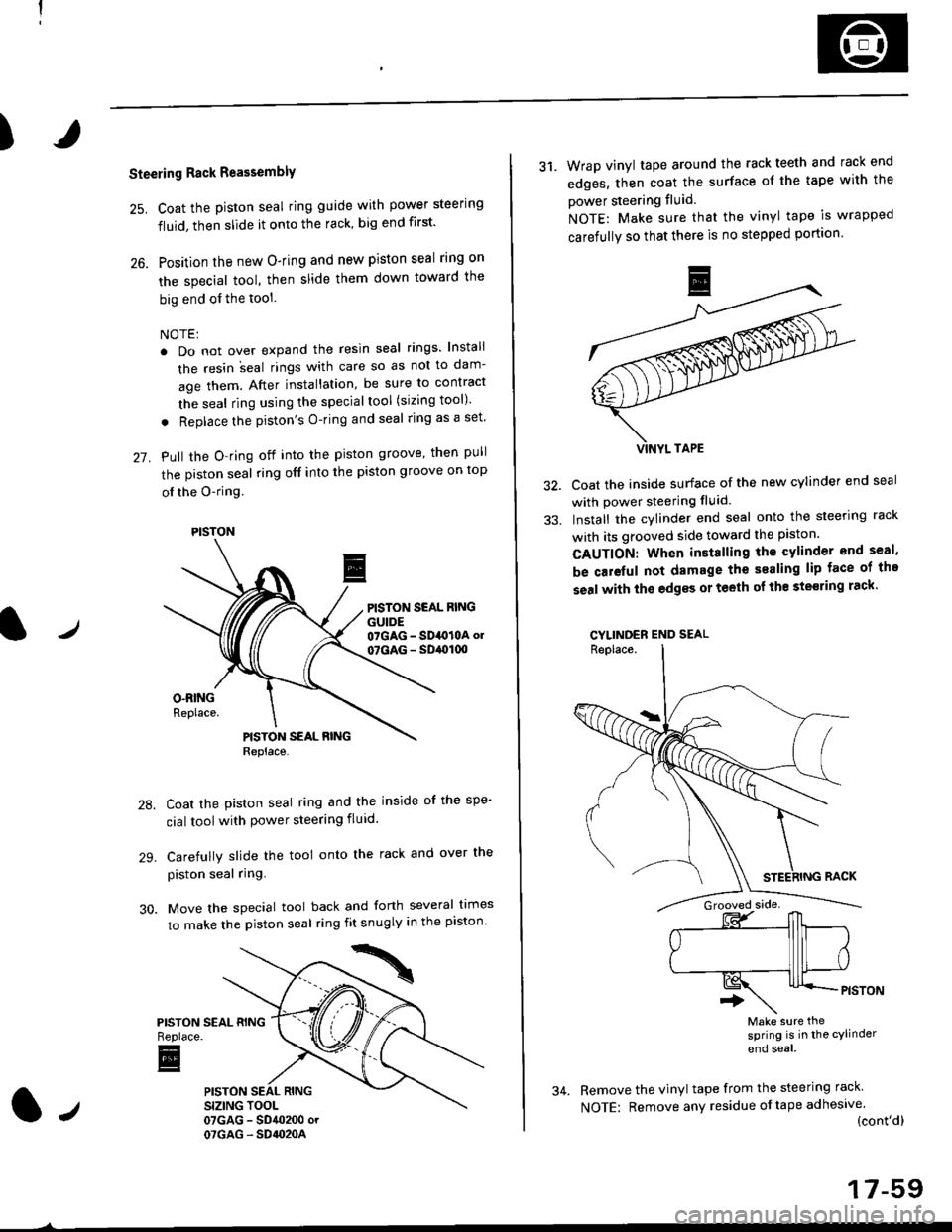
Steering Rack Reassembly
25. Coat the piston seal ring guide with power steering
fluid, then slide it onto the rack, big end first'
26. Position the new O-ring and new piston seal rlng on
the special tool, then slide them down toward the
big end of the tool
NOTE:
. Do not over expand the resin seal rings lnstali
the resin ;eal rings with care so as not to dam-
age them. After installation, be sure to contract
the seal ring using the specialtool (sizing tool)
. Replace the piston's O-ring and seal ring as a set'
27. Pull the O-ring off into the piston groove, then pull
the piston seal ring off into the piston groove on top
ol the O-ring
PISTON SEAL RINGGUIDE07GAG - SD4O10A ol
07GAG - SD,ol(xt
Coat the piston seal ring and the inside of the spe-
cial toolwith power steering fluid.
Carefully slide the tool onto the rack and over the
piston seal ring.
Move the special tool back and forth several times
to make the piston seal ring fit snugly in the piston'
PISTONReplace.
E
PISTON
31. Wrap vinyl tape around the rack teeth and rack end
edges, then coat the surface of the tape with the
power steering fluid
NOTE: Make sure that the vinyl tape is wrapped
carefully so that there is no stepped portion
Coat the inside surface of the new cylinder end seal
with power steering fluid.
Install the cylinder end seal onto the steering rack
with its grooved side toward the piston.
CAUTION: When installing the cylinder end seal,
be caieful not damage the sealing lip face of tho
seal with the edgss or teeth of th€ ste€ring rack'
CYLINDER END SEAL
Make sure thesPring is in the cylinder
end soal
Remove the vinyl tape from the steering rack
NOTE: Remove any residue oftape adhesive(cont'dl
17-59