2000 HONDA CIVIC Pcv valve
[x] Cancel search: Pcv valvePage 294 of 2189

|-
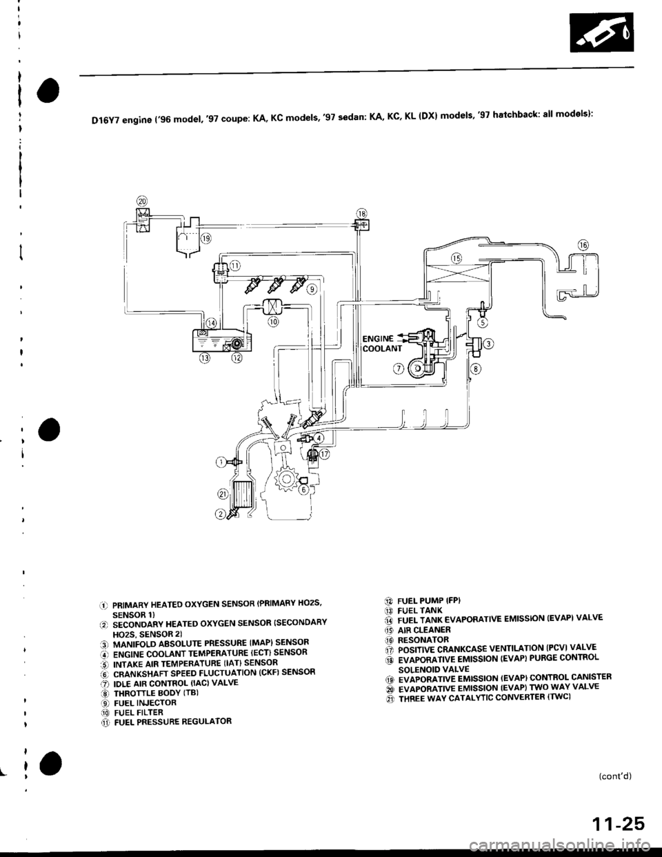
DI6YTengine('96mode|.,97coupe:KA,Kcmode|s,,97sedan:KA,KC,KL{Dx}modets,'gThatchback:a||models}:
COOLANT
o
l)
r.-.
.t)
a:!)
o-o
aroa1t
PRIMARY HEATED OXYGEN SENSOR (PRIMARY HOzS,
SENSOR 1)SECONDARY HEATED OXYGEN SENSOR {SECONDARY
HOzS, SENSOR 2)
MANIFOLD AESOI-UTE PRESSURE IMAP) SENSOR
ENGINE COOLANT TEMPERATURE IECT) SENSOR
INTAKE AIR TEMPERATURE (IAT} SENSOR
CRANKSHAFT SPEED FLUCTUATION (CKF) SENSOR
IDLE AIR CONTROL (IACI VALVE
THROTTLE BOOY (TB)
FUEL INJECTORFUEL FILTERFUEL PRESSURE REGULATOR
FUEL PUMP IFPIFUEL TANKFUEL TANK EVAPORATIVE EMISSION (EVAPI VALVE
AIR CLEANERRESONATORPOSITIVE CRANKCASE VENTILTATION IPCVI VALVE
EVAPORATIVE EMISSION (EVAP} PURGE CONTROL
SOLENOID VALVEEVAPORATIVE EMISSION (EVAP) CONTROL CANISTER
EVAPORATIVE EMISSION IEVAPI TWO WAY VALVE
THREE WAY CATALYTIC CONVERTER (TWCI
[3)@ao(o
a@
(0
@)
(cont'd)
11-25
Page 295 of 2189
![HONDA CIVIC 2000 6.G Workshop Manual System Description
Vacuum Connections (contd)
Dl6Y7 angin6 (97 coup.: KL mod€l, sedan: KL (LX) model,,9g modet):
i1] PRIMARY HEATED OXYGEN SENSOR (PRIMARY HO2S,SENSOR 1)E) SECONDARY HEATED OXYGEN HONDA CIVIC 2000 6.G Workshop Manual System Description
Vacuum Connections (contd)
Dl6Y7 angin6 (97 coup.: KL mod€l, sedan: KL (LX) model,,9g modet):
i1] PRIMARY HEATED OXYGEN SENSOR (PRIMARY HO2S,SENSOR 1)E) SECONDARY HEATED OXYGEN](/manual-img/13/6068/w960_6068-294.png)
System Description
Vacuum Connections (cont'd)
Dl6Y7 angin6 ('97 coup.: KL mod€l, sedan: KL (LX) model,,9g modet):
i1] PRIMARY HEATED OXYGEN SENSOR (PRIMARY HO2S,SENSOR 1)E) SECONDARY HEATED OXYGEN SENSOR {SECONDARYHO2S, SENSOR 2l€l MANTFOLD ABSOT_UTE PRESSUnE tMAp) SENSOR€r ENGINE COOLANT TEMPERATURE |ECT) SENSOR€] INTAKE AIR TEMPERATURE IIAT} SENSOR6 CRANKSHAFT SPEED FLUCTUATION ICKFI SENSOR17 IOLE AIR CONTROL IIACI VALVE@ THRoTTLE BoDY {TBIO FUEL INJEGToR(9 FUE|- FTLTEFO FUEL PRESSURE REGULAToR@ FUEL PUMP {FPI(D FUEL TANK@ FIFL TANK EVAPoRATIVE EMIssIoN {EVAPIVALVE(, AIR CLEANER
(tO RESONATORl? PoSITIVE cRANKcAsE VENTILATIoN IPcv}VALVEIA EVAPORANVE EMISSION TEVAPI PURGE CONTROLSOLENOID VALVE19 EVAPORATIVE EMISSION IEVAPI CONTROL CANISTERE EVAPORATIVE EMISSION (EVAPIBYPASS SOLENOIDVALVE€' EVAPoRATIVE EMIssIoN IEVAPI THREE wAY vALvEQ' EVAPORATIVE EMISSION IEVAPI CONTROL CANISTERVENT SHUT VALVE@ FUEL TANK PRESSURE sENsoR{?1! EVAPORANVE EMISSION IEVAPI TWO WAY VALVE?5 THREE WAY CATALYTIC CONVERTER ITWC'
11-26
Page 296 of 2189

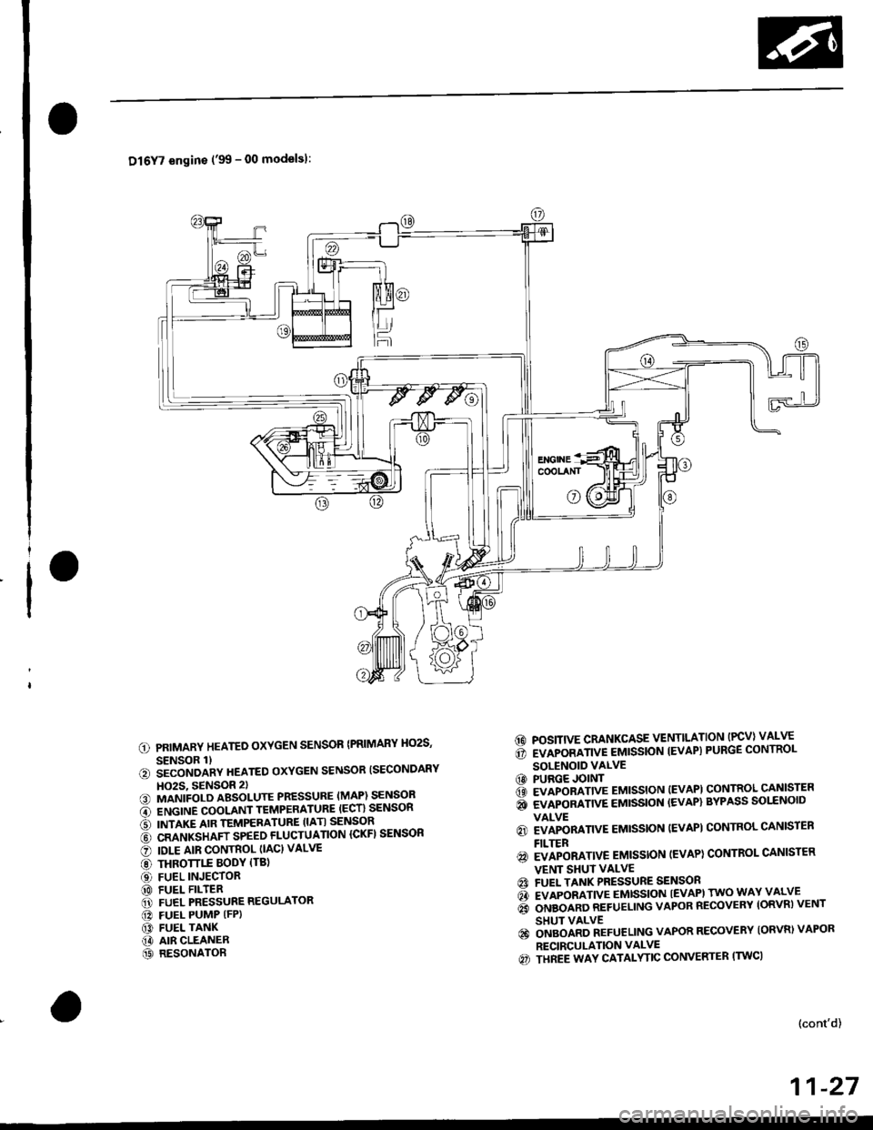
Dl6Y7 engins ('99 - 00 modelsl:
PRIMARY HEATED OXYGEN SENSOR {PRIMARY HO2S,
SENSOR 1)iiconoanv neareo oxYGEN sENsoR ISECoNDARY
HO2S, 9ENSOR 2)MANIFOLD ABSOLUTE PRESSURE (MAP) SENSOR
ENGINE COOLANT TEMPERATURE (ECT} SENSOR
INTAKE AIR TEMPERATURE (IATI SENSOR
CRANKSHAFT SPEED FLUCTUATION ICKFI SENSOR
IOLE AIR CONTROL (IAC} VALVE
THROTTLE BODY (TBl
FUEL INJECTORFUEL FILTERFUEL PRESSURE REGULATOR
FUEL PUMP (FP)
FUEL TANKAIR CLEANERRESONATOR
6d POSITIVE CRANKCASE VENTILATION (PCV) VALVE
6 rvapoamve eutssloN tEvAP) PURGE coNTRoL
SOLENOID VALVECO PURGE JOINT6 evlponnnve eutssloN (EvAPl coNTRoL cANlsrER
i evlponnnve eussloN {EVAP} BYPASS solrNolD
VALVE
6) EVAPORATIVE EMISSION (EVAPI CONTROL CANISTEN
FILTER
@ EVAPORATIVE EMISSTON (EVAP) CONTROL CANISTER
VENT SHUI VALVEA FUEL TANK PRESSURE SENSON
d rvlpoamve emtsstoN tEvAPl rwo wAY vALvE
6 orueonno nerueLING vAPoR REcovERY loRvnl vENT
SHUT VALVE
€) ongolno neruellNc VAPOR RECOVERY {ORVR) VAPOR
RECIRCULATION VALVE
€) THREE WAY CATALYTIC CONVERTER (TWC)
a
6t
@!.,
o@ao
@@
(}
@@
(cont'd)
11-27
Page 297 of 2189

I
a
System Description
Vacuum Connections (cont'd)
816A2 engine:
@ EvApoRATtvE EMtsstoN tEvAp) puRGE coNTRoLSOLENOID VALVE@ PURGE JoINT€t EvApoRATtvE EMtsstoN (EVApt coNTRoL caNtsTERQA EVAPORATIVE EMISSION (EVAP) BYPASS SOLENOIDVALVE
@ EVApoRATtvE EMtsstoN lEvApl coNTRoL caNtsrERFILTER@ EvApoRATtvE EMtsstoN {EvApt coNrRoL cANtsrERVENT SHUT VALVE@ FUEL TANK PRESSURE sENsoRGI EVAPORATIVE EMISSION (EVAP} TWO WAY VALVE@ ONBOARD REFUETING VAPOR RECOVERY {ORVR} VENTSHUT VALVE@ oNBoAnD REFUELING vApoR REcovERy (oRvRl vApoR. RECIRCULATION VALVE(c} THREE WAY CATALYTIC CONVERTER {TWCI
(' PRIMARY HEATED OXYGEN SENSOR IPRIMARY HO2S.SENSOR 1l.?) SECONDARY HEATED OXYGEN SENSOR {SECONDARYHO2S, SENSOR 2)13] MANIFOLD ABSoLUTE PRESSURE (MAP) sENsoBi' ENGINE COOLANT TEMPERATURE IECT) SENSORO INTAKE AIR TEMPERATURE ITATI SENSORi6l KNOCK SENSOR {KS}O oRANKSHAFT SPEED FLUCTUATIoN {cKF} sENsoR@ IDLE AIR coNTRoL (IAc} VALVE€) THRoTTLE BoDy trB|(D FUEL INJECToRO FUEL PULSATIoN DAMPER[D FUEL FILTER@ FUEL PRESSURE REGULAToR!I FUEL PUMP IFP)f,' FUEL TANK(iD ArR CLEANERt' RESONAToR'.1]i POSITIVE cRANKcAsE VENTILATIoN {Pcv} VALVE
11-28
Page 489 of 2189

ldle Control System
ldle Speed Setting
Inspection/Adiustmenl
'96, '97 Dl6Y5. '96 - 00 Dl5Y8 sngine with M/T
NOTE:
. Before setting the idle speed, check the following
items:- The MIL has not been reported on.- lgnition timing- Spark plugs- Air cleaner- PCV system
o (Canada) Pull the parking brake lever up. Start the
engine, then check that the headlights are off.
1. Start the engine. Hold the engine at 3.000 rpm withno load (taansmission in neutral) until the radiatorfan comes on, then let it idle.
2. Connect a tachometer.
3. Disconnect the IAC valve connector.
4.lf the engine stalls, restart the engine with the accel-
erator pedal slightly depressed. Stabilize the rpm at1,000, then slowly release the pedal until the engineidles.
Check idling in no-load conditionsr headlights. blowerfan. rear defogger, radiator fan, and air conditioner
are not operating.
ldle spsed should be:
450 1 50 rpm
11-220
Adjust the idle speed, if necessary, by removing thecap and turning the idle adjusting screw.
NOTE; After adjusting the idle speed in this step,recheck the ignition timing (see section 23).
lf it is out of spec, go back to step 4.
IDLE
6. Turn the ignition switch OFF.
7. Reconnect the 2P connector on the IAC valve, then
do the ECM reset procedure.
8. Restart and idle the engine with no-load conditionsfor one minute, then check the idle speed.
NOTE: (Canada) Pull the parking brake lever up.Start the engine, then check that the headlights areoff.
ldle sp€sd should b€:
670 i 50 rpm IUSA)750 t 50 rpm {Canada}
9. ldle the engine tor one minute with headlights {Low)ON. and check the idle speed.
ldle speed should be:
750 :r 50 rpm
10. Turn the headlights off. ldle the engine for oneminute with heater fan switch at Hl and air conditioneron, then check the idle speed.
ldle speed should be:
810150 rpm
NOTE: lf the idle speed is not within specification,see Symptom Chan on page 11-84.
Page 490 of 2189

t
t
I
'96.'97 D16Y5 engine with CVT,'96 - 00 D16Y8 ongins
with A/T and'96 - 00 Dl6Y7 €ngine
Adiust the idle speed using a Honda PGM Tester if pos-
sible. lf not, use the following procedure:
NOTEI
. Leave the IAC valve connected
. Betore setting the idle speed. check the following
items:- The MIL has not been reported on'
- lgnition timing
- Spark Plugs- Air cleaner- PCV system
1. Connect a tachometer.
2. Start the engine. Hold the engine at 3,000 rpm wirh
no load (in Park or neutral) until the radiator fan
comes on, then let it idle.
3. Check the idle speed with no-load conditions: head-
iights, blower fan, rear defogger, radiator fan, and
air conditioner are not operatlng
ldl€ spoed should be:
USA:
D16Y5 engine with CVT, D16Y7 engine with A/T'
Dl6YB engine with A/T:
700 :r 50 rpm (in E or El Positionl
D16Y7 engine with M/T:
670 i 50 rpm
Canada:
Dl6Y8 sngin€, Dl6Y7 engins:
M/T750 t 50 rpm
NT750 1 50 rpm (in E or El Position)
Adjust the idle speed, if necessary, by removing the
cap and turning the idle adiusting screw 1/2-turn
clockwise or counterclockwise
D16Y5, D16Y8 engine:
IDLEADJUSTING
Dl6f, ongine:
NOTE: When you remove the ACL housing, do not
disconnect the IAT sensor connector
After turning the idle adjusting scrow 1/2-turn'
check the idle speed again. lf it is out of spec, turn
the idle adjusting screw 1/2-turn agaan'
NOTE: Do not turn the idle adjusting screw more
than 1/2-turn without checking the idle speed'
ldle the engine for one minute with heater fan
switch at Hl and air conditioner on, then check the
idle speed.
ldle speed should be:
M/T810150 rpm
A/T. CvT810 t 50 rpm (in El or E Position)
NOTE:
. Do not turn the idle adjusting screw when the air
conditioner is on.
. lf the idle speed is not within specification. see
Symptom Chart on page 11-84 (cont'd)
11-221
Page 491 of 2189

ldle Control System
ldle Speed Setting (cont'dl
Inspeqtion/Adiustment
38 D16Y5 engine whh M/T,'99 - 00 81642 engine
NOTE: Before setting the idle speed, check the follow-ing items;- The MIL has not been reported on.- lgnition timing- Spark plugs- Air cleaner- PCV system
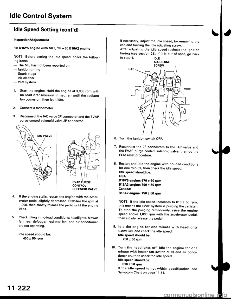
'1. Start the engine. Hold the engine at 3,000 rpm withno load (transmission in neutral) until the radiatorfan comes on, then let it idle.
Connect a tachometer.
Disconnect the IAC valve 2P connector and the EVAPpurge controlsolenoid valve 2P connector.
EVAP PURGECONTROLSOLENOID VALVE
lf the engine stalls, restart the engine with the accel-erator pedal slightly depressed. Stabilize the rpm at1.000, then slowly release the pedal until the engineidles.
Check idling in no-load conditions: headlights, blowerfan, rear defogger, radiator fan, and air conditionerare not operating.
ldl€ speed should be:
450 i 50 rpm
11-222
lf necessary, adjust the idle speed, by removrng lnecap and turning the idle adjusting screw.After adjusting the idle speed recheck the ignitlontiming (see section 23). lf it is out of spec, go backto step 4. |DLE
6. Turn the ignition switch OFF.
7. Reconnect the 2P connectors to the IAC valve andthe EVAP purge control solenoid valve, then do theECM reset procedure.
8. Restart and idle the engine with no-load conditionsfor one minute, then check the idle sDeed.ldle speed should bo:
USA:
D16Y5 engine: 670 i 50 rpm
81642 engine: 700 i 50 rpm
Canada:
81642 engine: 750 t 50 rpm
NOTE: lf the idle speed increases to 8lO t 50 rpm,this means the EVAP system is purging the canister.To stop the purging temporarily, raise the enginespeed above 1,000 rpm with the accelerator pedal,
then slowly release the pedal.
9. ldle the engine for one minute with headlights(Low) ON. and check the idle speed.
ldle speed should be:
750 i 50 rpm
10. Turn the headlights off. ldle the engine for oneminute with heater fan switch at Hl and air condi-tioner on, then check the idle soeed.ldls speed should be:
810 t 50 rpm
lf the idle speed is not within specification, seeSymptom Chart on page 11-84.
Page 492 of 2189

\
I
'98 - 0O D16Y5 ongine with CvT
Adjust the idle speed using a Honda PGM Tester if pos-
sible. lf not, use the following procedure:
NOTE:
. Leave the IAC valve connected.
. Before s€tting the idle speed, check the following
rtems:- The MIL has not been reported on.
- lgnition timing
- Spark Plugs- Air clean€r
- PCV svstem
'1. Connect a tachometer.
2. Stan the engine. Hold the engine at 3,000 rpm w'th
no load (transmission in E or E] position) until the
radiator Jan comes on, then let it idle.
3. Check the idle speed under no-load conditions:
head lights, blower fan, rear defogger, radiator fan,
and air conditioner are not operatlng.
ldlo spaod ehould bo: 700 t 50 rpm
. lf the idle speed is within the specification, the
procedure is comPlete.
. lf the idle sDeed is out of specitication, 9o to step 4'
4. tf the idle speed is 810 1 50 rpm, this means the
EVAP system is purging the canister. To stop the
purging temporarily, raise the engine speed above
l,OO0 rgm with the accelsrator pedal. Slowly release
the pedal. and rscheck the idl€ speed.
. tf the idle speed is within the specificstion, the
Drocedure is comPlete.
. lf the idle sp€ed is out of spocification, go to step 5.
5. Disconnect th€ EVAP purgs control solenoid valve
2P connector.
EVAP PURGECONTROL
6. Remove the cap and turn the idle adiusting screw
1/2-turn clockwise or counterclockwlse
IDLE
7.After turning the idle adjusting screw 1/2-turn, check
the idl€ speed again. lf it is out of spec, turn the idle
adjusting screw 1/2-turn again.
NOTE: Do not turn the idle adjusting screw more
than 1/2-turn without checking the idle speed.
Turn the ignition switch OFF. Reconnect the EVAP
purge control solenoid valve 2P connector' then do
the ECM reset Procedure.
Start the engine. ldle the engine for one minute with
heater fan switch at Hl and air conditioner on, then
check the idle speed.
ldle spaed should be:
810 t 50 rpm (in El or E Posiiion)
lf the idle speed is not within specification, see
Svmptom Chart on Page 11-84.
9.
SOLENOID VALVE
11-223