Page 124 of 2189
6. Tighten the locknut, and check the clearance again.
Repeat the adjustment if necessary.
GAUGE
7.Rotate the crankshaft 180' counterclockwise (cam-
shaft oullev turns 90'1. The "UP" mark should be on
the exhaust side. Adjust valves on No. 3 cylinder.
"UP- MARK
t
8. Rotate the crankshaft '180' counterclockwise to
bring No.4 piston to TDC. Both TDC grooves are
once again visible. Adjust valves on No. 4 cylinder.
Rotate the crankshaft 180'counterclockwise to bring
No. 2 piston to TDC. The "UP" mark should be on
the intake side. Adjust valves on No. 2 cylinder.
-UP'MARK
6-13
Page 140 of 2189

13. Remove the upper radiator hose' heater hose and
water bYPass hose
WATEREYPASSHOSEUPPERRADIATORHOSE
14.
HEATERHOSE
Remove the engine wire harness connectors and
wire harness clamps from the cylinder head and the
intake manifold.
o Four fuel injector connectors
. Engine coolant temperature (ECT) sensor con-
nector
a
a
a
ECT switch connector
ECT gauge sending unit connector
Throttle position sensor connector
Manitold absolute pressure (MAP) sensor con-
nector
Primary heated oxygen sensor (primary HO2S)
connector
Secondary heated oxygen sensor (secondary
HO2S) connector (D16Y7 engine)
Exhaust gas recirculation (EGR) valve lift sensor
connector (D16Y5 engine)
. VTEC solenoid valve connector (Dl6Y5, D16Y8
engrnes)
. VTEC pressure switch connector (D16Y5. D16Y8
engrnes,
. ldle air control (lAC) valve connector
15.Remove the spark plug caps and distributor from
the cylinder head.
Remove the uPPer bracket.
NOTE:
. Use a jack to support the engine before the
upper bracket is removed.
. Make sure to place a cushion between the oil
pan and the jack.
12 x 1.25 mm
74 N.m {7.5 kgf m.
sil lbl.ftl
UPPERBRACKET
'17. Remove the cylinder head cover'
CYLINDERHEAD COVER
(cont'd)
6-29
Page 146 of 2189
Rocker Arms and Shafts
Clearance Inspection
Measure both the intake rocker shaft and exhaust rocker
shaft.
1. Measure the diameter of the shaft at the first rocker
locatron.
2. Zero the gauge to the shaft diameter'
I
3. Measure the inside diameter of the rocker arm and
check for an out of-round condition.
Rockel Arm-to-Shaft Clearance
Standard (Newl:
lntake: 0.017 - 0.050 mm
{0.0007 - 0.0020 inl
Exhaust: 0.018 - 0.054 mm
(0 0007 - 0 0021 in)
Service Limit:0.08 mm {0.003 inl
Repeat these measurements on all the rockers.
- lf the clearance is over the service limit, replace the
rocker shaft and all over tolerance rocker arms.
6-35
Page 150 of 2189

Valve Guides
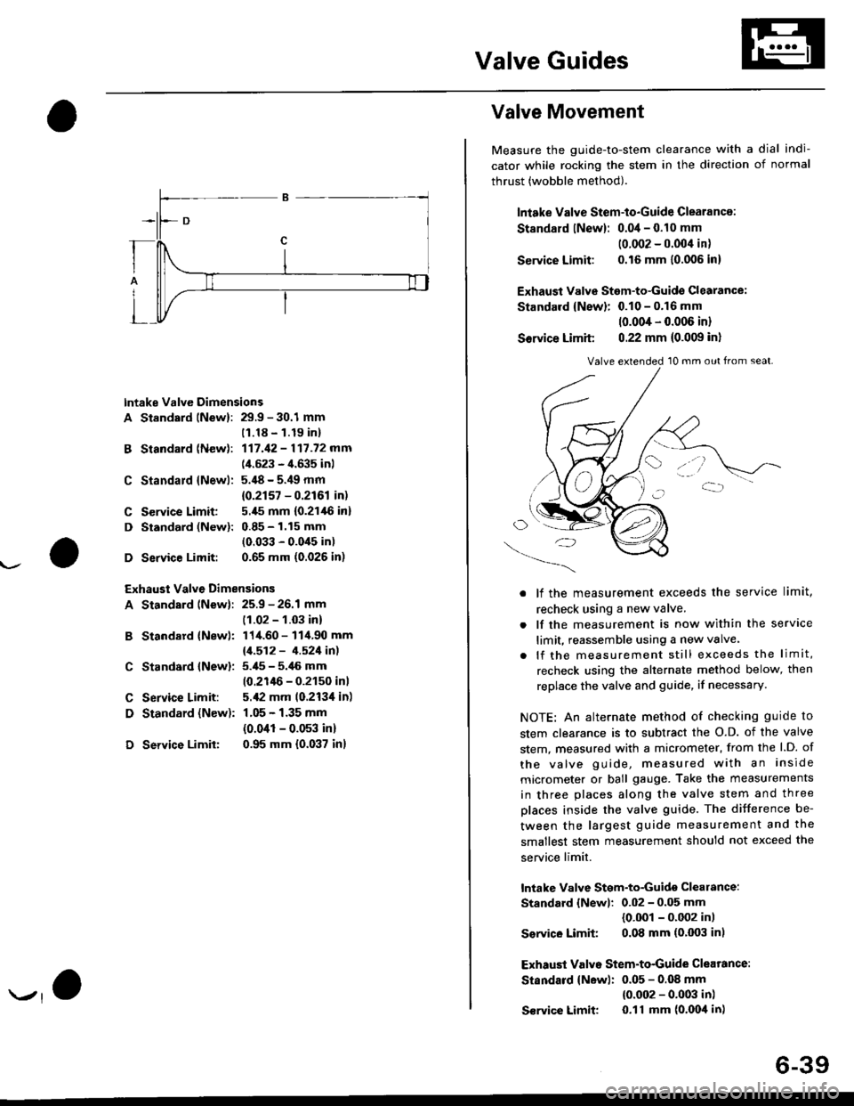
lntake Valve Dimensions
A Standsrd lNewl: 29.9 - 30.1 mm
B Standard (New):
C Standald {Newl:
C Service Limit:
D Standard (New):
D Service Limit:
11.18 - 1.19 inl
117.42 - 117.72 mm
(4.523 - 4.635 inl
5.'18 - 5.49 mm
{0.2r57 - 0.2r61 in)
5.,[5 mm (0.21,16 in]
0.85 - 1.15 mm
(0.033 - 0.0'15 in)
0.65 mm (0.026 in)
Exhaust Valve Dimensions
A Standard lNew): 25.9 - 26.1 mm
B Standard {Newl:
C Standard {New):
C Service Limit:
D Standard {New):
D Service Limit:
(1.02 - 1.03 in)
114.60 - 114.90 mm
11.512 - 4.521in1
5.i[5 - 5.46 mm
10.21lt6 - 0.2150 inl
5.,12 mm 10.213'l in)
1.05 - 1.35 mm
{0.041 - 0.053 in)
0.95 mm {0.037 in}
Valve Movement
Measure the guide-to-stem clearance with a dial indi-
cator while rocking the stem in the direction of normal
thrust (wobble method).
lniake Valve Stem-to-Guide Clearance:
St8ndard lNew): 0.04 - 0.10 mm
10.002 - 0.004 in)
Service Limit: 0.16 mm 10.006 in)
Exhaust Valvs Stem-to-Guide Glearance:
Standard {New}: 0.10 - 0.16 mm
10.004 - 0.006 in)
Sorvice Limit 0.22 mm (0.009 in)
O/'-_)
. lf the measurement exceeds the service limit,
recheck using a new valve.
. lf the measurement is now within the service
limit, reassemble using a new valve.
. lf the measurement still exceeds the limit,
recheck using the alternate method below, then
replace the valve and guide, if necessary.
NOTE: An alternate method of checking guide to
stem clearance is to subtract the O.D. of the valve
stem, measured with a micrometer, from the l.D. of
the valve guide, measured with an inside
micrometer or ball gauge. Take the measurements
in three places along the valve stem and three
places inside the valve guide. The difference be-
tween the largest guide measurement and the
smallest stem measurement should not exceed the
service limit.
lntake Valve Stgm-to-Guidg clearance:
Standard {Newl: 0.02 - 0.05 mm
{0.001 - 0.002 in)
Ssrvico Limit 0.08 mm (0.003 in)
Exhaust Valvo Stem-to-Guide Clearance:
Standard {New): 0.05 - 0.OB mm
{0.002 - 0.003 in)
S€rvice Limit 0.11 mm (o'Ooil in)
Valve extended 10 mm out from seat.
6-39
Page 162 of 2189

VTEC Control System
Troubleshooting Flowchart (cont,d)
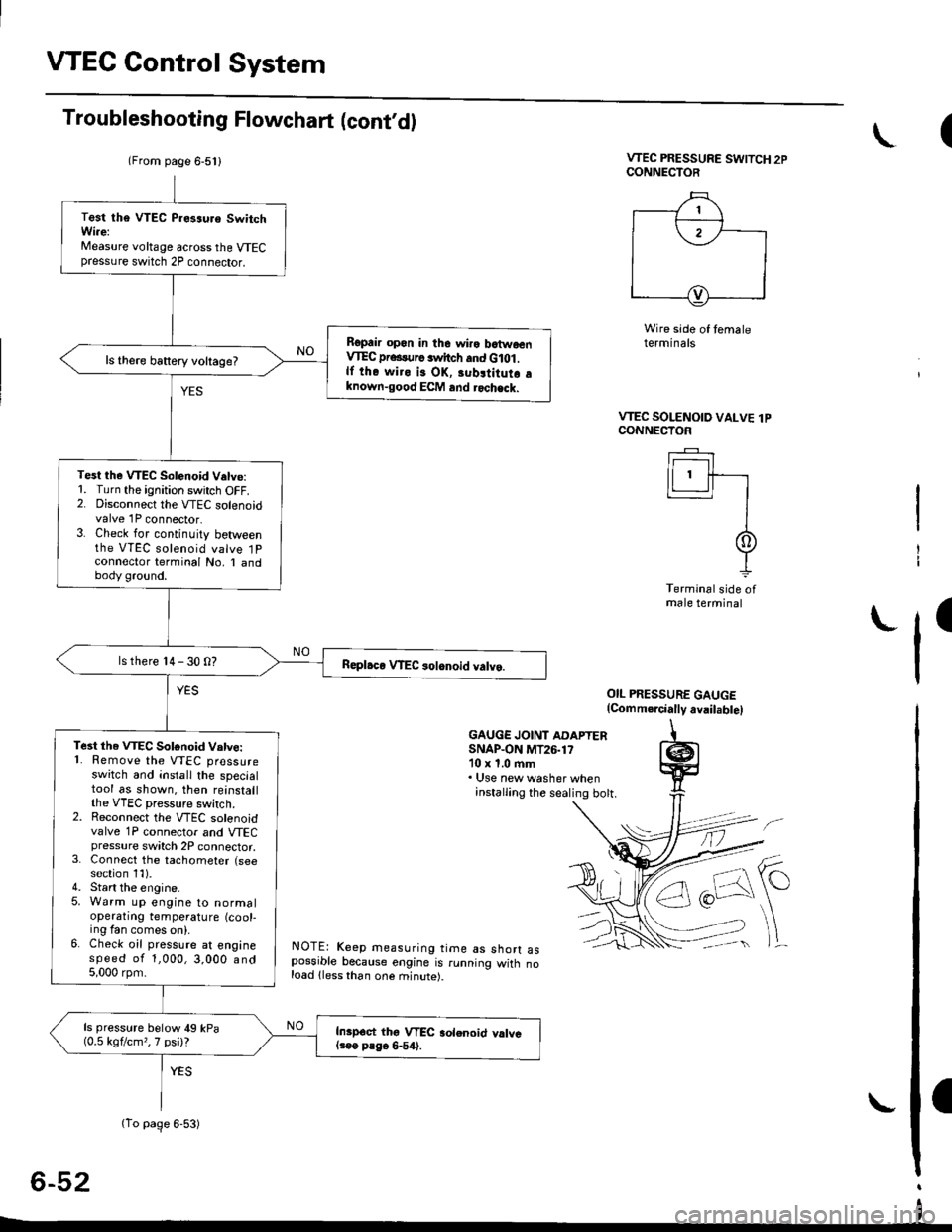
VTEC PRESSURE SWITCH 2PCONNECTOR
Wire side of temaleterminals
OIL PRESSURE GAUGE(Comm.rcially avail.bte)
GAUGE JOINT ADAPTERSNAP.ON MT26.1710 x 1.0 ftm. Use new washer wheninstalling the sealing bott.
NOTE: Keep measuring time as shorr aspossible because engine is running witn noload lless than one minute).
6-52
(
VTEC SOLENOID VALVE lPCONNECTOF
Ir------r I
lLl.ll-r
II
It
Terminal side ofmale terminal
I
(From page 6-5l l
(To page 6-53)
Test tha VTEC P.es3uro SwitchWi.e:Measure voltage across the VTECpressure switch 2P connector.
Ropair opon in the wiro batwoenVIEC pr...urc switch and G lot .lf the wiro is OK, 3ubltitutr aknown-good ECM and rochack.
ls there battery voltage?
Test the VTEC Solenoid V.tve:1. Turn the ignition switch OFF.2. Disconnect the VTEC solenoidvalve 1P connector.3. Check for continuity betweenthe VTEC solenoid valve 1Pconnector terminal No, I andbody ground.
ls there 14 - 30 O?
Te3t the VTEC Sotonoid Vatve:'1. Remove the VTEC pressureswitch and install the specialtool as shown. then reinstallthe VTEC pressure switch.2. Reconnect the VTEC solenoidvalve 1P connector and VTECpressure switch 2P connector,3. Connect the tachometer (seesection 1l).4. Start the engine.5. Warm up engine to normaloperatrng temperature (cool-ing fan comes on).6. Check oil pressure at enginespeed of 1,000,3,000 and5,000 rpm.
ls pressure below 49 kPa(0.5 kgflcm,,7 psi)?Inipoct thg VTEC aolenoid valvel3ee P8go 6-54).
I
Page 165 of 2189

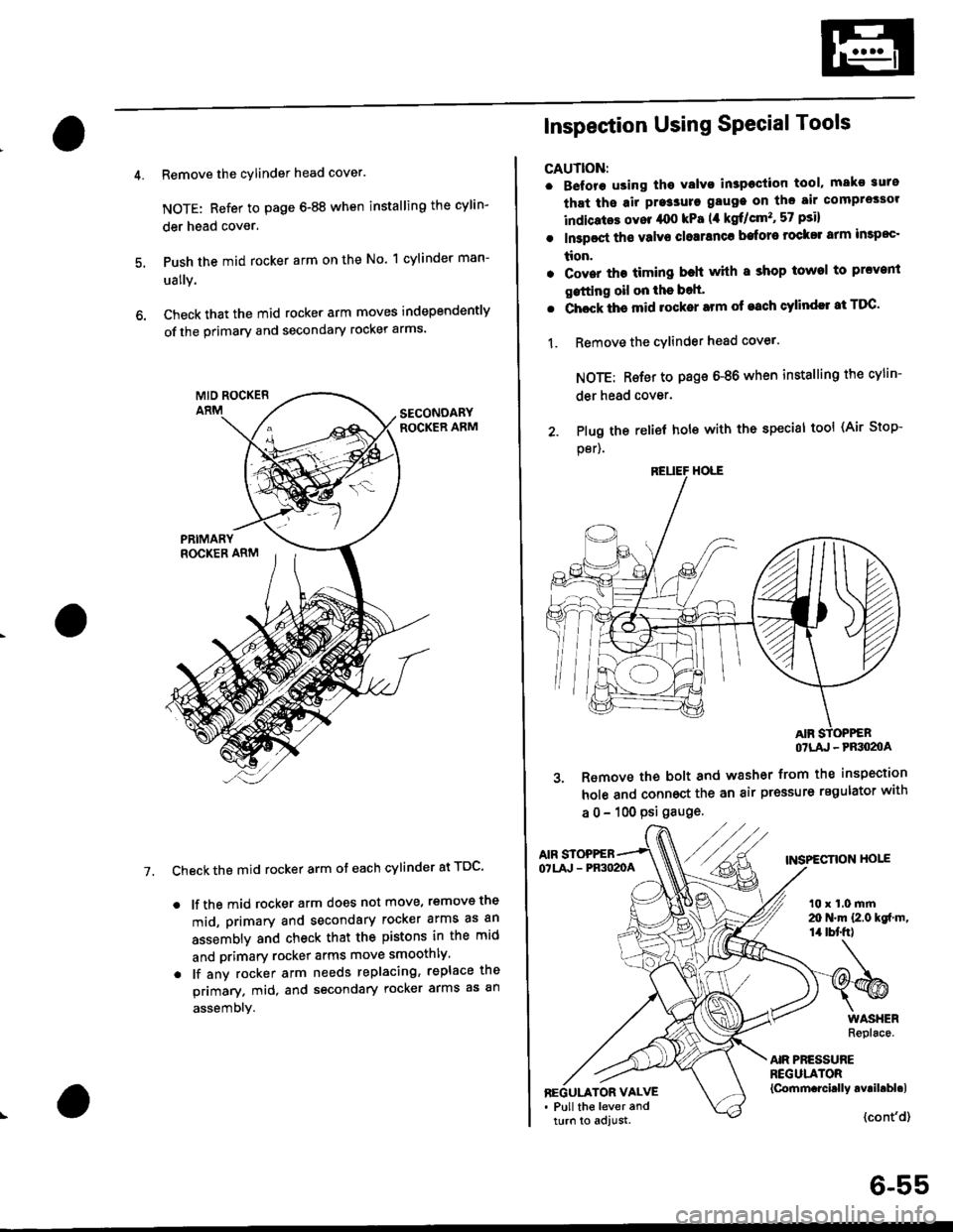
Remove the cylinder head cover.
NOTE: Refer to page 6-88 when installing the cylin-
der head cover.
Push the mid rocker arm on the No. 1 cylinder man-
ually.
Check that the mid rocker arm moves independently
of the primary and secondary rocker arms.
Check the mid rocker arm ot each cylinder at TDC'
. lf the mid rocker arm does not move, removs the
mid, primary and secondary rocker arms as an
assembly and check that the pistons in the mid
and primary rocker arms move smoothly.
. lf any rocker arm needs replacing, replace the
primary. mid, and secondary rocker arms as an
assembly.
7.
2. Plug the
per).
Inspection Using SPecial Tools
CAUTION:
. B€fore using tho Yalvo inspeciion tool, mako suro
that ths air pre3sure gauge on the air comprossor
indicatos ovor /rco kPa (,1 kgf/cm'�, 57 psi)
. In3poct ths valve closranca bafore rock$ arm impoc'
tion.
. Cover the timing beh whh I shop towel to prcvenl
gstting oil on the bolt'
. Chock ths mid rocker arm of each cylindll at TDC'
1. Remove the cYlinder head cover.
NOTE: Rsfer to page 6-86 when installing the cylin-
der head cover.
relief hole with the special tool (Air Stop-
OTLA' - PRSO2OA
3. Remove the bolt and washer from the inspection
hole and connoct the an air pressure regulator with
a 0 - 100 psi gauge.
AIF STOPPEBTNSPECTION HOIEOTLA' - PR3O2OA
t0 x 1.0 mrn20 N.m {2.0 kgf m,14 tbt'fr)
AIR PRESSUREREGULATOR{Cornm.rcirlly avril.bl.lBEGULATOR VALVE. Pull the lever andturn to adjust.{cont'd}
6-55
Page 167 of 2189

Valve Glearance
Adjustment
NOTE:
. Valves should be adjusted only when the cylinder
head temperaturs is less than 100'F (38'C)'
. After adjusting, retorque the crankshaft pulley bolt to
177 N.m (18.0 kgf'm, 130 lbt'ft)
1. Remove the cylinder head cover'
NOTE: Refer to page G86 when installing the cylin-
der head cover.
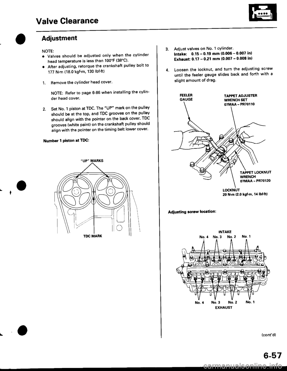
2. Set No. 1 pi$on at TDC. The "UP" mark on the pullsy
should be at the top, and TDC grooves on the pulley
should align with the pointer on the back cover' TDC
grooves {white paint) on the crankshaft pulley should
align with the pointer on the timing belt lower cover'
Number I Piston at TDC:
4.
Adjust valves on No. 1 cylinder.
lntako: 0.15 - 0.19 mm {0'006 - 0.007 in)
ExhaGt 0.17 - 0.21 mm {0'007 - 0 008 inl
Loosen the locknut, and turn the adjusting screw
until the feeler gauge slides back and forth with a
slight amount of drag.
TAPPET ADJUSTERWFENCH SET07MM - PR70110
TAPPET LOCKNUTWRENCH07MAA - PR70120
Adiusting sclaw location:
LOCKNUT20 N.m {2.0 kgf'm, lil lbt'ftl
(cont'd)
6-57
Page 168 of 2189
Valve Clearance
I
I
I
Adjustment {cont'd)
5. Tighten the locknut and recheck clearance.Repeat adjustment if necessary.
Rotate the crankshaft 180. counterclockwise(camshaft pulley turns 90'). The "Up" mark shouldbe on the exhaust side. Adjust valves on No. 3 cylin-der.
Number 3 piston at TDC:
FE€LER GAUGE
"UP- MARKS
6-58
7. Rotate the crankshaft '180. counterclockwise tobring No. 4 piston to TDC. The ,,Up,. mark shouldbe pointing straight down. Adjust valves on No. 4cylinder.
Number 4 piston at TDC:
8, Rotate the crankshaft 180. counterclockwise tobring No. 2 piston to TDC. The "Up., marks shouldbe on the intake side. Adjust valves on No. 2 cylin_der.
Number 2 piston at TDC:
L