Page 1340 of 2189

Opener CablesOpener and Latch
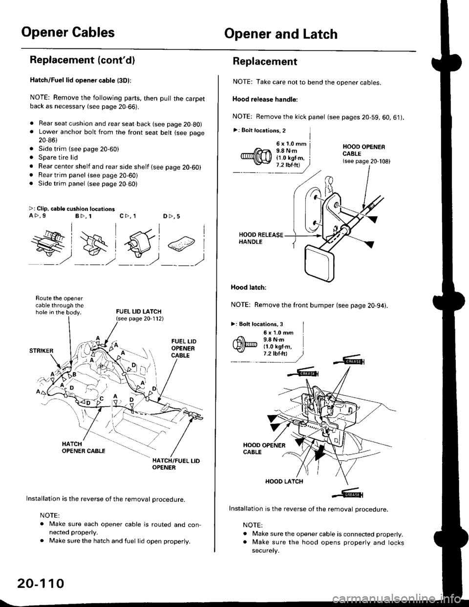
Replacement (cont'dl
Hatch/Fuel lid opener cable l3Dl:
NOTE: Remove the following parts, then pull the carpetback as necessary (see page 20-66).
. Rear seat cushion and rear seat back (see page 20-80). Lower anchor bolt from the front seat belt (see page
20 86)
. Side trim {see page 20-60). Spare tire lid
. Rear center shelf and rear side shelf {see page 20-60). Rear trim panel (see page 20-60). Side trim panel (see page 20,60)
>: Clip, cable cushion locationsa>.9B>, 1c>, 1D >,5
W#)
FUEL LID LATCH
#,
Route the openercable through thehole in the body.
HATCH/FUEL LIOOPENER
Installation is the reverse of the removal procedure.
NOTE:
. Make sure each opener cable is routed and con-nected properly.
. Make sure the hatch and fuel lid open properly.
page 20-112)
20-110
6x1.0mm j9.8Nm{1.0 kgf.m, i
Replacement
NOTE: Take care not to bend the opener cables.
Hood release handle:
NOTE: Remove the kick panel (see pages 20-59, 60.61).
>: Bolt locations, 2 ]I
HOOO OPENERCABLE(see page 20-108)
Hood latch:
NOTE: Remove the front bumper (see page 20-94).
>: Eolt locations, 3 I6 x '1.0 mm9.8 N.m11.0 kgf.m,
Installation is the reverse of the removal procedure.
NOTE:
. Make sure the opener cable is connected properly.. Make sure the hood opens properly and locks
securely.
Page 1345 of 2189

Rear Window Wiper
Arm and MotorWasher Reservoir
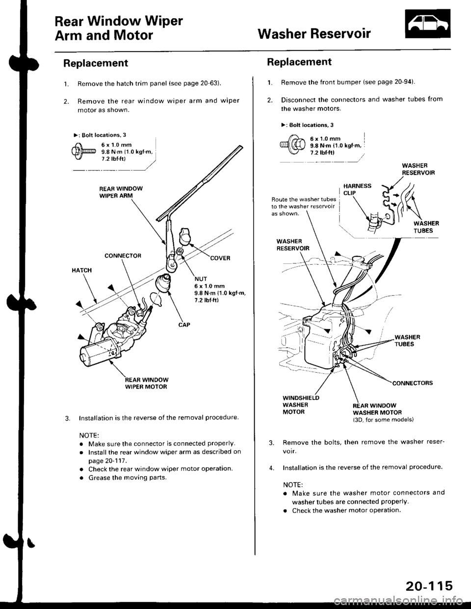
Replacement
't.
2.
Remove the hatch trim panel (see page 20 63).
Remove the rear window wiper arm and wiper
motor as shown.
Installation is the reverse of the removal procedure
NOTE:
. Make sure the connector is connected properly
.Install the rear window wiper arm as described on
page 20-117.
. Check the rear window wiper motor operation.
. Grease the moving parts.
3.
NUT6x1.0mm9.8 N.m 11.0 kgf.m,7.2 tbf.ft)
WIPER MOTOR
L
2.
Replacement
Remove the front bumper (see page 20-94).
Disconnect the connectors and washer tubes from
the washer motors.
>: Bolt locations,3
/)^ 6xt.omm
Ql(S) s.e ru.- tt.o ret '".\./ 7 .2 tbf.ft) /
Route the washer tubes10 the washe. reservoir
wtNDowWASHER MOTOR(3D, for some models)
Remove the bolts, then remove the washer reser-
voir.
Installation is the reverse of the removal procedure.
NOTE:
a Make sure the washer motor connectors and
washer tubes are connected properly.
. Check the washer motor operation.
3.
4.
20-115
Page 1364 of 2189
Body ('99 model)
Dashboard
Center Panel Removal and
lnstallation
Bumpers
Front Grille Removal and
lnstallation
Front Air Spoiler Replacement ."'.....
Seats
Front Seat DisassemblY and
ReassemblY 20-138
Front Seat Torsion Bar
Replacement '.'...".'....'... 20-139
Emblems
tnstallation 20-140
20-136
20-136
20-137
Outline of '99 Model Changes
The center Danel removal and installation procedures are different'
The front grille removal and installation procedures are different'
The front air spoiler has been added for some models of 2D'
A height-adjustable driver's seat was added to some models'
Emblems were added for some models ot 2D'
Page 1365 of 2189
DashboardBumpers
I
Center Panel Removal and
Installation
1. Remove the dashboard center lower cover.
2. Remove the screws, then pull out the center panel.
>: Sc.ew locationi,4 >: Clip locationsA >,3B>,4rl
@Y,
UPPER VENT I(NOB
Disconnect the connectors from the heater controlunit and hazard warning switch.
Installation is the reverse of the removal procedure.
NOTE: Make sure the connectors are connectedpropefly.
20-136
Installation is the reverse of the removal procedure.
FRONT BUMPER
a&
Front Grille Removal and
Installation
NOTE: Take care not to scratch the front bumper.
Remove the front bumper. Remove the screws. thenslide the front grille forward by detaching the hooks.
>: Scrow locltion3,6
I
dbp i
Page 1366 of 2189
Front Air SPoiler RePlacement
CAUTION: Put on gloves to protect your hands'
NOTE:
. An assistant is helpful when removing the front bumper'
. Take care not to scratch the front bumper and body'
>: Bolt, screw localions
A >,9 B >,4
s*i@l
BUMPER
lnstallation is the reverse of the removal procedure'
NOTE:
. Make sure the front bumper engages the front
bumper side stiffener on each side securely'
o lf necessary. adjustthe front bumper side stiffener
to obtain the Proper gap.
FRONT AIR SPOILER
20-137
Page 1498 of 2189

Connector ldentification and WireHarness Routing
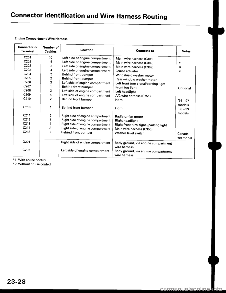
Engine Compartment Wire Harness
conneqtor of
Terminal
Number of
CavitiesLocationConnects toNotes
c201
c202
c202
c203
c204
c205
c206
c207
c208
c209
c210
c210
c211
c212
c213
c214
c215
10
6
2
2
2
1
3
2
1
2
8
Left side of engine companment
Left side of engine companment
Left side of engine companment
Left side of engine compartment
Behind front bumper
Behind front bumper
Left side of engine compartment
Behind front bumper
Left side of engine compartment
Left side of engine companment
Behind front bumper
Behind front bumper
Right side of engine compartment
Right side of engine compartment
Right side of engine compartment
Right side of engine compartment
Behind front bumper
Main wire harness (C308)
Main wire harness (C309)
Main wire harness {C309)Cruise actuator
Windshield washer motor
Rear window washer motor
Left front turn signal/parking lightFront fog light
Left headlight
Ay'C wire harness 1C751)Horn
HOrn
Radiator fan motor
Right headlight
Right front turn signal/parking lightMain wire harness (C355)
Washer level switch
Optional
'96 - 97
models'98 - 99
models
Canada'99 model
G201
G202
Right side of engine compartment
Left side of engine compartment
Body ground, via engine compartmentwire harness
Body ground, via engine compartmentwrre harness*1r With cruise control*2: Without cruise control
23-2A
Page 1637 of 2189

Headlights/Front Turn
Signal/Parking Lights
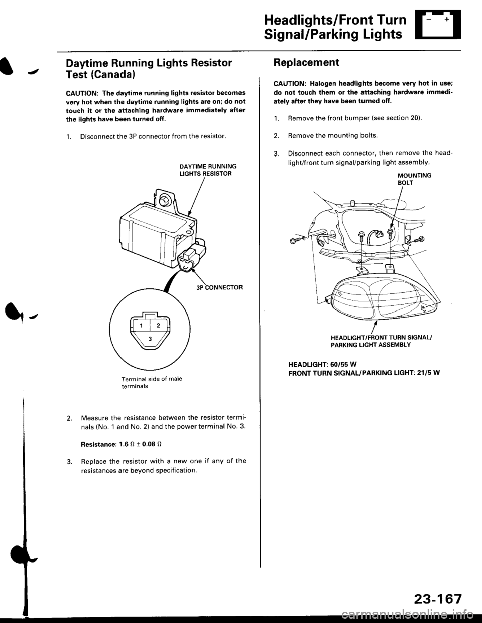
Daytime Running Lights Resistor
Test (Canada)
CAUTION: The daytime running lights resistor becomes
very hot when the daytime running lights are on; do not
touch il or the attaching hardware immediately after
the lights have been iurned off.
1. Disconnect the 3P connector from the resistor.
Terminal side of male
terminals
N4easure the resistance between the resistor termi
nals (No. 1 and No. 2) and the power terminal No. 3.
Resistance: 1.6 O t 0.08 O
Replace the resistor with a new one if any of the
resistances are beyond specification.
It-
Replacement
CAUTION: Halogen headlights b€come very hot in use;
do not touch them or the attaching hardware immedi-
ately after they have been turned off.
1. Remove the front bumper (see section 20).
2. Remove the mounting bolts,
3. Disconnect each connector, then remove the head-
lighVfront turn signal/parking light assembly.
MOUNTINGEOLT
HEADLIGHT/FRONT TUFN SIGNAL/PARKING LIGHT ASSEMBLY
HEADLIGHT: 60/55 W
FRONT TURN SIGNAL/PARKING LIGHT: 21l5 w
23-167
Page 1667 of 2189
Circuit Diagram: '96 - 97 models
HORNRELAY
WHT/GRN
I(H)HoRN
Y
IBLU/REO
I
I
IBtK
I
t-l
G40lG1A2
BATTERY
l-
23-197
Horn Test: '96 - 97 models
1. Remove the front bumper (see section 20).
2. Disconnect the 2P connector from the horn.
Remove the horn.
Test the horn by connecting battery power to one
terminal and grounding the other, lf the horn fails to
sound, replace it.
3.
LOW HORN