2000 HONDA CIVIC Air idle
[x] Cancel search: Air idlePage 291 of 2189
System Description
Vacuum Connections (cont'd)
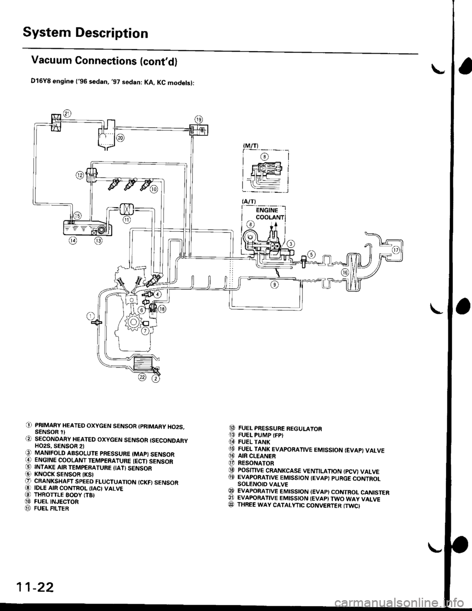
D16Y8 engine ('96 sedan, '97 sedan: KA, KC modelsl:
PRIMARY HEATED OXYGEN SENSOR (PRIMARY HO2S.SENSOR SECONOARY HEATED OXYGEN SENSOR {SECONDARYHO2S, SENSOR 2lMANIFOLD ABSOLUTE PRESSUBE {MAPI SENSORENGINE COOLANT TEMPERATURE {ECTI SENSORINTAKE AIR TEMPERATUFE IIATI SENSORKNOCK SENSOR IKSICRANKSHAFT SPEED FLUCTUATION {CKFI SENSORIDLE AIR CONTROL IIACI VALVETHROTTLE EODY (T8)FUEL INJECTORFUEL FILTER
FUEL PRESSURE REGULATORFUEL PUMP {FPIFUEL TANKFUEL TANK EVAPORATIVE EMISSION IEVAP} VALVEAIR CLEANERRESONATORPOSITIVE CRANKCASE VENTILATION {PCV} VALVEEVAPORATIVE EMISSION IEVAP) PURGE CONTROLSOLENOID VALVEEVAPORATIVE EMISSION IEVAPI CONTROL CANISTEREVAFORATIVE EMISSION IEVAP} TWO WAY VALVETHREE WAY CATALYTIC CONVERTER (TWC'
{M/T}
i@l: F@i
HiiFl
(A/T)
I ENGINE I
I coor-rruri
i@ i+ il/A. nfi |(Or)l /U[ |)l#t,/,6
0)
t;
-l
@
!o,(t
@@@
@@@(9
@@@(D
@A)@
11-22
Page 293 of 2189
![HONDA CIVIC 2000 6.G Workshop Manual System Description
Vacuum Connections (contdl
D16Y8 engine l99 - 00 modetsl:
(]-i PAIMARY HEATEO OXYGEN SENSOR {PRIMARY HO2S,SENSOR 1)..2r SECONOARY HEATEO OXycEN SENSOB ISECONDARYHO2S, SENSOR 2li3) HONDA CIVIC 2000 6.G Workshop Manual System Description
Vacuum Connections (contdl
D16Y8 engine l99 - 00 modetsl:
(]-i PAIMARY HEATEO OXYGEN SENSOR {PRIMARY HO2S,SENSOR 1)..2r SECONOARY HEATEO OXycEN SENSOB ISECONDARYHO2S, SENSOR 2li3)](/manual-img/13/6068/w960_6068-292.png)
System Description
Vacuum Connections (cont'dl
D16Y8 engine l'99 - 00 modetsl:
(]-i PAIMARY HEATEO OXYGEN SENSOR {PRIMARY HO2S,SENSOR 1)..2r SECONOARY HEATEO OXycEN SENSOB ISECONDARYHO2S, SENSOR 2li3) MANIFOLD ABSOLUTE PBESSURE {MAPI SENSORO ENGINE cooLANT TEMPERATURE (ECTI sENsoR(5) INTAKE AIR TEMPERATURE {IAT} sENsoRG] KNOCK SENSOR IKSI?r CRANKSHAFT SPEEo FLUCTUATTON {CKF) SENSOR.O IDLE AIR coNTRoL {IAc)vALvEi-9] THROTTLE BOOY {TB)(O FUEL INJECToRI]'i FUEL FILTER.O FUEL PRESSURE REGULAToR[t FUEL PUMP {FPl.D FUEL TANKil' AIR CLEANERTD RESONATORO FUEL TNJEC oN AtR tFtA) coNTRoL vAt_vE.19 POSITIVE CRANKCASE VENTILATION {PCVI VALVE
.19) EVAPORATIVE EMIssIoN {EVAP) PURGE coNTBoLSOLENOID VALVE€g PURGE JorNTtj EVApoRATtvE EMtsstoN {Evap} coNTRoL cANtsTERC4 EVAPONANVE EMISSION (EVAP) BYPASS SOLENOIDVALVE
?3 EVAPORATIVE EMISSION {EVAP} CONTROL CANISTERFILTERA4 EVAPoBATIVE EMIssIoN (EVAP) coNTRoL CANISTERVENT SHUT VALVEC! FUEL TANK PRESSURE sENsoREO EVAPOBATIVE EMISSION (EVAP) TWO WAY VALVEe? oNBoARD REFUELtiIG vApoR REcovERy {oRvR} VENTSHUT VALVE@ oNBoARD REFUELTNG vapoR REcovERy (oRvR) vapoRRECIRCULATION VALVEiP THREE WAY CATAI.YTIC CONVEBTER {TWCI
'- *o'*- -
COOLANT
]L
nrl
L
ii8'x'", *
--j IIM TTI ^n 14 [l(2i)-fr l-1ry|
11-24
Page 294 of 2189
|-
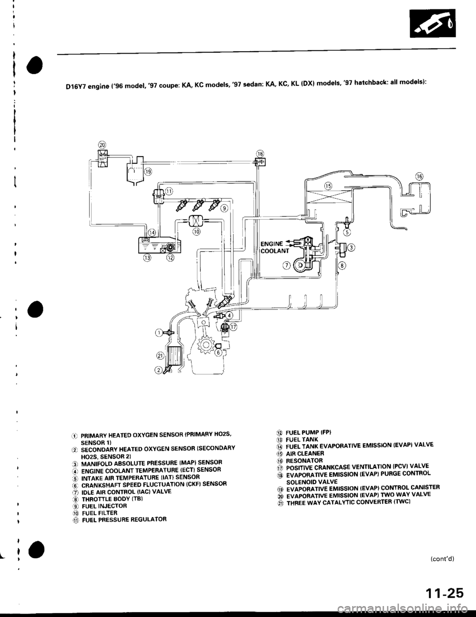
DI6YTengine('96mode|.,97coupe:KA,Kcmode|s,,97sedan:KA,KC,KL{Dx}modets,'gThatchback:a||models}:
COOLANT
o
l)
r.-.
.t)
a:!)
o-o
aroa1t
PRIMARY HEATED OXYGEN SENSOR (PRIMARY HOzS,
SENSOR 1)SECONDARY HEATED OXYGEN SENSOR {SECONDARY
HOzS, SENSOR 2)
MANIFOLD AESOI-UTE PRESSURE IMAP) SENSOR
ENGINE COOLANT TEMPERATURE IECT) SENSOR
INTAKE AIR TEMPERATURE (IAT} SENSOR
CRANKSHAFT SPEED FLUCTUATION (CKF) SENSOR
IDLE AIR CONTROL (IACI VALVE
THROTTLE BOOY (TB)
FUEL INJECTORFUEL FILTERFUEL PRESSURE REGULATOR
FUEL PUMP IFPIFUEL TANKFUEL TANK EVAPORATIVE EMISSION (EVAPI VALVE
AIR CLEANERRESONATORPOSITIVE CRANKCASE VENTILTATION IPCVI VALVE
EVAPORATIVE EMISSION (EVAP} PURGE CONTROL
SOLENOID VALVEEVAPORATIVE EMISSION (EVAP) CONTROL CANISTER
EVAPORATIVE EMISSION IEVAPI TWO WAY VALVE
THREE WAY CATALYTIC CONVERTER (TWCI
[3)@ao(o
a@
(0
@)
(cont'd)
11-25
Page 297 of 2189

I
a
System Description
Vacuum Connections (cont'd)
816A2 engine:
@ EvApoRATtvE EMtsstoN tEvAp) puRGE coNTRoLSOLENOID VALVE@ PURGE JoINT€t EvApoRATtvE EMtsstoN (EVApt coNTRoL caNtsTERQA EVAPORATIVE EMISSION (EVAP) BYPASS SOLENOIDVALVE
@ EVApoRATtvE EMtsstoN lEvApl coNTRoL caNtsrERFILTER@ EvApoRATtvE EMtsstoN {EvApt coNrRoL cANtsrERVENT SHUT VALVE@ FUEL TANK PRESSURE sENsoRGI EVAPORATIVE EMISSION (EVAP} TWO WAY VALVE@ ONBOARD REFUETING VAPOR RECOVERY {ORVR} VENTSHUT VALVE@ oNBoAnD REFUELING vApoR REcovERy (oRvRl vApoR. RECIRCULATION VALVE(c} THREE WAY CATALYTIC CONVERTER {TWCI
(' PRIMARY HEATED OXYGEN SENSOR IPRIMARY HO2S.SENSOR 1l.?) SECONDARY HEATED OXYGEN SENSOR {SECONDARYHO2S, SENSOR 2)13] MANIFOLD ABSoLUTE PRESSURE (MAP) sENsoBi' ENGINE COOLANT TEMPERATURE IECT) SENSORO INTAKE AIR TEMPERATURE ITATI SENSORi6l KNOCK SENSOR {KS}O oRANKSHAFT SPEED FLUCTUATIoN {cKF} sENsoR@ IDLE AIR coNTRoL (IAc} VALVE€) THRoTTLE BoDy trB|(D FUEL INJECToRO FUEL PULSATIoN DAMPER[D FUEL FILTER@ FUEL PRESSURE REGULAToR!I FUEL PUMP IFP)f,' FUEL TANK(iD ArR CLEANERt' RESONAToR'.1]i POSITIVE cRANKcAsE VENTILATIoN {Pcv} VALVE
11-28
Page 353 of 2189
Troubleshooting
Troubleshooting Procedures (cont,dl
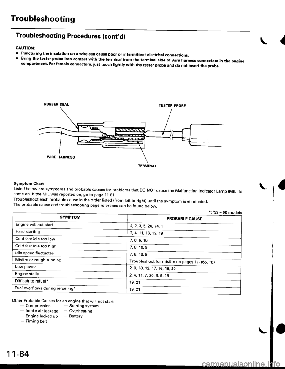
CAUTION:
. Punqturing ihe insulation on a wirs can cause poor or intermiftent electricar connections.I Bring the test€r probe into contacl with the terminatlrom the terminal side of wire harnesg conncctors in the gngin€compartment. For temale connectors, iust touch lightly with the tester probe and do not inse.t the probe.
\I
RUBBER SEAL
Other Probable Causes for an engine that will not start:- Compression- Starting system- lntake air leakage - Overheating- Engine locked up - Battery- Timing belt
TESTER PROBE
Symptom Chart
Listed below are symptoms and probable causes for problems that Do NoT cause the Malfunction indicator Lamp (MlL) tocome on. lfthe MIL was reported on, go to page 11_81.Troubleshoot each probabre cause in the order risted (from reft to right) untir the symptom is eriminated.The probable cause and troubleshooting page reference can be found berow.
L
*: '99 - 00 models
TERMINAL
SYMPTOMPROBABLE CAUSE
4,2,3, 5,20, 14, 1
2, 4, 11, 16, 13, 't9
?, s^6. 16
1,8,10.9
Engine will not sta rt
Hard starting
Cold fast idle too low
Cold fast idle too high
ldle speed fluctuates7,8, 10.9
Troubleshoot for misfire on pages l1-166, 167Misfire or rough running
LOW power
E"g|* "t"lb
2,9, 10, 12, 11, 16, 't8,20
2,4,11,7,20,8,5,15
't9, 21
1r, ,1
Difficult to refuel*
Fuel overflows during refueling*
11-84
Page 355 of 2189
Troubleshooting
Troubleshooting Procedures (cont,dl
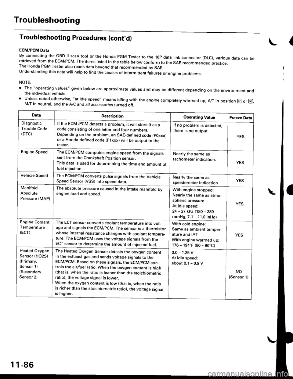
ECM/PCM Data
By connecting the OBD ll scan tool or the Honda pGM Tester to the l6p data link connector (DLC), various data can beretrieved from the EcM/PcM. The items Iisted in the table below conform to the sAE recommended practice.The Honda PGM Tester also reads data beyond that recommended bv SAE.understanding this data wil help to find the causes of intermittent fairures or engine probrems,
NOTE:
' The "operating values" given below are approximate values and may be different depending on the environment andthe individual vehicle.. Unless noted otherwise, "at idle speed,, means idling with the engine completely warmed up, Ay'T in position @ or E],M/T in neutral, and the Ay'C and all accessories turned off.
(
DataDescriptionOperating ValueFreeze Data
Diagnostic
Trouble Code(DTC)
lf the ECM /PCM detects a problem, it will store it as acode consisting of one letter and four numbers.Depending on the problem, an SAE-defined code (poxxx)or a Honda-defined code (Plxxx) will be outDut to therester.
lf no problem is detected,
there is no output.
YES
Engine SpeedThe ECM/PCM computes engine speed from the signalssent from the Crankshaft Position sensor.This data is used for determining the time and amount offuel injection,
Nearly the same as
tachometer indication.YES
Vehicle SpeedThe ECM/PCM converts pulse signals from the VehicleSpeed Sensor (VSS) into speed data.Nearly the same as
speedometer indicationYES
Manifold
Absolute
Pressure {MAP)
The absolute pressure caused in the intake manifold bvengine load and speed.With engine stopped:
Nearly the same as atmo-
spheflc pressure
At idle speed:
24 - 31 kPa (180 - 280
mmHg, 7.1 - 11.0 inHg)
YES
Engine Coolant
Temperature
(ECT)
The ECT sensor converts coolant temperature into volt_age and signals the ECM/PCM. The sensor is a thermistorwhose internal resistance changes with coolant temDera_ture. The ECM/PCM uses the voltage signals from theECT sensor to determine the amount of iniected fuel.
With cold engine:
Same as ambient temper,
ature and IAT
With engine warmed up:
176 - 194.F (80 - 90.C)
YES
Heated Oxygen
Sensor {HO2S)(Primary,
Sensor 1)(Secondary
Sensor 2)
The Heated Oxygen Sensor detects the oxygen contentin the exhaust gas and sends voltage signals to theECI\4/PCM. Based on these signats, the ECM/pCM con_trols the airlfuel ratio. When the oxygen content is high(that is, when the ratio is leaner than the stoichiometricratio), the voltage signal is lower.When the oxygen content is low (that is, when the ratiois richer than the stoichiometric ratio), the voltage signalis higher.
0.0 - 1.25 V
At idle speed:
about 0.1 - 0.9 V
NO(Sensor 1)
1 1-86
Page 356 of 2189
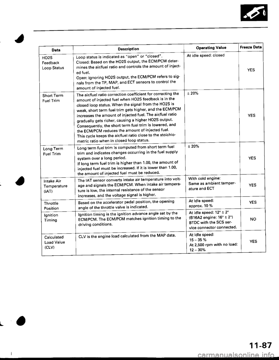
DataDescriotion
Loop status is indicated as "open" or "closed"'
Closed: Based on the HO2S output, the ECM/PCM deter-
mines the airlfuel ratio and controls the amount of inject-
ed fuel.
Open: lgnoring HO2S output, the ECM/PCM refers to sig-
nals from the TP, MAP, and ECT sensors to control the
amount of injected fuel.
The air/fuel ratio correction coefficient for correcting the
amount ot injected fuel when H02S feedback is in the
closed loop status When the signal from the HO2S is
weak, short term fuel trim gets higher, and the ECM/PCM
increases the amount of injected fuel The airlfuel ratio
gradually gets richer, causing a higher HO2S output
Consequently, the short term fuel trim is lowered, and
the ECMiPCM reduces the amount of injected fuel
This cvcle keeps the airlfuel ratio close to the stoichio-
metric ratio when in closed loop status'
Operating ValueF eeza Data
HO2S
Feedback
Loop Status
At idle speed: closed
YES
Short Term
Fuel Trim
! 20%
YES
Long Term
Fuel Trim
Long term fuel trim is computed from shon term fuel
trim and indicates changes occurring in the fuel supply
svstem over a long Period
lf long term fuel trim is higher than 1.00, the amount of
injecGd fuel must be increased. lf it is lower than 1 00'
the amount of injected fuel must be reduced'
! 20%
YES
lntake Air
Temperature
{IAT)
The IAT sensor converts intake air temperature into volt-
age and signals the ECM/PCM. When intake air tempera-
ture is low, the internal resistance of the sensor
increases. and the voltaqe signal is higher'
With cold engine:
Same as ambient temPer'
ature and ECTYES
At idle speed:
approx. 10 %YESThrottle
Position
Based on the accelerator pedal position, the open'ng
angle of the throttle valve is indicated
lgnition
Timing
lgnition timing is the ignition advance angle set by the
gCV/eCV. tn" gCU/PCM matches ignition timing to the
driving conditions.
CLV is the engine load calculated from the MAP data'
At idle speed: 12'i 2'
(81642 engine: 16" t 2")
BTDC with the SCS ser-
vice connector connected.
NO
Calculated
Load Value
{CLV)
At idle speed:
15-35%
At 2.500 rpm with no load:
12 - 30%
YES
ro
11-87
Page 360 of 2189
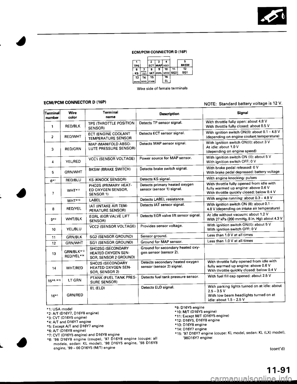
ECM/PCM CONNECTOR D I16P)
Wire side ot female terminals
ECM/PCM CONNECTOR D l16P)NOTE: Standard battery voltage is 12 V
Te.minalnumb€r
Wirecolor
Terminaln!meDor.riptionSignal
RED/BLKTPS (THROTTLE POSITION
SENSOR}
Detects TP sensor signal.With throttle fully open: about 4.8 V
With throttle fully closedl about 0.5 V
REDA/VHTECT {ENGINE COOLANTTEMPERATURE SENSORDetects ECT sensor signalWith ignition switch ON{ll): about 0.1 - 4 8 v
(depending on engine coolant lempe ratu re)
3RED/G RNMAP {MANIFOLD ABSO'LUTE PRESSURE SENSOR}Detects MAP sensor signal.With ignition switch ON(ll): about 3 V
At idle: about 1.0 V
{depending on engine speed)
YEUREDVCCl (SENSOR VOLTAGE)Power source lor MAP sensor.With ignition switch ON (ll): about 5 v
With ignition switch OFF: 0 V
5GRNMHTBKSW {BRAKE SWITCHIDetects brake switch signalWith brake pedal released: 0 v
With brake pedal depressed: baftery voltage
6*?RED/BLUKS {KNOCK SENSOR}Detects KS signal.With engine knocking: Pulses
1
PHO2S (PRIMARY HEAT-ED OXYGEN SENSOR,SENSOR 1)
Detects Primary heated oxygen
sensor (sensor 1l signal
With throttle fullv opened from idle with
Iully warmod up engine: above 0.6 V
With throttle quickly closed: below 0.4 v
LABELDetects LABEL resistanceWith engine r!nning:about 0.3 - 4.9 V
8RED//ELIAT (INTAKE AIR TEM-PERATURE SENSOR)
Detects IAT sensor signal.With ignition switch ON (ll): about 0 1 -
4.8 V {depending on intake air temperature)
9*lWHT/BLKEGRL iEGR VALVE LIFT
SENSOR)
Detects EGR valve lift sensor signalAt idle without vacuum: about'1 2 V
With 27 kPa (2OO mmHg,8 in. Hg): about 4 3 V
10YEUBLUVCC2 (SENSOR VOLTAGE)Provides sensor voltage,With ignition switch ON(ll): about 5 V
With ignition switch OFF:0 V
11GRN/BLKSG2 (SENSOR GROUND}Sensor ground.Less than 1.0 V at alltimes
12G RN,4/1r'HTSG1 (SENSOR GROUND)Ground for MAP sensor.Less than 1.0 V at alltimes
GRN/BLK*1?SHO25G (SECONDARY
HEATED OXYGEN SEN'
SOR, SENSOR 2 GROUND)
Ground for secondary heated oxy-
gen sensor (sensor 2).
14WHT/REDSH02S (SECONDARY
HEATED OXYGEN SEN'soR, sENsoR 2)
Detects secondary heated oxygen
sensor (sensor 2) signal.With throftle fully opened lrom idle with
fully warmed up engine: above 0.6 V
With throttle quickly closed: below 0.4 V
15|3. *15LT GRNPTANK {FUEL TANK PRES.
SURE SENSOR)
Detects fueltank prgssure sensor'With fuelfill caD opened: about 2.5 V
16*1GRN/RED
EL (ELD)Detects ELD signal.With parking lights turned on at idle: about
2.5 - 3.5 VWith low beam headlights turned on at
idle: about 1.5 - 2.5 V
*1: USA model*2r A/T (D16Y7, D16Y8 engine)*3: CVT (D16Y5 engane)*4: A,/T and Dl6Y7 engine*5: Except A/T and D16Y7 engine*6: A"/T (D16Y8 engine)i7: CVT (Dl6Y5 engine) and Dl6Y8 engine*8: .96 D16Y8 engine (coupei,'97 D16Y8 engine
models, sedanr KL model),'98 016Y5 engine,
engine, '99 - 00 D16Y5 (M/T) engine
*9: D16Y5 engine*10: M/T (D16Y5 engine)*11: Except M/T (Dl6Y5 engine)* 12r D16Y5. D16YB engine*13: D16Y8 engine*14: Dl6W engine*15: '97 D16Y7 engine (coupe: KL model, sedan: KL lLX) model),'98D16Y7 engine:(coupe: all'98 D16Y8
(cont'd)
1 1-91