Page 100 of 2189
Engine Removal/lnstailation
Removal (cont'dl
Dl6Y5. DrGYr, D16Y8 enginas:
-1. Remove the mounting bolt and lock bolt, thenremove the P/S pump belt and pump.
MOUNTING BOLT8 x 1.25 mm24 N.m {2.4 kgl.m, 17 tbf.ftl
LOCK BOLT8 x 1.25 mm24 N.m 12.4 kgf.m, 17 lbf.ftl
17. Loosen the idler pulley center nut and adjustingbolt, then remove the air conditioning (A[/C)compressor belt.
IDI.IR PULLEY CENTERNUT10 x 1.25 mma,l N.m {,1.5 kgt.m, 33 lbf.ft)
5-6
(
'18. Remove the ransmission ground cable and hosect8mo.
HOSE CLAMP6 x '1.0 mm
19. Remove the clutch slave cylinder and line/hoseassembty (M/T).
NOTE:
. Do not disconnectthe pipe/hose assembly.. Do not operate the clutch pedal once the slavecylind€r has been removed.o Take care not to bend the line.
6x1,0mm 8x1.2Smm11 N.m {1.1 kgt.m, 2a N.m t2.4 kgf.m,I tbf.ftl 17 tbf.ftl
8 x 1.25 mm2a N'm {2,4 kgt m,17 tbt.ftl
Page 110 of 2189

Engine Removal/lnstallation
Installation (cont'd)
Except CVT:
12 x 1.25 mm64 N.m (6.5 kgd.m,
Tighten the bolts/nut on the left front mount in thenumbered sequence shown {O - @).
(t 12 x 1.25 mm83 N'm (8.5 kgf.m,61 tbt.trl
/+4 N.m 14.5 kgf.m,33 lbt.trl
O 12 r 1.25 mm59 N.m 16.0 kgt.m,43 tbt.rtlSeplace.
5-16
\
7. Perform the following:
. Clean the areas where the driveshaft(s) and theintermediate shaft contact the transmission (dif_ferential) thoroughly with solvent or carburetorcteaner, and dry with compressed air.. Check that the set rings on the ends of the drive_shaft and intermediate shaft click into place.CAUTION: Use new set rings,. Adjust the shift cable (see section 14).. Adjust the throttle cable (see section 11).. Adjust the cruise control cable (see section 23).. Refill the engine with engine oil (see page 8-6).. Refill the transmission with fluid (see section 13,14).
. Refill the radiator with engine coolant (see page10-7).
. Bleed air from the cooling system with the heatervalve open (see page j0-7).
. Clean the battery posts and cable terminals withsandpaper, assemble them, then apply grease toprevent corrosaon.. Inspect for fuel leakage (see section j l).After assembling the fuel line, turn on l) the igni_tion switch (do not operate the starter) so that thefuel pump runs for approximately two secondsand the fuel line pressurizes. Repeat this opera_taon two or three times, then check for fuel leak_age at any point in the fuel line,
Page 116 of 2189

(From page 6'4)
Test the VTEC Solenoid Valve:1. Turn the ignition switch OFF.2. Disconnect the wEC solenoidvalve 1P connector.3. Attach the battery positave
terminal to the VTEC solenoidvalve terminal.4. Start the engine and checkthe oil pressure at enginespeed of 5,000 rpm.
Inspect lhe VTEC solonoid valve
lsee p6ge m).ls the pressure above 390 kPa(4.0 kgtcm'�,57 psi)?
Test the VTEC Pressure Switch:With the battery positive terminalconnected to the VTEC solenoidvalve, measure voltage betweenthe ECM/PCM connector terminal'96 - 98: Cl5,'99 - 00: C10 andbody ground.
ls there battery voltage above5,000 rpm?
T6st the VTEC Solenoid Valvewire:1. Turn the ignition switch OFF.2. Check for continuity betweenthe VTEC solenoid valve 1Pconnector terminal and theECM/PCM connector terminal'96 - 98: A8, '99 00r B'12.
Repair open in the wire betweenthe ECM/PCM ('96 - 98: A8, '99 -
0o: 8l2l and VTEC solenoid v.lv6connoc{or.
Test the VTEC Solenoid Valve
Check for continuity between theVTEC solenoid valve 1P connectorterminal €nd body ground.
ReDair 3hort in the wire betweenthe ECM/FCM ('96 - 98: A.8, '99 -
0O: Bl2l and VTEC aolenoid valveconnectot,
ls there continuity?
Substitute a known-good ECM/PCM and recheck. lf symptom/indication goes away, replacethe original ECM/PCM.
VTEC SOLENOID VALVE1P CONNECTOR
Terminalside ofmale terminal
ECM/PCM CONNECTOR C {31P}
'99 - 00:'96 - 98:
CONNECTOR
'99 - 00:
VTEC SOLENOIDVALVE
ECM/PCM CONNECTORB {25Pt1P CONNECTOR'96 - 98:
VTEC SOLENOIDVALVE
ECM/PCM CONNECTOR
A {32P1
VTS{GRN/YEL)
wire side o{ femaleterminals
wire side oI temaleterminals
VTM
Page 119 of 2189

VTEC Rocker Arms
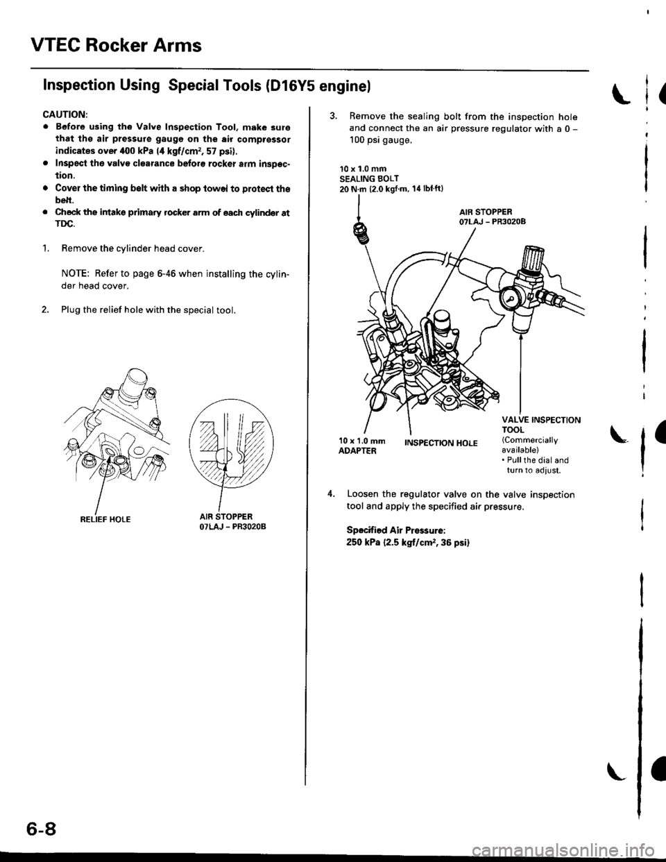
Inspection Using SpecialTools (Dl6Y5 enginel
CAUTION:
. Before using th6 Valve Inspection Tool, make 3ure
that ths air pressure gaugo on the air comptsssor
indicates over iloo kPa 14 kgf/cmr, 57 psi).
. Inspecl th6 valv€ clearance beforo rocker atm insDec"
tion,
'1.
Cover the timing belt with a shop towel to protect tho
belt.
Check ths intakg primaty rocker arm of each cylindqr atTDC.
Remove the cylinder head cover.
NOTE: Refer to page 6-46 when installing the cylin-
der head cover.
Plug the relief hole with the special tool.
YY
OTLAJ - PR3O2OB
(
3, Remove the sealing bolt from the inspection holeand connect the an air pressure regulator with a 0 -
100 psi gauge.
10 x 1.0 mmSEALING BOLT20 N.m {2.0 kgj'm. 14lblft}
l
I
'10 x 1.0 mmADAPTER;NSp€CTTONHOLE (Commercially
available)
l'Pullthe dial andturn to adlust,
Loosen the regulator valve on the valve inspection
tool and apply the specified air pressure.
Spocified Air Pressurei
250 kPa {2.5 kg,t/cm,,36 psi}
o-at
Page 120 of 2189

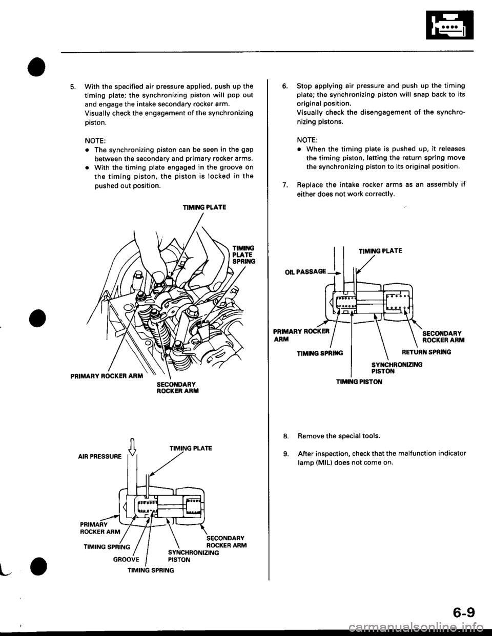
5. With the specified air pressure appli€d, push up the
timing plate; the synchronizing piston will pop out
and engage the intake secondary rocker arm.
Visually check the engagement of the synchronizing
prston.
NOTE;
The synchronizing piston can be seen in the gap
between the secondary and primary rocker arms,
With the timing plate engaged in the groove on
the timing piston, the piston is locked in the
oushed out Dosition.
TIMIiIGPLATESPRIT{C
PRIMARY ROCKER ARM
AIR PRESSURE
GROOVE
SECO DARYROCKER ARM
TIMIT{G PLATE
TIMING SPRING
6-9
6. Stop applying air pressure and push up the timing
plate; the synchronizing piston will snap back to its
original position.
Visually check the disengagement of the synchro-
nizing pistons.
NOTE:
. When the timing plate is pushed up, it releases
the timing piston, letting the return spring move
the synchronizing piston to its original position.
7. Replace the intake rocker arms as an assembly if
either does not work correctly,
TIMING PLATE
oll PASSAGE --!
PRIMARY ROCKER
ARMSECOI{DARYROCKER ARM
TIMII{G SPRII{GRETURI{ SPRING
Remove the spscial tools.
After inspection, check that the malfunction indicator
lamp (MlLl does not come on.
TIMI G PISTOI{
Page 121 of 2189
VTEC Rocker Arms
Inspection Using Special Tools (D16Y8 enginel
CAUTION:
o Before using the Valve Inspection Tool. mak6 surethat the air pressure gauge on the air comprsssor
indicates ovor 400 kPa {4 kgf/cm,, 57 psil.
. Inspect th6 valve clearanco before rockar arm inspec-
tion.
. Cov€r th€ timing belt with a shop towel to protect
the bolt.
. Check tho intake prima.y rockff arm of each cylindel
at TDC.
1.Remove the cylinder head cover.
NOTE: Refer to page 6-46 when installing the cylinder
neao cover,
Plug the relief hole with the specialtool.
OTLAJ - PR3O2OB
I,^ A IAo- tu
3. Remove the sealing bolt from the inspection hole
ancl connect an air pressure regulator with a 0 - 100psi gauge.
l0 x 1.0 mmSEALING EOLT20 N.m (2.0 kgf.m, 14 lbf.ft)
(AIR PRESSUREREGULATOR
{Commerciallyavailable). Pullthe dialandturn to adjust,
Page 122 of 2189
4. Loosen the regulator valve on the valve inspection
tool and apply the specified air pressure.
Specified Air Pressure:
250 kPa {2.5 kgf/cm'�, 36 psil
PRIMARY ROCKERARM
SYNCHRONIZING SYNCHRONIZINGPISTON A PISTON B
Make sure that the intake primary and secondary
rocker arms are mechanically connected by the piston
and that the mid rocker arm does not move when
oushed manuallY.
5.
MID ROCKER SECONDARYARM ROCKER ARM
SECONDARYROCKER ARM
lf any intake mid rocker arm moves independently of
the primary and secondary rocker arms, replace the
rocker arms as a set.t
1.
8.
9.
Remove the special tools.
Use a 10 mm diameter rod to depress each lost
motion assembly through its full movement.
Replace any lost motion assembly that does move
smoothly.
After inspection, check that the MIL does not come
on.
ASSEMBLY
6-11
Page 130 of 2189

Removal
NOTE:
. Replace the timing belt at 105,000 miles (168.000 km)
according to the maintenance schedule (normal con-
ditions/severe conditions).
lf the vehicle is regularly driven in one or more of the
followlng conditions, replace the timing belt at 60.000
miles (U.S.A.) 100,000 km {Canada).
.In very high temperatures (over 110'F.43'C)
. In very low temperatures (under -20'F, -29"C)'
! Turn the crankshaft pulley so the No. 1 piston is at
top dead center (TDC) before removing the belt (see
page 6'21).
. Inspect the water pump before installing the timing
belt {see Page 10-14).
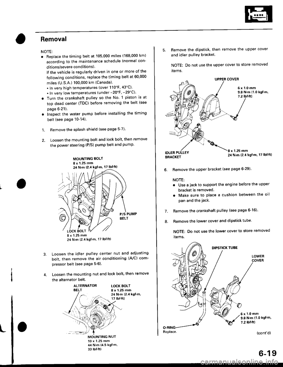
1. Remove the splash shield (see page 5-7).
2. Loosen the mounting bolt and lock bolt. then remove
the power steering (P/S) pump belt and pump
MOUNTING BOLT
8 x 1.25 mm2il N m 12.4 kgl m, 17 lbf'ft)
P/S PUMPBELT
I x 1.25 mm24 N m (2.4 kgf m, 17 lbt ft)
Loosen the idler pulley center nut and adjusting
bolt, then remove the air conditioning (AVC) com-
pressor belt (see Page 5-6).
Loosen the mounting nut and lock bolt, then remove
the alternator belt.
ALTERNATORBELTLOCK BOLTI x 1.25 mm24 N.m 12.4 kgf.m,r? tbI.ft)
3.
MOUNTING NUT10 x 1.25 mm44 N.m 14.5 kgl m,
33 rb{ ft)
5. Remove the dipstick, then remove the upper cover
and idler PulleY bracket
NOTE: Do not use the upper cover to store removed
items.
6x1.0mm9.8 N.m 11.0 kgf.m,7.2
IDLERI x 1.25 mm24 N.m (2.4 kgl.m, 17 lbf'ft)BRACKET
6. Remove the upper bracket {see page 6-29)
NOTE:
. Use a jack to support the engine before the upper
bracket is removed
. Make sure to place a cushion between the oil
pan and the jack.
Remove the crankshaft pulley (see page 6-16).
Remove the lower cover and dipstick tube
NOTE; Do not use the lower cover to store removed
items.
1.
.'.
DIPSTICK TUBE
LOWER
6x1.0mm9.8 N.m (1.0 kgf m,
7.2 rbt.ft)
(cont'd)
6-19
Replace.