Page 1613 of 2189

J
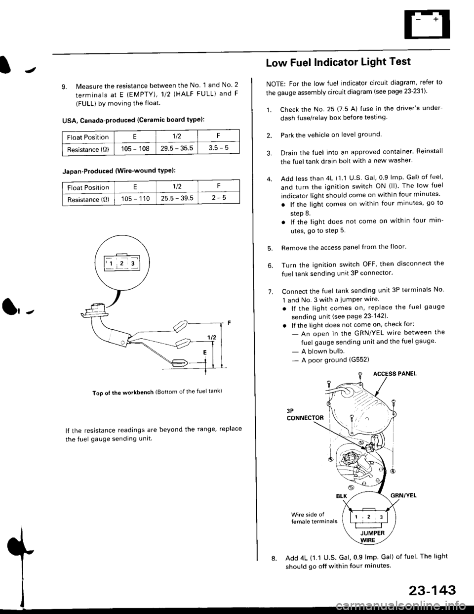
9. lMeasure the resistance between the No 1 and No. 2
terminals at E {EMPTY), 112 \HALF FULL) and F
(FULL) by moving the lloat.
USA, Canada-produced {Ceramic board type):
Too ot lhe workbench (Bottom of the fuel tank)
ll the resistance readings are beyond the range. replace
the fuel gauge sending unit
Float PositionE1t2F
Resistance (0)105 - 10829.5 - 35.53.5-5
Jaoan-Ploduced (Wire-wound typel:
Float PositionE1/2F
Resistance (O)105 - 11025.5 - 39.5
Low Fuel Indicator Light Test
NOTE: For the low fuel indicator circuit diagram, refer to
the gauge assembly circuit diagram (see page 23'2311.
1. Check the No. 25 (7 5 A) luse in the driver's under
dash fuse/relay box before testing
2. Park the vehicle on level ground.
3.
4.
Drain the luel into an approved container. Reinstall
the fueltank drain bolt with a new washer.
Add less than 4L (1 1 U.S Gal, 0.9 lmp Gal) of fuel,
and turn the ignition switch ON (ll). The low fuel
indicator light should come on within four minutes'
. lf the light comes on within four minutes, go to
step 8.
. lf the light does not come on within four min-
utes, go to step 5.
Remove the access panel lrom the Iloor'
Turn the ignition switch OFF, then disconnect the
fuel tank sending unit 3P connector.
Connect the fuel tank sending unit 3P terminals No'
1 and No. 3 with a jumPer wire
. lf the light comes on, replace the fuel gauge
sending unit (see Page 23 1421
. lf the light does not come on, check for:
- An open in the GRN/YEL wire between the
fuel gauge sending unit and the fuel gauge
- A blown bulb.- A poor ground (G552)
6.
1.
female terminals
8. Add 4L {1.1 U.S. Gal, 0 9 lmp Gal) of fuel The light
should go off within four minutes.
23-143
Page 1618 of 2189
Interlock System
Park Pin Switch Test
1, Remove the front console (see section 2Ol.
Disconnect the 4P connector from the park pinswitch.
Check for continuity between the No. 3 and No. 4terminals with:- the shift lever any position other than E, or- the push button pushed in E.There should be continuity.
Check for continuity between the No. 3 and No. 4terminals with the shift lever in E and the push but-ton released. There should be no continuiw. lf nec-essary, replace the park pin switch.
NOTE: Park pin switch 4p connector No. 1 and No.2terminals are lor Ay'T gear position console light.refer to the circuit diagram on page 23-1S0.
23-14A
Page 1623 of 2189

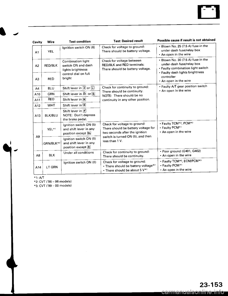
Test conditionTest: Desired resultPossible cause it result is not obtainedCavity
AIYEL
lgnition switch ON (ll)Check for voltage to ground:
There should be banerY voltage.
. Blown No.25 (7.5 A) fuse in the
under dash fuse/relay box
. An open in the wire
A2RED/BLK
Combination light
switch ON and dash
lights brightness
control dial on full
bright
Check for voltage between
RED/BLK and RED terminals:
There should be batterY voltage.
Blown No. 30 {7.5 A) fuse in the
under-dash tuse/relay box
Faulty combination light switch
Faulty dash lights brightness
controller
An open in the wireA3RED
BLUShift lever in P or ICheck for continuity to ground:
There should be continuitY
NOTE: There should be no
continuity in anY other Position.
. Faulty A/T gear Position switch
. An open in the wire
A10GRNShift lever in E or E
A11REDShift lever in E
412WHTShift lever in E
A13BLK/BLU
Shift lever in E
NOTE: Don't depress
the brake pedal.
A9
YEL+ ]lgnition switch ON (ll)
and shift lever in any
position except Pi
Check for voltage to ground:
There should be battery voltage for
two seconds after the ignition
switch is turned ON (ll), and then
less than 'l V.
Faulty TCM*'�, PCM*3
Faulty PCM*r
An open in the wire
GRN/err*'
lgnition switch ON {ll)
and shift lever in anY
position except E
A8BLKUnder all conditionsCheck for continuitv to ground:
There should be continuitY.
. Poor ground (G401, G402)
. An open in the wire
414LT GRN
lgnition switch ON (ll)Check for voltage to ground:
. There should be baftery voltage*'�
. There should be about 5 V*r
Faulty TCM*'�, ECM/PCM*'
Faulty PCM*1
An open in the wire
*2: CVT ('96 - 98 models)*3r CVT ('99 - 00 modelsl
23-153
Page 1624 of 2189
A/T Gear Position Indicator
A/T Gear Position Switch Test
1. Remove the front console (see section 2O).
2. Disconnect the 14P connector from the A/T gear position switch.
3. Check for continuity between the terminals in each switch position according to the table.
' Move the shift lever back and forth without pushing the shift lever at each switch position, and check for continuitywithin the range of free play of the shift lever.' lf there is no continuity within the range of free play, adjust the position of the switch as described on the nextpage.
Terminal side of male terminals
A/T Gear Position Switch
+ 1 : With cruise controlsystem
23-154
Eack - upLight SwitchNeutralPosition Switch
Page 1627 of 2189
(A,4)
A,T GEARPosrfloN swlrcH _ _(Closed h posilon l?l ot [!l )
BLU/BLK -> [h'#f- |COMEINATIONLIGHT SWITCH
V
IREO/GRN
UNDEF.DASH FUSEi RELAY BOX
a
E
YEL
I
A iEi,I,B"'T
vll".i,l
| ,rr.nrorro .orrro, ,*,,
tt-
t(
rffi
|
BEMI\DEB crqcurl
lm
| /t I
tffinEoTsru REDTBLU BLIJ/RED clnculr
-neoieru | ,,-,r.0 J
l, "ulTo
/fP /Itr\
YVI onrveqs I or rtor
l3fifl&''' l5frl'.'
l (3'&T' 8iytr") l
(3&Y fiti'fJ"fl )
BLK BLK
TT
c552 G401
I
. BRAKE FLUIDLEVEL SWITCH. PARKING ERAKEswrTcH (usA)
' CEILING LIGHT. KEYLESS RECE VER CIRCUIT(ln lhe audio unil")
..aorr,rro Y
A
Iu$ut,""'
I3fif'�3#3trr,)-::
DRIVER'SDOOFswtTcHfolosed : Door open )(Open :Doordosed/
STARTERCUT FELAY
a
-
GFNi RED
23-157
Page 1630 of 2189

Integrated Gontrol Unit
Input Test (cont'dl
A8--------.--all
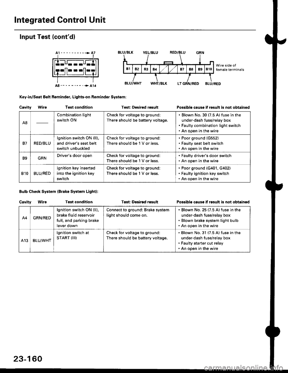
Key-in/Seat Belt R€mind€r, Lights-on Reminder Systom:
Cavity WireTest condhion
Bulb Check System (Brako System Light):
Cavity WireTest condilion
Tost: D€sirod r€guh
T6st: Dosirad result
Possible cause if result is not obtained
Possibls cause if rasuft b not obtainod
A8
Combination light
switch ON
Check for voltage to ground;
There should be battery voltage.
Blown No.30 (7.5 A)fuse in the
under-dash fuse/relay box
Faulty combination light switch
An open in the wire
B7RED/BLU
lgnition switch ON (ll),
and driver's seat belt
switch unbuckled
Check for voltage to ground:
There should be 1 V or less.
Poor ground (G552)
Faulty seat belt switch
An open in the wire
B9GRNDriver's door openCheck for voltage to ground:
There should be 1 V or less.
. Faulty driver's door switch. An open in the wire
Bl0BLU/RED
lgnition key inserted
into the ignition key
switch
Check for voltage to ground:
There should be 1 V or less.
Poor ground (G401. G402)
Faulty ignition key switch
An open in the wire
A4GRN/RED
lgnition switch ON {ll),
brake fluid reservoir
full, and parking brake
tever oown
Connect to ground: Brake system
light should come on.
Blown No.25 (7.5 Alfuse in the
under-dash fuse/relay box
Blown brake system light bulb
An open in the wire
A13BLUA/1r'HT
lgnition switch at
START (III)Check for voltage to ground:
There should be battery voltage.
Blown No.31 (7.5 A) fuse in the
under-dash fuse/relay box
Faulty starter cut relay
An open in the wire
23-160
Page 1632 of 2189
Lighting System
Gomponent Location Index (cont'dl
TURN SIGNAL INDICATOR LIGHTDASH LIGHTS BRIGHTNESSCONTROLLERController Input Test,page 23-119COMBINATION LIGHT SWITCHTest, page 23'165
TURN SIGNAL/HAZARD RELAYInput Test, page 23-'172
HIGH BEAM INOICATOR LIGHT
L ILI LILI LT
rr Lr rJ|r LJ Lr Lr rr !.r rr Lr rr I l-nnr1nr1r1r1r1|-1nn L JJ
r1 n11t'1n Ttr1 r1 - 11 t-1Tt-l T1r-t L.l Lt r-t r-t LJ ! ! LJ LJ ! LJ !J r-l
23-162
Page 1635 of 2189

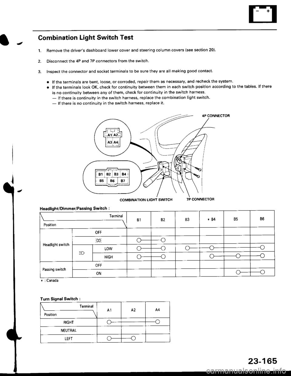
Combination Light Switch Test
1.Remove the driver's dashboard lower cover and steering column covers (see section 20)
Disconnect the 4P and 7P connectors from the switch.
Inspect the connector and socket terminals to be sure they are all making good contact
. lf the terminals are bent, loose. or corroded, repair them as necessary, and recheck the system.
. lf theterminals look OK, check for continuity between them ineach switch position according tothetables lfthere
is no continuity between any of them. check for continuity in the switch harness
- lf there is continuity in the switch harness. replace the combination light switch
- lf there is no continuity in the switch harness, replace it.
2.
4P CONNECTOR
COMBINATION LIGHT SWITCH7P CONNECTOR
HsadlighUDimmer/Passing Switch :
* : Canada
rrr r-l
l(rr mf ItffiTI A3 A11l
Terminal
Position
B182B3*84B586
Headlight switch
OFF
o---o
LOWo---oo-----o
HIGHo-----oo---o
Passing switchOFF
ONo-----o
Turn Signal Switch :
Teminal
;',*;----__\A1A2A4
RIGHToo
NEUTRAL
LEFToo
23-165