2000 HONDA CIVIC Ac dash connector
[x] Cancel search: Ac dash connectorPage 1813 of 2189
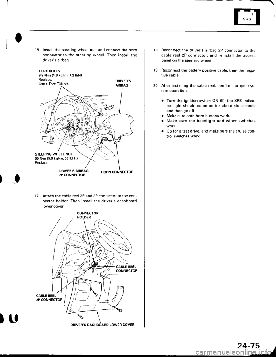
16. Install the steering wheel nut, and connect the horn
connector to the steering wheel. Then install the
driver's airbag.
TORX SOLTS9.8 N m 11.0 kgf m, 7.2 lbtftlReplace.Use a Torx T30 bit.
STEERING WHEEL NUT50 N.m 15.0 kgf.m,36lblft)Replace.
DRIVEB'SAIRBAG
DRIVER'S2P CONNECTOBHORN CONNECTOB
I
17.Attach the cable reel 2P and 3P connector to the con-
nector holder. Then install the driver's dashboard
lower cover.
)UDRIVER'S DASHBOARD LOWER COVER
24-75
18. Reconnect the driver's airbag 2P connector to the
cable reel 2P connector. and reinstall the accesspanel on the steering wheel.
19. Reconnect the battery positive cable, then the nega-
tive cable.
20. After installing the cable reel, confirm proper sys-
tem operation:
Turn the ignition switch ON (ll); the SRS indica-
tor light should come on for about six seconds
and then go off.
Make sure both horn buttons work.
Make sure the headlight and wiper switches
Go for a test drive, and make sure the cruise con
trol switches work.
a
a
Page 1819 of 2189
How To Use This Manual
Circuit Schematics
oa
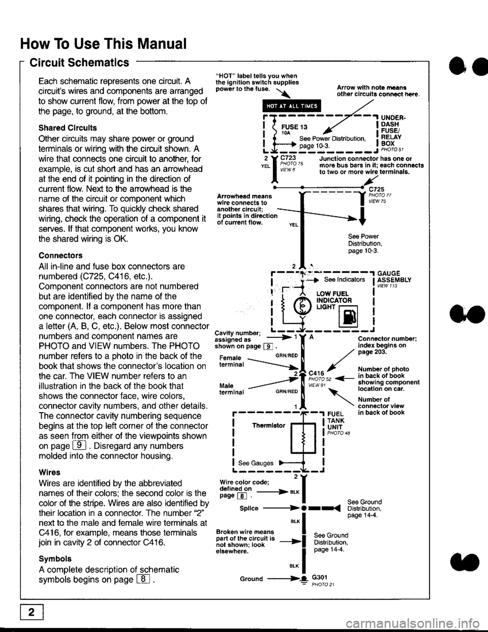
Each schematic represents one circult. A
circuit's wires and components are arranged
to show current flow, from power at the top of
the page, to ground, at the bottom.
Shared Circuits
Other circuits may share power or ground
terminals or wiring with the circuit shown. A
wire that connects one circuit to another, for
example, is cut short and has an arrowhead
at the end of it pointing in the direction of
current flow. Nelit to the anowhead is the
name o{ the circuil or comoonent which
shares that wiring. To quickly check shared
wiring, check the operation of a component it
serves. lf that component works, you know
the shared wiring is OK.
Connectors
All in-line and fuse box connectors are
numbered (C725, C416, etc.).
Component connectors are not numbered
but are identiJied by the name of the
component. lf a componenl has more than
one connector, each connector is assigned
a letter (A, B, C, etc.). Below most connector
numbers and comDonent names are
PHOTO and VIEW numbers. The PHOTO
number refers to a Dhoto in the back of the
book that shows lhe conneclor's location on
the car. The VIEW number refers to an
illustration in the back of the book that
shows the connector face, wire colors,
connector cavity numbers, and other details.
The connector cavity numbering sequence
begins at the top left corner oJ the connector
as seen from either of the viewooints shown
on page ffl . Disregard any numbers
molded into the connector housino.
Wires
Wires are identilied by the abbreviated
names of their colors; the second color rs the
color of the stripe. Wires are also identified by
their location in a connector. The number '2"
next to the male and female wire terminals at
C416, for example, means those terminals
join in cavity 2 of connector C416.
Symbols
A complete description of schematic
symbols begins on page | 8
"HOT" label tells you whenthe ignition switch suppliespower to the fuse. \
Artowhead meanswire connects toanother circuit;
Arrow with note rErngother circuils conncct h€re.
it .a
llu":: ^,{ ii t See Power Distribution, .I t----t oaqe tO-3. IL*--:--------J2 Y C723 Junction connectorYEL I Pao'o'8 more bus bars in it;
I - " " to two or more wire
l,/
-t>?
See PowerDistribution,page 10-3.
UNDER.DASHFUSE/RELAYBOX
has one oleach connactgterminala.
it ooints in directionof current flow.
TheImletor
t_I
Cavity number; L ---
Jiili'iJi!--' -----> '
shoin on page S .
Maleterminal
L?*?l?,-
"'"'I
c725
vlEUt/ 75
Connector number;index begins onpage 203.
Number ot photoin back ol bookshowing componentlocation on cat.
Number ofconneclor viewin back of book
7
GBN/FEO
See Ground
Soe Indicators I ASSEMBLY
:-------J
LOW FUELINDICATOFLIGHT r-l
EI
A
"o'r"/PHOTO 52 <-
\
FUELTANKUNIT
Splice ---------) O rr
".* I Page 14'4'
IBroken wire means | --^ -
iar";J.'It,;,rJ;ii; -----i Bffi,Bili*l
elsewhere. I 0a0e tn-a
IBrK Icround --->lL c301: ptioro 21
Page 1834 of 2189
![HONDA CIVIC 2000 6.G Workshop Manual Fuse/Relay Information
- Under-dash Fuse/Relay Box
Front View
c712(To moonroof wire harness)
. : Canadai : Not UsedO : C926 loprion (+B)l
@ : C927 loption (dash lights)]
O : C928 [Option (ACC]I
@ : C9 HONDA CIVIC 2000 6.G Workshop Manual Fuse/Relay Information
- Under-dash Fuse/Relay Box
Front View
c712(To moonroof wire harness)
. : Canadai : Not UsedO : C926 loprion (+B)l
@ : C927 loption (dash lights)]
O : C928 [Option (ACC]I
@ : C9](/manual-img/13/6068/w960_6068-1833.png)
Fuse/Relay Information
- Under-dash Fuse/Relay Box
Front View
c712(To moonroof wire harness)
. : Canadai : Not UsedO : C926 loprion (+B)l
@ : C927 loption (dash lights)]
O : C928 [Option (ACC]I
@ : C929 loption (lc2)l
Rear View
css2
c421(To main wire harness)
c801CI-o SRS main harness)
c501(To dashboard wire harness)
^ : Not used ('96-'97 models)
c913(To ignition switch)
INTEGRATEDCONTROL UNITCONNECTOR A
c419Oo main wire harness)
REAR WINDOWDEFOGGER RELAY
TURN SIGNAUHAZARD RELAY
c423(To main wire harness)
co
c422(To main wire harness)
POWERwtNDowRELAY
c551flo lloor wire harness)c439 f96.'97 MODELSand ALL GX MOOELS)(To main wire harness)
T1 T-t T"l T"t r-r r-'l T1 F n r-l r-l r'123 24 25 26 27 28 29 30 31 32 33I-J I.J I.J IJ IJ IJ LJ IJ IJ I.J I.J I-I
r"1 r-t r-t T-l r"l r-r Fl r:1 n rJ n -12 13 14 t5 16 17 t8 19 2A 2t 22LI I.J L! LI tJ LJ (J LI IJ IJ T-I I.J
n r:l rj.l |-l T"l Tl r:t n r-l |;.l r-r r-l1 2 3 4 5 6 7 I 9 10 11LI LI IJ LJ LJ I,J T-I I.J TJ IJ I.-I tJ
c420(To main wire harness)
6
(To floor wire harness)
Page 1840 of 2189

Ground-to-Components I ndex
f.,lONOTE: All ground wires are BLK unless otherwise noted.
GroundPageComponents or Circuit Grounded
Battery (BLKYEL)
Steering pump bracket
t+-rg ITransmission housing
l
G101
(-1)
G101
(-2)
14-2
and
14-3
ano
14-1
Powertrain or engine control module (PG1 and pG2 are BLK: LG1 and LG2 are
BRN/BLK), EGR control solenoid valve (CW, EGR valve and lift sensor (Dt6yS enginewith M,/T), Engine coolant temperature switch, pGM-Fl main relay, power steeringpressure switch (USA), Primary HO2S (D16Y5 engine with l\/,/T), Vehicle speed sensor,VTEC pressure switch (D16Y5/D16Y8 engines), CKF sensor (BRN/BLK), Transmission
control module (CYf) (Pc1 is BLK: LG1 is BRN/BLK)
Shielding betvveen the PCM or ECM and these components (all have BRN/BLK wires):
CKF sensor, TDC/CKP/CYP sensor. Primary and secondary heated oxygen sensors.
Knock sensor (CWDl6YB engine), Mainshaft speed sensor (AiT except CVT),
I Countershaft speed sensor (A/T except CVf)
Shielding between the TCM and these components (CVT) (all have BRN/BLK wires):
Drive pulley speed sensor, Driven pulley speed sensor, Secondary gear shaft
speed sensor
Powertrain or engine control module (PG1 and pG2 are BLK; LG1 and LGz are
BRN/BLK), EGR control solenoid valve (D16Y5 engine), EGR valve (Dt685), Engine
coolant temperature switch, Fuel pressure regulator shut-off solenoid valve (D1685),
PGM-FI main relay, Power steering pressure switch (USA), Vehicle speed sensor, VTECpressure switch (All except D16Y7 engine), CKF sensor (A
except 81642) (BRN/BLK)
Shielding between the PCM or ECM and these components (all have BRN/BLK wires):
CKF sensor, TDC/CKP/CYP sensor, Primary and secondary heated oxygen sensors,
Knock sensor (All except D16Y7 engine), i/ainshaft speed sensor (Arf except CW),
Countershaft speed sensor (A,/T except CVf), Drive pulley speed sensor (CW), Drivenpulley speed sensor (CVT), Secondary gear shaft speed sensor (CVf)
I Badiator fan motor, Right front parking/turn signat tight, Right headtight
G20214-4I Cruise control actuator, Left front parking/turn signal lights, Left headlight, Rear window
I washer motor, Windshield washer motor, Washer fluid level switch (,99-'00 Canada)
G401| +-o
and
14-7
Accessory power socket, Brake fluid level switch, Clutch interlock switch (M/T), Clutchswitch (lillT with cruise/D16Y5 engine with MfD, Combination wiper switch (Z wires),
Cruise control main switch, Cruise control unit, Dash lights brightness controller, Data
link connector, Daytime running lights control unit (Canada), Gauge assembly, Horn('96-'97 models), Integrated control unit, Interlock control unit (ArI), Keyless door lock
control unit ('99-'00 models with keyless), Moonroof close and open relays, Moonroof
switch, Park pin switch (A/r), Power window relay, Rear window defogger relay, Rear
window defogger switch ('96-'98 models), Steering lock, Stereo radio tuner (,96-,98
USA: LX, EX, and HX), Turn signal/hazard relay, Windshield wiper motor.....plus
everything grounded through G402
6-6
Page 1852 of 2189
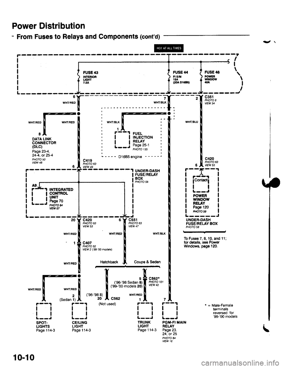
Power Distribution
- From Fuses to Relays and Components (cont'd)
-",JX-
I
I
\FUSE '3n{fEtbRUC|{T7.'.4
FUSE 44FI EA'!aacoa Dr6lc)
FUSE il8POUGNtvtl|Do{taoa
c351
c420PHOTO 63
I-.:CrJ
WIIT/ELX
1
I
I
I
I
FUELINJECTIONRELAYPage 25-1PHOTO 135
DATA LINKCONNECTOR(DLc)
Page 23-4,24-4, ot 25-4PHOfO 5001685 engine -
c419PHOTO 63
UNDER.DASHFUSE/RELAYBOXPHO|Q 5A
POWEBw]tDowNELAYPagE 120H$fa8
L-- ----- --20
wlIT/RED
-t
c420 6PHO|O 63vtEw 53
WHT/FEO
c407PHOTO 52Y|EW 2 ( 9& 00 modsrs)
c5s'rPHO|O 63
L-----JU DEN.DASHFUSE/RELAY BOXPHOfO 58
To Fuses 7, 8, 1 0, and I 1 ;tor deiails, s8€ PowerVYindotts, pa$ 120.
HatchbackCoup€ & S€dan
WHT/FED
(Sedan 1)
(e6-
101
,,, tr:::--*''.:lltut
(Not used)
i--l
tlL--J
TRUNKLIGHTPage 114-3
tl
tl
SPOT.LIGHTSPage 114-3
tl
tl
CEILINGLIGHTPage 114-3
* = Male-Femaleterminalsreversed for'99-'00 models
7A
tl
tl
PGM-FI MAINRELAYPage 23.24, ot 25
vtLw 18
I
I
PGM-FIRELAYPage 2324, ot 22
vtLw 18
i-,-x;-l
icontac{i
tlINTEGNATED
l__i!ffi*
10-10
Page 1855 of 2189
ie----1
\{
i____J
WIIT/FED
FUSE 54OPNOI404
c351
vtEw 34
c419
FUSE 52HOAT. ST(IP LT154
c352
vlEw2/
FUSE 53NAZABO
c352
vtEw 27
c4't 1
UNDER-HOODFUSE/RELAYgox
15
_",":IWH'/BLK
(Not (Not 7Used) Used)
UNDER-DASHFUSE/RELAY BOXPHOTA 58
c419 C926110!0,63 oPTtoNCONNECTOBPHOTO 62
WHT/GRN
{with CruiseControl 4)
WHT
'9&'98 modelspre'wked toracteEsorysacurity system
""'l
o
;l10
vtEw 6a
cs16
'99'0O modelspre-wired foraccessorysecurfy system
SECURIrySYSTEMCONNECTOR(oPTroN)Page 133-4
ll
tl
BRAKESWITCHPages 23-4 , 24 4 ,25-4, 34-1, 39,39-4, 39-8, 39-12,44-2,110-15,110-16, 110 17,'138, and 138-1
ll
ll
HAZARDWARNINGswrTcHPage 110'6or 110-8vtEw 32
,rr rrRt3,:i]L-
SECURITYSYSTEMCONNECTOR(oPTlON)Page 133-4
r----=-:'l
I Uoll UonEcI I
tlL------JHORN BELAYPage 40, 40-1,ot 40-2
PHOTO 58 (96 97 models)PHOIo 129 (98 mode)
c447
wEw 5a
sEcuRrwSYSTEMCONNECTOR(oPTroN)Page 133
10-13
Page 1864 of 2189
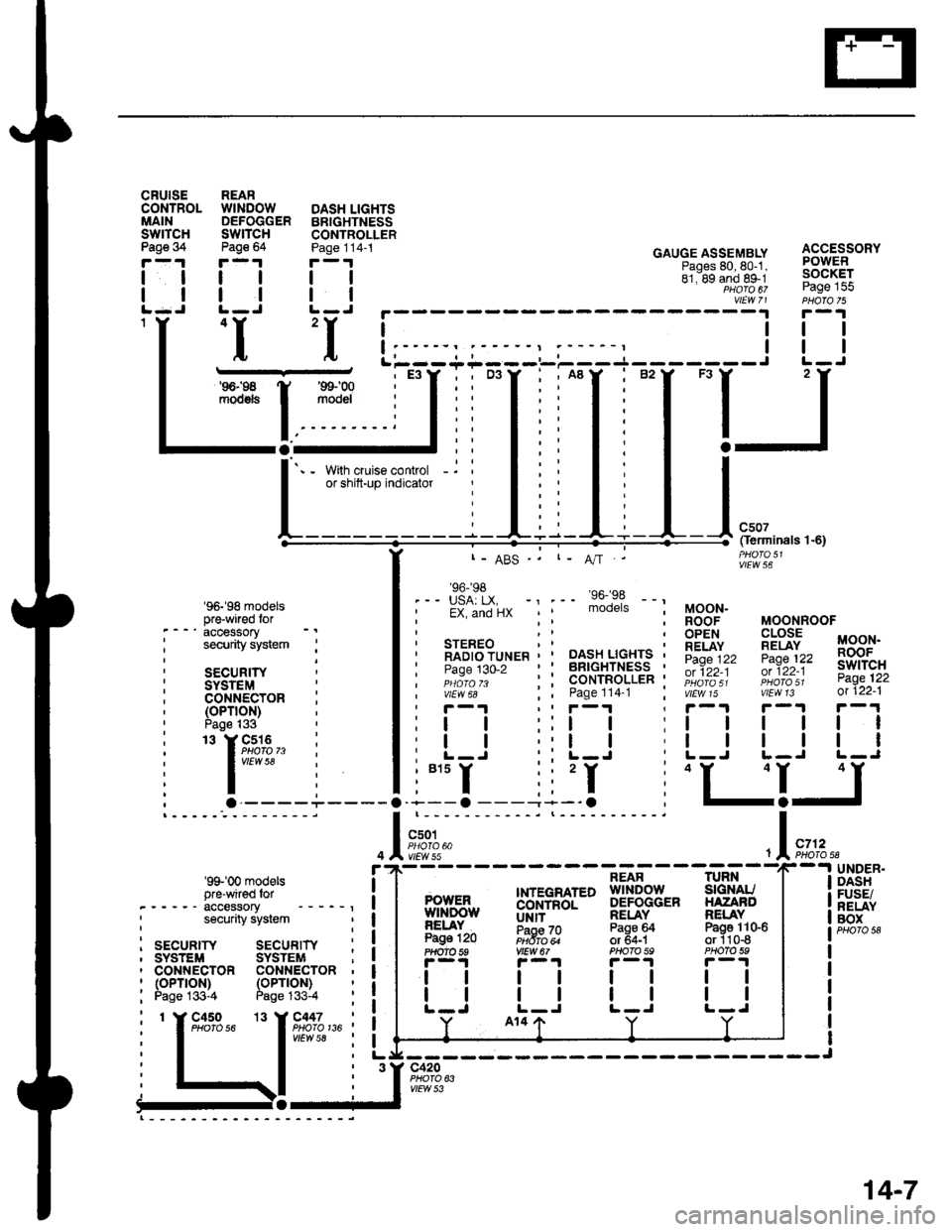
cRutsECONTROLMAINswrTcHPage 34
tl
ll
1Y
. - -' accessory
: security system :
i secun,rY ;
: SYSTEMi coNNEcroR :' (oPTroN)' Page |33
: '. rg;'3,, :, I vrfl,v 58
ili; . ----+
REARWINDOW DASH LIGHTSDEFOGGER BBIGHTNESSSWITCH CONTROLLER
:93' :gl"' Goug:*:FTi\" f3$??'o"'
llll bi:8d;fttie-i:9-9{EJ
aaal ,"|;fl9,,ff%;"
:f :1'L;,:;;-;__:_:::J
i:ir .:,;,-rr-E:
f
,-T,-"T-'-.
[_j,I=
,
lii
f ::'* ,I., l, I -l*,.Oerminals l '6)
'96-'98 modelspr+wi.ed tor
'99'00 modelspre-wired lor-_----accessory, security system
I srcunrw sEcunrrY :, SYSTEM SYSTEM ;i CONNECTOR CONi{ECTOR '' (oPTroN)
: Page 133-4
PHO|O136'
I- ABS -.
.-- USA: LX. -' .-' vo-Jl --', EX, and ilx mooers
vtEw 56
MOONROOF
!!P:',t MooN.
i*:r?, 33,o+"
'iii?,;) i??3;?'
' STEREO' RADTO TUNER ' ' DASH LIGHTS ,' P.da11o-, ' ' BRIGHTNESS '', ,;;;;- - : : coNTRoLLER '', v,iw;;" i i eage tte.t :, r-1 ,r r-1
: | | ::l I I
: | | ':l I. L-J . L-J
i"'r ii'I i
MOON-ROOFOPENRELAYPage 122ot 122-1
vtEw 15
ll
ll
'+--a ---'-*-'O
c50tPHOIO 60vtEw 55
r-1 r-1
tttl
lttlL-J L-J
,l
POWENwrNDowNELAYPage 120?HOm 59
ll
tl
.LIJ
14-7
Page 1871 of 2189
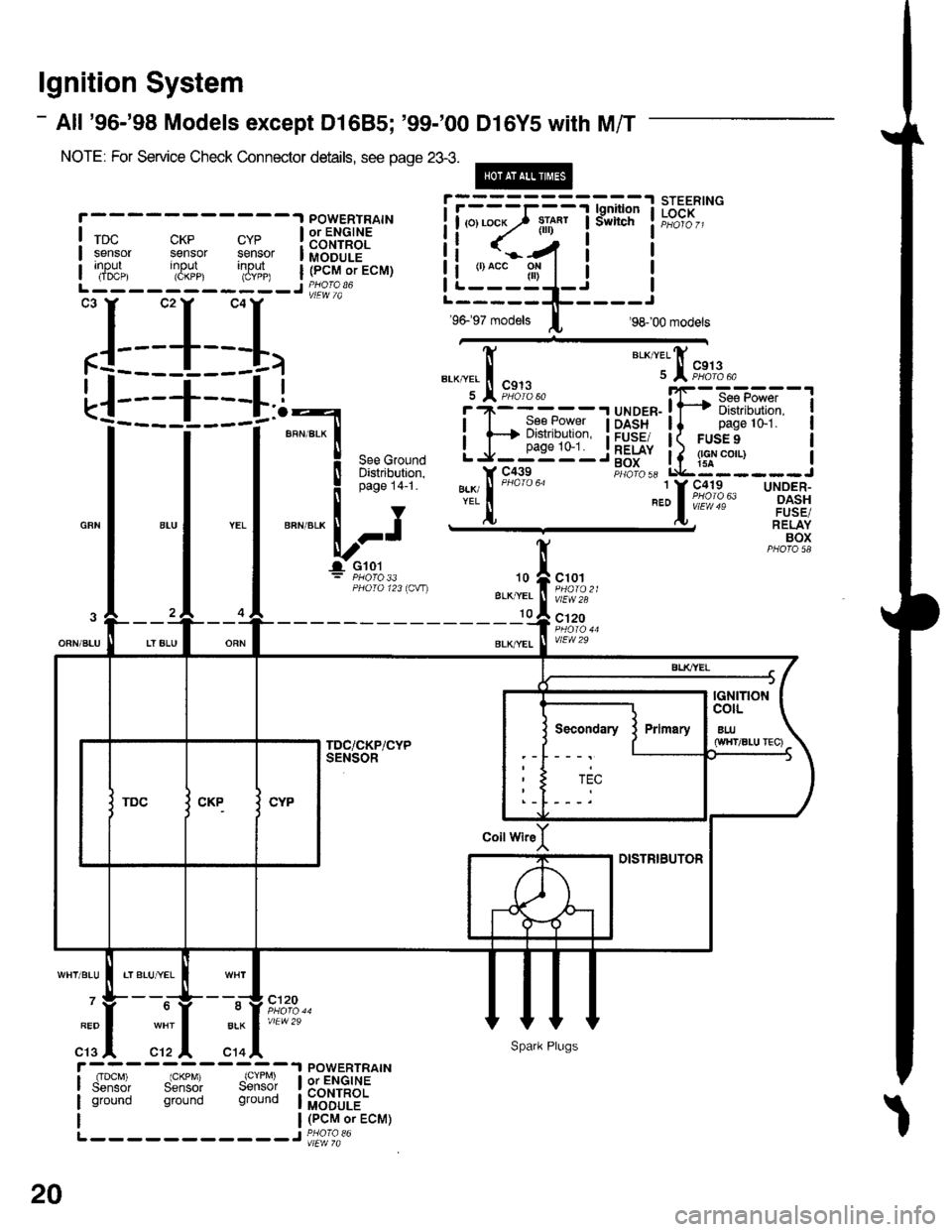
lgnition System
- All '96-'98 Models except Dl685; '99-'00 Dl6Y5 with M/T
NOTE: For Service Check Connector details, see page 23-3.
@
CKP CYPsensor sensorinput input(CKPP) (CYPP)
X,*.,
rDcsensorInpur(IDCP)
POWERTRAINor ENGINECONTROLMODULE(PCM or ECM)
POWERTRAINor ENGINECONTROLMODULE(PCM or ECM)
xr*"
BLKI/EL
I
I
BLK/YEL
I See Power
H Distribution,
J__99'�"'_
I
I
I
I
I
I
UNOER-OASHFUSE/RELAYBOX
"a*,telfi
u I """%t'3.
,rrrr.iFiFx".-,''ril'fi :T-DASH ll pagelo-1.FUSE/ I( FUSE 9
F.itl, Lq::---
".:lo63
10
BLK,YEL
10
c101
vlEW28
c'120
vlEW29
BLK
c14
c120
vlEW29
rIDcM) IGKPM) (CYPM)Sensor Sensor Sensolground ground ground
L-- - - -- -----J PHora 36
L-----------J
:L_1__I,
! iii:?ifq"l
I
**:'
*-"*,t";'
= PHO|O 33PHOTO 123ICW)
Secondary
ti <..-/4 i t
iLi:"_gl_i iL-----1!-----r
96- 97 models I 98- 00 modets
20
Spark Plugs