Page 2134 of 2189
\
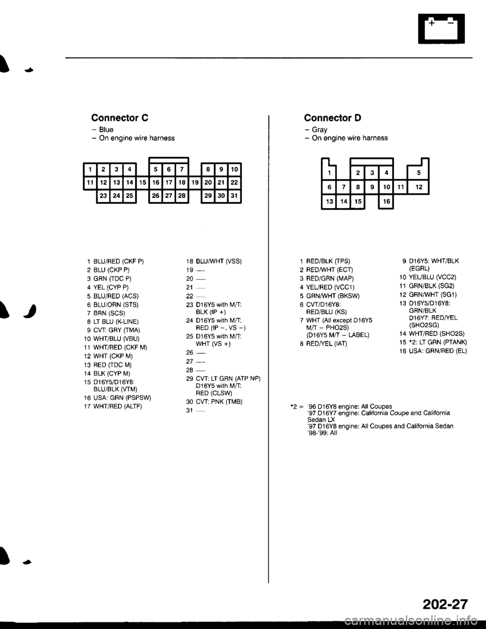
Connector C
- Blue- On engine wire harness
\
1 BLU/RED (CKF P)
2 BLU (CKP P)
3 GRN [rDC P)
4 YEL (CYP P)
5 BLU/REO (ACS)
6 BLU/ORN (STS)
7 BRN (SCS)
8 LT BLU (K.LINE)
I CVT: GRY [rMA)10 WHT/BLU (VBU)
11 WHT/RED (CKF M)
12 WHT (CKP M)
13 RED [rDC M)
14 BLK (CYP M)
1s Dl6Ys/D16Y8iBLU/BLK (VTM)
16 USA: GRN (PSPSW)
17 WHT/RED {ALTF)
18 BLUA/VHT (VSS)
19 -,.
20
21
22
23 016Y5 with l\.4/T:BLK (lP +)
24 D 16Y5 with M/T:RED (rP -, VS -)
25 D16Y5 with M/T:wHT (VS +)
26_
27_
28
29 CW: LT GRN (ATP NP)D16Y5 with l\4/T:RED (CLSW
30 CW: PNK OMB)
t
'I48910
11121314't5't6171819202122
23242526272a293031
L
124
789101112
13141516
Connector D
- Gray- On engine wire harness
1 RED/BLK [TPS)2 REDMHT (ECI)
3 RED/GRN (MAP)
4 YEURED (vCC1)
5 GRN,A/VHT (BKSW)
6 CWD16Y8:RED/BLU (KS)
7 WHT (All except D16Y5M/'T - PHO2S)(D16Y5 M/T - LABEL)
8 RED/YEL (IAT)
I D16Y5i WHT/BLK(EGRr)
10 YEUBLU (VCC2)
11 GRN/BLK (SG2)
12 GRN,ryVHT (SG1)
13 016Y5/D16Y8:GRN/BLKD16Y7: RED//EL(sHo2sG)
14 WHT/REO (SHO2S)
15 '2: LT GRN (PTANI9
16 USA: GRN/RED (EL)
*2 = '96 D16Y8 enoine: All Coupes97 D16Y7 enoine. Calitornia Couoe and CaliforniaSedan LX'97 D16Yg engine: All Coupes and California Sedan'98-�99:All
202-27
Page 2135 of 2189
Connector Views (conrd)
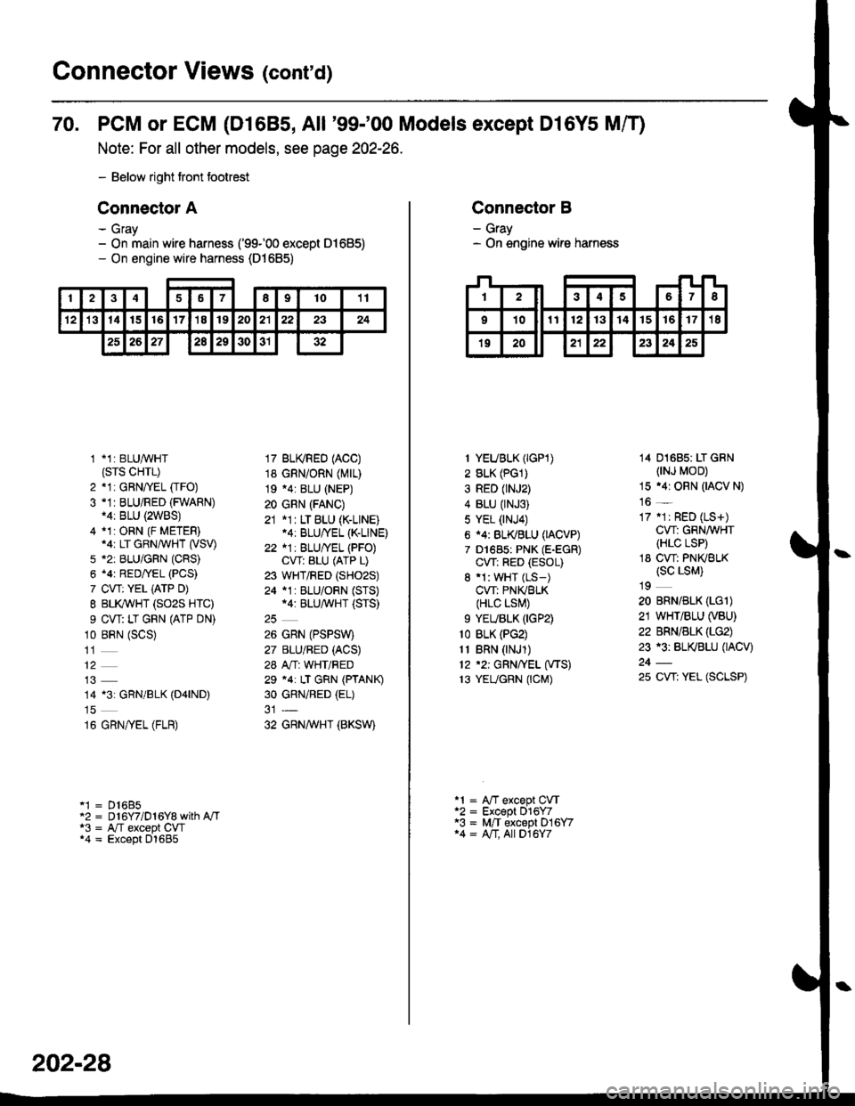
70. PCM or ECM (D1685, All '99-'00 Models except Dl6Y5 Mff)
Note: For all other models, see page 202-26.
- Below right tront footrest
Connector A
- Gray- On main wire harness ('99100 except 01685)- On engine wire harness (D1685)
246789t011
't21314t516'17'18192021222324
2526272a29303132
1 *1: BLUAVHT(srs cHrL)
2 *1: GRNffEL [rFO)3 -1I BLU/RED (FWARN)14: BLU {2WBS)4 *1:ORN (F METER).ar LT GRN/WHT (VSV)
5 *2: BLU/GFN (CRS)
6 .4r RED/YEL (PCS)
7 CVT: YEL iATP D)
I BLI(WHT (SO2S HTC)
9 CW: LT GRN (ATP DN)
10 BRN (SCS)
14 13: GRN/BLK (D4|ND)
16 GRN/yEL (FLR)
'1 = D16B5"2 = D 16Y7/D 1 6Y8 with A"/Ta3 = A,/T except CW*4 = Except D1685
17 BU(RED (ACC)
18 GRN/ORN (Mrr)
19 .4: BLU (NEP)
20 GRN (FANC)
21 *1: LT BLU (K-LINE).4: BLU/YEL (K-LINE)
22 *1: BLU/YEL (PFO)CVT: ALU (ATP L)
23 WHT/RED (SHO2S)
24 *1 : BLU/ORN (STS)*4: BLU/^,iVHT (STS)
26 GRN (PSPSW)
27 BLU/BED (ACS)
28 A"/T: WHT/RED
29 *4: LT GRN (PTANK)
30 GRNiRED (EL)
32 GRNAVHT (BKSW)
202-28
Connector B
- Gray- On engine wire harness
I YEUBLK (IGP1)
2 BLK (PG1)
3 RED (rNJ2)
4 BLU (rNJ3)
5 YEL (NJ4)
6 i4: BL(BLU (IACVP)
7 D1685: PNK (E-EGR)
CW: RED (ESOL)
8 'l: WHT (LS-)
CVT: PNIVBLK(HLC LSI\,!)
9 YEUBLK (IGP2)
1o BLK (PG2)
11 BRN (NJ1)
12 '2: GRN/YEL (VTS)
13 YEUGRN (CM)
14 01685: LT GRN(NJ MOD)
15 .4r ORN (IACV N)
16 _
17 .1r RED (LS+)
CW: GRN/WHT(HLC LSP)
18 CW: PNKBLK(sc LsM)
19
20 BRN/BLK (LGl)
21 WHT/BLU (VBU)
22 BRN/BLK (LG2)
23 r3: BL(BLU (IACV)
25 CW: YEL (SCLSP)
a1 = A"fT except CVTa2 = Except 016Y7'3 = M,/T except D16Y714 = A/T, All D16Y7
Page 2136 of 2189
\I
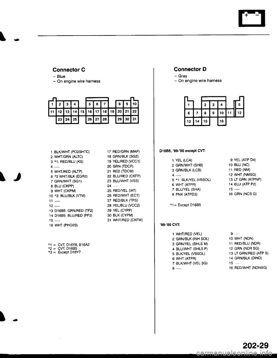
Connector C
- Blue- On engine wire harness
1 BLK/WHT (PO2SHTC)
2 WHT/GRN (ALTC)
3 al: RED/BLU (KS)
5 WHT/RED (ALTP)
6 12 WHT/BLK (EGR2)
7 GRNAVHT (SGl)
8 BLU (CKPP)
9 WHT (CKPM)
10 *3: BLU/BLK (VTM)
13 D1685: GRN/RED OF2)14 01685: BLU/RED (PF2)
16 WHT (PHO2S)
17 RED/GRN (MAP)
18 GRN/BLK (SG2)
1s YEURED (VCC1)
20 GRN (TDCP)
21 RED fiDcl\4)22 BLU/RED (CKFP)
23 BLU,ryVHT (VSS)
24
25 RED/yEL (lAT)
26 REDAVHT (ECT)
27 RED/BLK (TPS)
28 YEUBLU (VCC2)
29 YEL (CYPP)
30 BLK (CYPr,,t)
31 WHTiRED (CKFrVr)
cw D16Y8,816A2cw D1685Except D l6Y7
t
1sl't0234678
111213141516171819202122
23242526272A293031
Connector D
- Gray- On engine wire harness
D1685, '99100 except CW:
1 YEL (LCA)
2 GRN,ryVHT (SHB)
3 GRN/BLK (LCB)
5 .1 : BLIVYEL (VBSOL)
6 WHT (ATPR)
7 BLU/YEL {SHA)8 PNK (ATPD3)
*1= Except D1685
'99100 cw:
1 WHT/RED (VEL)
2 GRN/BLK (rNH SOL)
3 GRN/vEL (SHLS l\4)
4 BLUAVHT (SHLS P)
5 BLK^fEL (VBSOL)
6 WHT (ATPR)
7 BLKWHT (VEL SG)
8
9 YEL (ATP D4)
10 BLU (NC)
11 RED (Ntvl)
12 WHT (NMSG)
13 LT GRN (ATPNP)
14 8LU {ATP P2)
16 GRN (NCS G)
I
1O WHT (NDN)
11 RED/BLU (NDR)
12 GRN (NDR SG)
13 LT GRN/RED (ATP S)
14 GRN/BLK (DIND)
16 REDMHT (NDNSG)
IJ
14
6o10rr ll rz
13141516
202-29
Page 2137 of 2189
Connector Views (conrd)
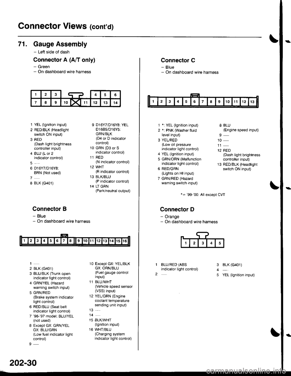
71. Gauge Assembly
- Left side of dash
Connector A (A/T only)
- Green- On dashboard wire harness
1 YEL (lgnition input)
2 RED/BLK (Headlight
switch ON input)
3 RED(Dash light brightnesscontroller input)
4 BLU (L or 2indicator control)
6 D16Y7/D16Y8:BRN (Not used)
8 BLK (G401)
Connector B
- Blue- On dashboard wire harness
2 BLK (G401)
3 BLU/BLK (Trunk openindicator light control)
4 GRN/YEL (Hazard
warning switch input)
5 GRN/RED(Brake system indicatorlight control)
6 RED/BLU (Seat beltindicator light control)
7 '96-'97 model: BLU,ryEL(not used)
8 Except GX: GRN/YELGX: 8LU/GRN(Low fuel indicator lightcontrol)
9 D16Y7/D16Y8: YEL01685/016Y5:GRN/BLK(D4 or D indicatorcontrol)
10 GRN (03 or Sindicator control)
11 RED(N indicator control)
12 WHT(F indicator control)
13 BLI(BLU(P indicator control)
14 LT GBN(Park/neutral output)
10 Except GX: YEUBLKcX: ORN/BLU(Fuel gauge controlinput)
11 BLUAVHT(Vehicle speed sensor(VSS) input)
12 YEUGRN (Engine
coolant temperaturesending unit input)
14
15 BLI(IVHT(lgnition input)
16 WHT/BLU(Charging systemindicator light control)
202-30
Connector C
- Blue- On dashboard wire harness
1 *: YEL (lgnition input)
2 *: PNK (Washer lluidlevel input)
3 YEUBED(Low oil pressureindicator light control)
4 YEL (lgnition input)
5 GRN/ORN (Malfunctionindicator light control)
6 RED/GRN
{Lights on Hl input)
7 GBN/RED (Hazardwarning switch input)
*= '99-'00: All except CVT
Connector D
- Orange- On dashboard wire harness
BLU/RED (ABS
indicator light control)
8 BLU(Engine speed input)
10
12 FED(Dash light brightnesscontroller input)
13 RED/BLK (Headlightswitch ON input)
I
2
3
4
5
BLK (G401)
YEL (lgnition input)
Page 2138 of 2189
\
Connector E
- Groen- On dashboard wire harness
T
Wllh Crulss:
1-
2 RED/BLU (Cruise conkolindicator control)
3 BLK (G401)
Wlth Shtft-up Indlcator:
1 RED(Dash lights brightn€ss
controller inPut)
2 RED/BLU (Shift-up
indicator control)
4 RED/BLK (Headlight
switch ON input)
5 YEL (lgnition input)
BLK (G401)
RED/BLK (Headlight
switch ON input)
YEL (lgnition input)
BLK (G401)
YEL (lgnition input)
3
5
1
2
Connector F
- Yellow- On dashboard wir€ harness
BLU (SRS indicatorlight control)
)-
202-31
Page 2139 of 2189
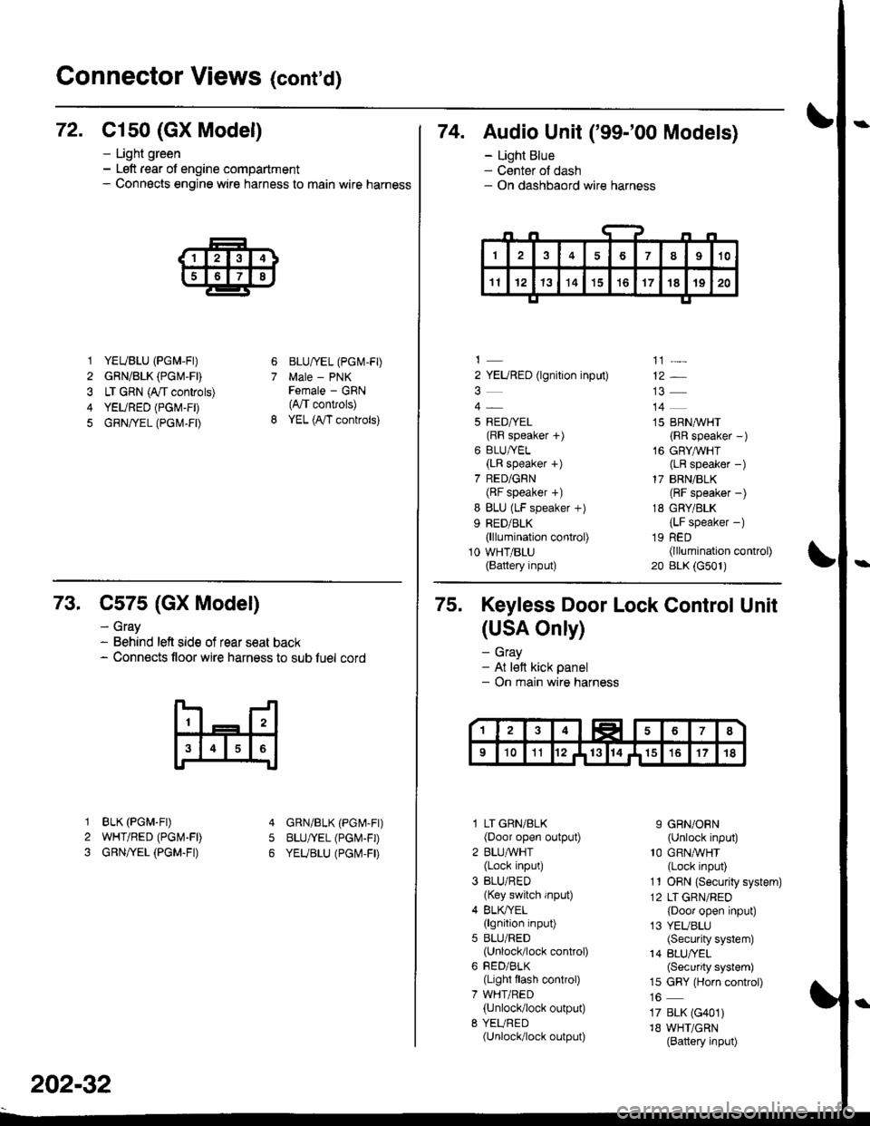
Connector Views (cont'd)
72. C1s0 (GX Model)
1 YEUBLU (PGM-FI)
2 GRN/BLK (PGM.FD
3 LT GRN (A/t controls)
4 YEURED (PGM-FD
5 GRN/rEL (PG|\,1-FD
- Light green- Left rear of engine compartment- Connects engine wire harness to main wire harness
6
7
BLU/IEL (PGM-FD
Male - PNKFemale - GRN(4,/T convols)
YEL (A,/T controls)
74. Audio Unit ('99-'00 Models)
- Light Blue- Center ol dash- On dashbaord wire harness
2 YEURED (lgnition input)
5 RED/YEL(RF speaker f)
6 BLU/YEL(LR speaker +)
7 RED/GRN(BF speaker +)
I BLU (LF speaker +)
9 RED/BLK(lllumination control)
10 WHT/BLU(Battery input)
']]]-
12*
14
15 BRN,^/VHT
{RR speaker -)
16 GRYAVHT(LR speaker -)
17 BRN/BLK(RF speaker -)
18 GRY/BLK
{LF speaker -)
19 RED(lllumination control)
20 BLK (G501)
73. C575 (GX Model)
BLK (PGM.FD
WHT/RED (PGI\4-FD
GRN/YEL (PGM.FI)
- Gray- Behind left side of rear seat back- Connects floor wire harness to sub luel cord
5
1
2
3
GRN/BLK (PGr\4-Fr)
BLU/YEL (PGI\'-FD
YEUBLU (PGI\,4,FD
202-32
75. Keyless Door Lock Control Unit
(USA Only)
- Gray- At lett kick panel- On main wire harness
l LT GRN/BLK(Door open output)
2 BLU,ryVHT(Lock input)
3 BLU/RED(Key switch input)
4 BLK/YEL(lgnition input)
5 BLU/RED(Unlock/lock control)
6 FED/BLK(Light flash control)
7 WHT/RED(Unlock/lock output)
8 YEURED(Unlock/lock output)
9 GRN/ORN(Unlock input)'10 GRNA/VHT(Lock input)
11 ORN {Securiiy system)
12 LT GRN/RED
{Door open input)
13 YEUBLU(Security system)
14 BLU/YEL(Security system)
15 GRY (Horn control)
17 BLK (G401)
18 WHT/GRN(Battery input)
Page 2140 of 2189
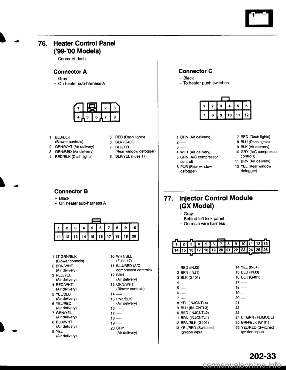
76. Heater Control Panel
('99100 Models)
- Center of dash
Conneclor A
- Gray- On heater sub-harness A
BLUi BLK(Blower controls)
GRNAVHT (Air delivery)
GRN/RED (Air delivery)
RED/BLK (Dash lights)
Connector B
- Black- On heater sub-harness A
7
8
1
4
RED (Dash lights)
BLK (G402)
BLUfYEL(Rear window defogg€0
BLK,TYEL (Fuse 17)
\
)
1 LT GRN/BLK(Blower controls)
2 BRN,A/VHT(Air delivery)
(Air delivery)
4 REDA/VHT(Air delivery)
5 YEUBLU(Air delivery)
6 YEURED(Air delivery)
7 GRN/YEL(Air delivery)
8 BLU,ryVHT(Air delivery)
9 YEL
{Air delivery)
1O WHT/BLU(Fuse 47)
11 BLU/RED WCcompressor controls)
12 BRN(Air delivery)
13 ORNAVHT(Blower controls)
14 -
15 PN(BLK(Air delivery)
16 _
19 _
20 GRY(Air delivery)
Connector C
- Black- To heater push switches
1 ORN (Air delivery)
2
4 WHT (Air delivery)
5 GRN (ry'C compressorcontrol)
6 PUR (Roar windowdelogge4
7 RED (Dash lights)
8 BLU (Dash lights)
I BLK (Air delivery)
10 GRY (Ay'C compressorcontrols)
1'1 BRN (Air delivery)
12 YEL (Rear window
defogge0
77. Injector control Module
(GX Model)
- Gray- Behind left kick panel- On main wire harness
1 RED (rNJ2)
2 BRN (rNJl )3 BLK (G401)
4_
8 YEL (TNJCNTL4)
9 BLU (TNJCNTL3)
1o RED (tNJCNTL2)
11 BRN 0NJCNTL1)12 BRN/BLK (G101)
13 YEURED (Switched
ignition input)
14 YEL (tNJ4)
15 BLU (rNJ3)
16 BLK (G401)
19 -
20-
21
24 LI GRN (INJMODE)
25 BRN/BLK (Gr 01)
26 YEURED (Switched
ignition input)
202-33
Page 2141 of 2189
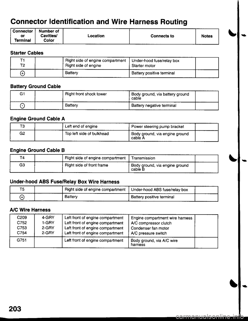
Connector ldentification and Wire Harness Routing
Connector
or
Terminal
Number of
Cavities/
Color
LocationConnects toNotes
Starter Cables
T1
r2
Right side of engine compartment
Right side of engine
Under-hood luse/relay box
Staner motor
t+lBatteryBattery positive terminal
Battery Ground Cable
Right front shock towerBody ground, via battery ground
cable
oBatteryBattery negative terminal
Engine Ground Cable A
t!tLeft end of enginePower steering pump bracket
Too left side ot bulkheadBody ground, via engine ground
cable A
Engine Ground Cable B
T4Bight side of engine compartmentTransmission
(ritRight side of front frameBody ground, via engine ground
Under-hood ABS Fuse/Relay Box Wire Harness
tcRight side of engine compartmentUnder-hood ABS fuse/relay box
oBatteryBattery positive terminal
A,/C Wire Harness
c209
wtJl/,\-7Ee
c754
4-GRY
1.GRY
2-GRY
2-GRY
Lefl front of engine compartment
Left front of engine compartment
Lefl front of engine compartment
Left tront of engine compartment
Engine compartment wire harness
A,/C compressor clutch
Condenser fan motor
A,/C pressure switch
G751Left front of engine compartmentBody ground, via A,/C wireharness