2000 HONDA CIVIC clutch
[x] Cancel search: clutchPage 840 of 2189

Clutch
Reassembly
NOTE:
. Clean all parts thoroughly in solvent or carburetor
a
cleaner, and dry them with compressed air.
Blow out all passages.
Lubricate all parts with ATF before reassembly.
Inspect the check valve; if it's loose, replace the pis-
to n.
1.
CHECK VALVE
2. Install new O-rings on the clutch piston.
O RINGS
PISTON
-
14-162
3. Install the piston in the clutch drum, Apply pressure
and rotate to ensure proper seating,
NOTE: Lubricate the piston O-ring with ATF beforeinstalling.
CAUTION: Do not pinch the O-ring by insta ing thepiston with too much force.
CLUTCII DRUM
Install the return spring and spring retainer, andposition the snap ring on the retainer.
CLUTCI{ DRUM
Page 841 of 2189

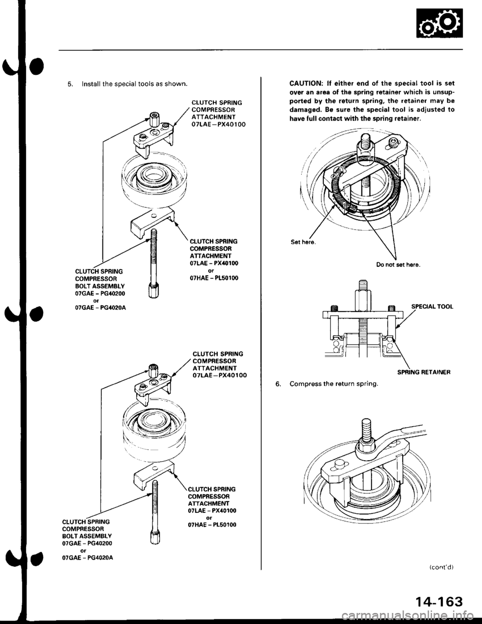
5. Install the special tools as shown.
CLUTCH SPRINGCOMPRESSORATTACHMENT07LAE - PX40100
CLUTCH SPRINGCOMPRESSORATTACHMENT07LAE - PX40100or07HAE - P150100
CLUTCH SPRINGCOMPRESSORATTACHMENT07LAE -PX40100
CLUTCH SPRINGCOMPRESSORATTACHMENT07LAE - PX4010o
07HAE - PL50100CLUTCH SPRINGCOMPRESSORBOLT ASSEMBLY07GAE - PG40200
O7GAE. PG4O2OA
SPRING
CAUTION: lf eithe. end of the sDecial tool is set
over an area of the spring retainer which is unsup-
ported by the rsturn spring, the ietainer may be
damaged. Bs sure the special tool is adjusted to
have full contact with the spring retainer.
Sot hsro.
SPECIAL TOOL
RETAINER
6. Compress the return spring.
(cont'd )
Do not sot hore.
14-163
Page 842 of 2189

Glutch
Reassembly (cont'd)
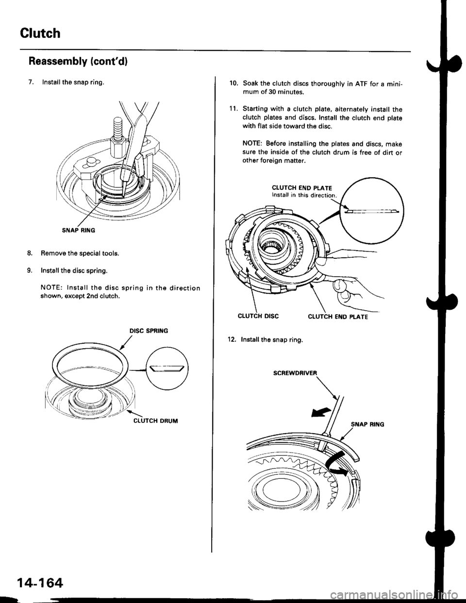
7. Installthe snap ring.
Removs the special tools.
Install the disc spring.
NOTE: Install the disc spring in the direction
shown, except 2nd clutch.
SNAP RING
8.
o
14-164
h
10.
ll.
Soak the clutch discs thoroughly in ATF for a mini-
mum of 30 minutes.
Starting with a clutch plate, alternately install the
clutch plates and discs. Install the clutch end plate
with flat side toward the disc.
NOTE: Before installing the plates and discs, make
sure the inside of the clutch drum is free of din orother foreign mafter.
CLUTCH END PLATEInstall in this direcrion.
12. Installthe snap ring.
SCREWDRIVER
SNAP RING
Page 843 of 2189

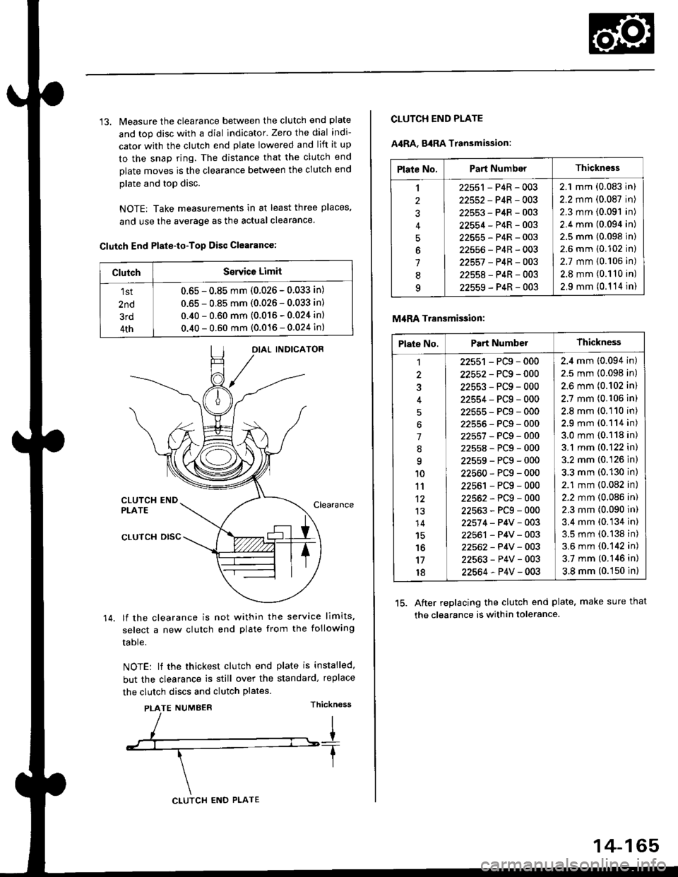
13. Measure the clearance between the clutch end plate
and top disc with a dial indicator' Zero the dial indi-
cator with the clutch end plate lowered and lift it up
to the snap ring. The distance that the clutch end
plate moves is the clearance between the clutch end
plate and top disc.
NOTE| Take measurements in at least three places,
and use the average as the actual clearance.
Clutch End Plste-to-Top Disc Clearance:
OIAL INDICATOR
CLUTCH ENDPLATEClearance
14.
CLUTCH DISC
lf the clearance is not within the service limits,
select a new clutch end plate from the following
table.
NOTE: lf the thickest clutch end plate is installed,
but the clearance is still over the standard, replace
the clutch discs and clutch plates.
PLATE NUMBERThickn6ss
ClutchSerYice Limit
1st
2nd
3rd
4th
0.65 - 0.85 mm (0.026 - 0.033 in)
0.65 - 0.85 mm (0.026 - 0.033 in)
0.40 - 0.60 mm (0.016 - 0.024 in)
0.40 - 0.60 mm (0.016 - 0.024 in)
CLUTCH ENO PLATE
14-165
Plate No.Part NumberThickness
,l
2
J
4
5
6
1
8q
22551 - P4R - 003
22552-P4R-003
22553-P4R-003
22554-P4R-003
22555-P4R-003
22556-P4R-003
22557 -P4B-OO3
22558-P4R-003
22559-P4R-003
2.1 mm (0.083 in)
2.2 mm (0.087 in)
2.3 mm (0.091 in)
2.4 mm (0.094 in)
2.5 mm (0.098 in)
2.6 mm (0.102 in)
2.7 mm {0.106 in)
2.8 mm {0.110 in)
2,9 mm (0.1 '14 in)
CLUTCH END PLATE
A4RA, g4RA Transmission:
M,IRA Transmi$ion:
15. After replacing the clutch end plate. make sure that
the clearance is within tolerance.
Plate No.Part NumberThickness
1
3
'l
.'q
10
11't2
13
14
15'16
17
18
22551 - PCg - 000
22552-PCg-000
22553-PCg-000
22554-PCg-000
22555-PCg-000
22555-PCg-000
22557-PCg-000
22558-PCg-000
22559-PCg-000
22560-PCg-000
22561 - PCg - 000
22562-PCg-000
22563-PCg-000
22574 - P4V - 003
22561 - P4V - 003
22562- P4V - 003
22563-P4V-003
22564-P4V-003
2.4 mm (0.094 in)
2.5 mm (0.098 in)
2.6 mm {0.102 in)
2.7 mm (0.106 in)
2.8 mm (0.110 in)
2.9 mm (0.114 in)
3.0 mm {0.118 in)
3.1 mm (0.122 in)
3.2 mm (0.126 in)
3.3 mm (0.130 in)
2.1 mm (0.082 in)
2.2 mm {0.086 in)
2.3 mm (0.090 in)
3.4 mm (0.134 in)
3.5 mm (0.138 in)
3.6 mm (0.142 in)
3.7 mm (0.146 in)
3.8 mm (0.150 in)
Page 858 of 2189

Transmission
26. Slip the special tool onto the mainshaft as shown,
MAINSHAFT HOLDER07GAB - PF50101
Installthe park lever on the control shaft.
Assemble the one-way clutch and the park gearwith the countershaft lst gear (see page l4-1S5).
Install the countershaft lst gear collar. needle bear_ing, and the countershaft 1st gearlpark gear assembly
Reassembly (cont'dl
on the countershaft.
lSTCLUTCH PARKASSEMBLY GEAR
27.
28.
29.
30.Install the park pawl shaft, spring, pawl, and pawlstop on the transmission housing, then engage thepark pawlwith the park gear.
14-180
31. Install the mainshaft 1st gear collar on the main_shaft.
32. Wrap the shaft splines with tape to prevent the O-rings, then install new O-rings on the mainshaft,
33. Assemble the thrust washer, thrust needle bearing,needle bearing, and mainshaft ?st gear in the lstclutch assembly, then install them on the mainshaft.
34. Install new conical spring washers and locknuts oneach shaft.
CAUTION: Install the conical spring washers in thedirection shown.
MAINSHAFTLOCKNUTLeft hand threads
CONICAL SPRING WASHERSinstall in this direction.
35. Tighten the locknuts to the specified torque.
NOTE:
. Do not use an impact wrench. Alwavs use atorque w.ench to tighten the locknut.. Mainshaft and countershaft locknuts have left_hand threads.
TOROUE:
MAINSHAFT 78 N.m (8.0 kgf.m, 58 tbf.ft)COUNTERSHAFT t03 N.m 1r0.5 kgf.m, 75.9 tbt.ftl
Page 871 of 2189

Continuously Variable Transmission (CVTI
Special Tools ................ 14-194
Description .................... 14-195
Clutches/Reverse Brake/Planetary
Gear/Pulleys .......... 14-198
power Flow ..............,..... 14-200
Electronic Control SYstem(,96 - 98 Modets) ......14-203
Electronic Control System
('99 - oo Models) " 14-205
Hydraulic Control '....... 14-208
Hydraulic Flow .'..-.....'... '14-212
Park Mechanism .....-...'.' 14-222
Eleqtrical Systom
Component Locations'96 - 98 Models """"""' 14-224,99 - 00 Modets ............. 14-225
TCM Circuit Diagram ('96 - 98 Models) ............. 14-226
TCM Terminal Voltage/Measuring Condiiions ('96 - 98 Models) '.... 14-228
PcM Circuit Oiaqram{A/T Control System: '99 - 00 Models} ...--.... 14-230
PCM Terminal Voltage/Measuring Conditions('99 - 00 Models)
A/4 Control System .'.'...14-232
Troubleshooting Procedures ... . .... .....',........."' '14-234
Symptom-to-ComPonent Chart
Electrical System - '96 - 98 Models ......'..... '14-234
Electrical System -'99 - 00 Models ..'....-..-. '11-210
Electrical Troubleshooting
Troubleshooting Flowcharts('96 - 98 Models) """'11-242
Troubleshooting Flowchart
('99 - 0O Modets) ...... 14-265
Linear Solenoids/lnhibitor Solenoid
Test ......................... . ...... 14-29f
Drive Pulley/Driven Pulley/Secondary Gear
Shaft Speed Sensors
Replacement .........'...... .14-292
Start Clutch Control
Start Clutch Calibration Procedure ....... ....,. 14-293
Hydraulic SYstem
Symptom-to-ComPonent Chart
Hydraulic System '.'.......14-294
Road Test ............................ 14-296
Stall Speed
Test......................... ...... 14-294
Fluid Level
Checking/Changing ....... 14-299
Pressure Testing ................. 14-300
Lower Valve BodY AssemblY
Replacement ..........,... 14-302
ATF Filter
Removal/lnstallation ..... 14-303
Transmission
Transmission
Removal ........... . 14-304
lllustrated Index
Transmission/Lower Valve BodY
Assembly ................. 14-308
Transmission Housing/Flywheel Housing ... 14-310
End Cover/f ntermediate Housing ..........'.'.... 14-312
Transmission Housing/Lower Valve Body Assembly
Removal ..........'.... .. " 14-314
Transmission Housing/Flywhesl Housing
Removal ................. ........ 1+316
End Cover/lntermediate Housing
14-318Removal .........,...............
Manual Valve Body
Disassembly/lnspection/Reassemblv .'.'.'..... 1 4-320
Forward Clutch
lltustrated Index ........................................ 14-321
Disassemblv .................. 14-322
Reassemblv , ,, . ',','......14-324
Secondary Gear Shaft
25 x 35 mm Thrust Shim Selection ..'.'....-... 14-324
Differential
lllustrated lndex ...,.....................,.,...-.-.-...'... 14-329
Backlash Inspection .-....14-329
Bearing Replacement ......'........'....'... ....'... 14-330
Differential Carrier Replacement ........'........ 14-330
Oil Seal Removal ........... 14-331
Oil Seal Installation/Side Clearance ....... . . 14-331
Flywheel Housing Input Shaft Oil Seal
Replacement .....,.... ...'.'.. 14-333
Transmission Housing Bearings
Driven Pulley Shaft Bearing
Replacenient ...................'. . ...................'.. 14-334
Secondary Gear Shaft Bearing
Reolacbment ...................... . .......... . ........ 14-335
Flywheel Housing Beating
Secondary Gear Shaft BearingReo1acement..................,........................... 14-335
Ring Gear Bearing
Replacement......... ........ 14-336
Control Shaft Assembly
Removal/lnstallation ....................'........... 14-336
Transmission
Reassembly .................. 14-338
Flywheel/Drive Plate .. . ...... . ...... ... . ....-.....'.'...14-341
Transmission
lnstalation ..................... 14-348
Cooler Flushing .'......... 14-352
shift cable
Removal/lnstallation....'........." """ 14-354
Adjustment .......'........ 14-355
Shift Lever ........................,. 14'356
Shift Indicator Panel
Adjustment ................ 14-357
ATF Cooler/Hoses
lnsta llation ......,,...... .... 14-357
Page 872 of 2189

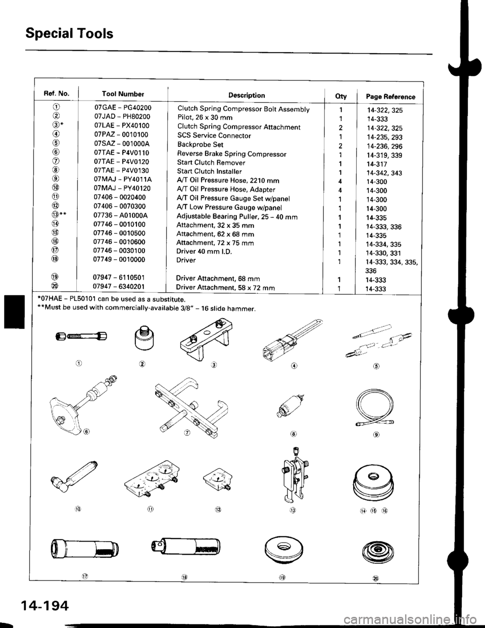
Special Tools
Ref. No. I Tool Number
o
@alr *
@
o
@6l
@
o
@
@-"
@
@
@
o
@
07GAE - PG40200
07JAD - PH80200
07LAE - PX40100
07PM - 0010100
07sM- 0010004
07TAE - P4V01l0
07TAE - P4V0120
07TAE - P4V0130
07 tvlAJ - PY4011A
07MAJ - PY40l20
07406 - 0020400
07406 - 0070300
07736 - A0r 0004
07746 - 0010100
07746 - 0010500
07746 - 0010600
07746 - 0030100
07749 - 0010000
07947 - 6110501
01947 - 6340201
Clutch Spring Compressor Bolt AssemblyPilot. 26 x 30 mm
Clutch Spring Compressor Attachment
SCS Service Connector
Backprobe Set
Reverse Brake Spring Compressor
Stan Clutch Remover
Stan Clutch Installer
A/T Oil Pressure Hose,2210 mmAy'T Oil Pressure Hose, Adapter
Ay'T Oil Pressure cauge Set WpanelAy'T Low Pressure Gauge w/panel
Adjustable Bearing Puller, 25 - 40 mmAttachment, 32 x 35 mm
Attachment, 62 x 68 mm
Attachment, 72 x 75 mm
Driver 40 mm l.D.
Driver
Driver Aftachment, 68 mm
Driver Attachment, 58 x 72 mm
I
1
2
Ia,l
1
1
1,1
1
1'1
I
1
1
't4-322,325
14-333
14-322,325't4-235,293
14-236, 296
r4-319,339't 4-311
14-342,343't4-300
14-300
14-300
14-300
14-335
14-333, 336
14-335
14-334, 335
14-330, 331
14-333, 334, 335,
336
14-333
14-333*07HAE - PL5010l can be used as a substitute.**Must be used with commercially-available 3/8.,- 16 slide hammer.
E*E
o
e
@
>.'.- -t-'- t'\;4
e'o
1:,'Jt*
dAt:-
io(313
@
@
@
@18l
aio
@
IR
L
14-194
Page 873 of 2189

Description
The Continuously Variable Transmission (CVT) is an electronically controlled automatic transmission with drive and driv
en Oullevs, and a steel belt. The CVT provides non stage speeds forward and one reverse. The entire unit is positioned in
line with the engine.
Transmission
Around the outside of the flywheel is a ring gear which meshes with the starter pinion when the engine is being staned.
The transmission has four parallel shafts: the input shaft, the drive pulley shaft. the driven pulley shaft, and the secondary
gear shaft. The input shaft is in line with the engine crankshaft. The drive pulley shaft and the driven pulley shaft consist of
movable and fixed face pulleys. Both pulleys are linked by the steel belt.
The input shaft includes the sun gear. The drive pulley shaft includes the forward clutch which mounts the carrier assem-
bly on the forward clutch drum. The carrier assembly includes the pinion gears which mesh with the sun gear and the ring
gear. The ring gear has a hub-mounted reverse brake disc.
The driven pulley shaft includes the start clutch and the secondary drive gear which is integral with the park gear' The sec-
ondary gear shaft is positioned between the secondary drive gear and the final driven gear. The secondary gear shaft
includes the secondary driven gear which serves to change the rotation direction. because the drive pulley shaft and the
driven oullev shaft rotate the same direction. When certain combinations of planetary gears in the transmission are
engaged by the clutches and the reverse brake, power is transmitted from the drive pulley shaft to the driven pulley shaft
to provide E, E, E, and El.
Electronic Control'96 - 98 Models:
The electronic control system consists of the Transmission Control Module (TCM), sensors, three linear solenoids, and a
inhibitor solenoid. Shifting is electronically controlled under all conditions'
The TCM is located below the dashboard, behind the kick panel on the driver's side.'99 - 00 Models:
The electronic control svstem consists of a Powertrain Control Module (PCM), sensors, three linear solenoids and an
inhibitor solenoid. Shifting is electronically controlled under all conditions. A Grade Logic Control System to control shift-
ing in E position while the vehicle is ascending or descending a slope.
The PCM is located below the dashboard, under the kick panel on the passenger's side.
Hydraulic Control
The lower valve body assembly includes the main valve body, the Pressure Low (PL) reguiator valve body, the shift valve
body, the start clutch control valve body, and the secondary valve body. They are positioned on the lower part of the
transmission housing.
The main valve body contains the Pressure High (PH) control valve, the lubrication valve, and the pitot regulator valve.
The secondary valve body contains the PH regulator valve, the clutch reducing valve, the start clutch valve accumulator,
and the shift inhibitor valve. The PL regulator valve body contains the PL regulator valve and the PH-PL control valve
which is ioined to the PH,PL control linear solenoid. The inhibitor solenoid valve is bolted on the PL regulator valve body.
The shift valve body contains the shift valve and the shift control valve. which is joined to the shift control linear solenoid.
The start clutch control valve body contains the start clutch control valve, which is joined to the start clutch control linear
solenoid. The linear solenoids and the inhibitor solenoid are controlled by the TCM or PCM. The manual valve body which
contains the manual valve and the reverse inhibitor valve, is bolted on the intermediate housing.
The ATF pump assembly is located on the transmission housing, and is linked with the input shaft by the sprockets and
the sprocket chain. The pulleys and the clutch receive fluid from their respective feed pipes, and the reverse brake receives
fluid from internal hydraulic circuit.
Shift Control Mechanism
Input from various sensors located throughout the vehicle determines which linear solenoid the TCM or PCM will activate.
Activating the shift control linear solenoid changes the shift control valve pressure, causing the shift valve to move. This
pressurizes the drive pulley pressure to the drive pulley and the driven pulley pressure to the driven pulley and changes
their effective pulley ratio. Activating the start clutch control linear solenoid moves the start clutch control valve. The start
clutch control valve uncovers the port, providing pressure to the start clutch to engage it(cont'd)
14-195
,!