Page 1827 of 2189
How To Use This Manual
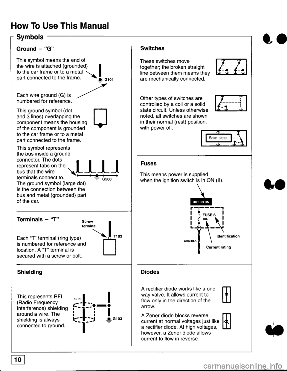
Symbols
Ground - "G"
This symbol means the end ol
the wire is attached (grounded) Ito the car frame or to a metal I
part connected to the frame. \i oro,|
-t'
Each wire ground (G) it --/
numbered for reference.
oo
Switches
These switches move
together; the broken straight
line between them means the,
are mechanically connected.
Other types of switches are
controlled by a coil or a solid
state circuit. Unless otherwise
noted. all switches are shown
in their normal (rest) position,
with power off.
This ground symbol (dot
and 3 lines) overlapping the
component means the housing
of the component is grounded
to the car frame or to a metal
part connected to the frame.
This symbol represents
the bus inside a ground
connector. The dots I
i:l*,':1,'^:*,:"
;"
r"L I I I
terminals connect to.
The ground symbol (large dot)
is the connection between the
bus and metal (grounded) part
of the car.
Terminals - "T"
ffi
ffi
Solid-state
Fuses
This means power is supplied
when the ignition switch is in ON (ll).
Current rating
Diodes
A rectifier diode works like a one
way valve. lt allows current to
llow only in the direction of the
arrow.
A Zener diode blocks reverse
current at normal voltages just like
a rectifier diode. At high voltages.
however, a Zener diode allows
current to f low in reverse
oo
Each "T" lerminal (ring type)
is numbered for reference and
location. A "T" terminal is
secured with a screw or bolt.
Shielding
This represents RFI
(Radio Frequency
Interference) shielding
around a wire. The
shielding is always
connected to ground.
f--l;j-i",..
I
,,,,
T
Page 1828 of 2189
Five-Step Troubleshooting
L Verify The Complaint
Turn on all the components in the problem
circuil lo check the accuracy of the customer
complaint. Note the symptoms. Do not begin
disassembly or testing until you have
narrowed down the problem area.
2. Analyze The Schematic
Look up the schematic for the problem
circuit. Determine how the circuit is
supposed to work by tracing the current
paths lrom the power source through the
circuit components to ground. Also, trace
circuits that share wiring with the problem
circuit. The names of circuits that share the
same fuse, ground, or switch, and so on, are
referred to in each circuit schematic. Try to
operate any shared circuits you didn't check
in step 1 . lt the shared circuits work, the
shared wiring is OK, and the cause must be
in the wiring used only by the problem
circuit. lf several circuits fail at the same
time, the fuse or ground is a likely cause.
Based on the symptoms and your
understanding of the circuit's operation,
identify one or more possible causes.
3. lsolate The Problem By Testing The Circuit
Make circuit tests to check the diagnosis
you made in step 2. Keep in mind that a
logical, simple procedure is the key to
efficient troubleshooting. Test for the most
likely cause of failure first. Try to make tests
at points that are easily accessible.
4. Fix The Problem
Once the specific problem is identified,
make the repair. Be sure to use proper tools
and safe procedures.
5. Make Sure The Circuit Works
Turn on all components in the repaired
circuit in all modes to make sure you've
fixed the entire problem. ll the problem was
a blown fuse, be sure to test all of the
circuits on that fuse. Make sure no new
problems turn up and the original problem
does not recur.
Test Equipment
Most circuits include solid-state devices.
Test the voltages in these circuits only with
a 1o-megaohm or higher impedance digital
mUltimeter. Never use a test light or analog
meter on circuits that contain solid-state
devices. Damage to the devices may result.
Test Light and DVOM
On circuits without solid-state devices, use a
test light to check for voltage. A test light is
made up of a 12 volt bulb with a pair of leads
attached. After grounding one lead, touch the
other lead to various points along the circuit
where voltage should be present. The bulb
will go on if there is voltage at the point being
tested. lf you need to know how much
voltage is present, use a digital
volVohmmeter (DVOM).
Self-Powered Test Light and DVOM
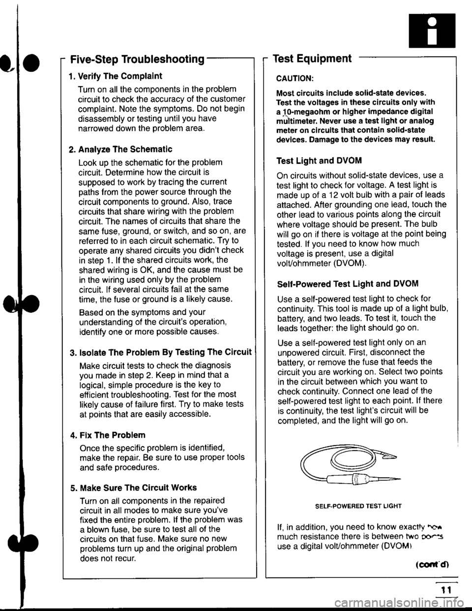
Use a self-powered test light to check for
continuity. This tool is made up of a light bulb,
battery, and tlvo leads. To test it, touch the
leads together: the light should go on.
Use a self-powered test light only on an
unoowered circuit. First, disconnect the
battery, or remove the fuse that feeds the
circuit you are working on. Select two points
in the circuit belween which you want to
check continuity. Connecl one lead of the
self-powered test light to each point. lf there
is continuity, the test light's circuit will be
completed, and the light will go on.
SELF-POWERED TEST LIGHT
lf, in addition, you need lo know exacW hc'.
much resistance there is between two oo'^=
use a digital volUohmmeter (DVOM)
acdrt'Cn
t1
Page 1835 of 2189
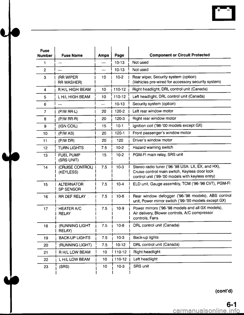
Fuse
NumberAmpsPageFuse Name
(RR WIPER
RR WASHER)
i R HiL HIGH BEAM | 10
L H/L HIGH BEAM
| (PAIV RR-L)
i (P/vv RR-R)
(rGN CO|L)
10I (P,^/V AS)
Component or Circuit Protected
Not used
Not used
Rear wiper, Security system (option)
(Vehicles pre-wired for accessory security system)
'10r 1n-2
I
| 1 10-12i Right headlight, DRL control unit (Canada)
Lett headlight, DRL control unit (Canada)
I ro-rsSecurity system (option)
| 120-2 | Left rear window motor
Right rear window motor
lgnition coil ('98-'00 models except GX)
| 120-1 | Front passenger's window motor
i (PiW DH)| 20 1 12O I Driver's window motor
TURN LIGHTSHazard warning switch
FUEL PUMP
(SRS UNIT)
PGM-FI main relav, SRS unit
(cRUrsE CoNTROL)
/KtrVt trSS\
Stereo radio tuner ('96-'98 USA: LX, EX, and HX),
Cruise control main switch, Keyless door lock
control unit ('99-'00 models with keyless entry)
15ALTERNATOR
SP SENSOR
l-a10-4I ELD unit, Gauge assembly, TCM (96-'98 CW, PGM-FI
16I RR DEF RELAY7.510-8I Rear window defogger ('96-'98 models), ABS control
I unit. Power mirror switch ('99-'00 models except GX)
i-HEATER r/C
I RELAY
Power mirrors ('96-98 models and all GX models),
Air delivery, Blower controls, AilC compressor
controls, Fans
I (RUNNING LIGHT
I RELAY)
1 7.5 1
tl
I DRL control unit (Canada)
i BACK-UP LTGHTSi Back-up lights
(RUNNING LIGHT)DRL control unit (Canada)
I R H/L LOW BEAM'10 l11o-12Right headlight
I L H/L LOW BEAM | 101110-12 | Left headlight
(cont'd)
(SRS)SRS unit
6-1
Page 1836 of 2189
- Under-dash Fuse/Relay Box (cont'd)
Fuse/Relay I nformation
Fuse
NumberFuse NameAmps
(P/W RELAY)
(S/R RELAY)
FR WIPER
FR WASHER
LO
Page
10-7 |
I
Component or Clrcuit Protected
i Power window relay, Moonrool
Front wioer/washer
CIGARETTE
LIGHTER
ACC SOCKET
10-7Accessory power socket
I RAD|O CLOCK
I
110 115)l
tl
1O-7 |
I
Stereo radio tuner ('96198 models), Audio unit ('99100
model)
Not used
i 7.5i 114 iDash & console lights
I srnnrensrorunl | 7.slzl , zt -t , ! eCU-n main retay, PCM/ECM, Integrated controt unit
I ot 21-2 t
I LICENSE LIGHTS I 7.5
I rerr uesls I
Parking lights, License plate lights, Tail lights| 1oo-1 |
tl
| (f NTERLOCK UNIT) | 7.5 | 10-12 I Interlock system
* = '98 models
6-2
Page 1839 of 2189
Fuse
NumberFuse NameAmpsPage
BATTERY
Component or Circult Protected
Power distribution
lgnition switch
INTERIOR LIGHT | 7.5 | 10-10 | DLC, Ceiling light, Trunk light
FI E/M15 i(20 GX) i
i PGM-FI main relay, Fuel injection relay (GX)
Not used
POWER WINDOW| 10-10 | Power window relay
BACK UPStereo radio iuner ('9G'98 mod€ls), Audio unit ('99100
models), Heater control panel, PCM/ECM, TCM (9e'98
cvr)
HEADLIGHT
REAR DEFROSTER I
DOOR LOCK UNIT,
ROOF
i 10-12i Headlights
Not used
Rear window defogger relay
Power door lock control unit (all except '99-'00 models
with keyless), Keyless door lock control unit ('99-'00
models with keyless), Moonroof
i HORN, SrOP Lri 10-13i Horn relay, Brake switch
HAZARDHazard warning switch
OPTIONI 10-13I Security system (option)
i HEATER MOTOR Ii 10-1 i Blower motor relay
(CONDENSER FAN)
COOLING FANl1o-1
Condenser Jan relay, A'lC compressor clutch relay
Radiator tan relay
&5
Page 1842 of 2189
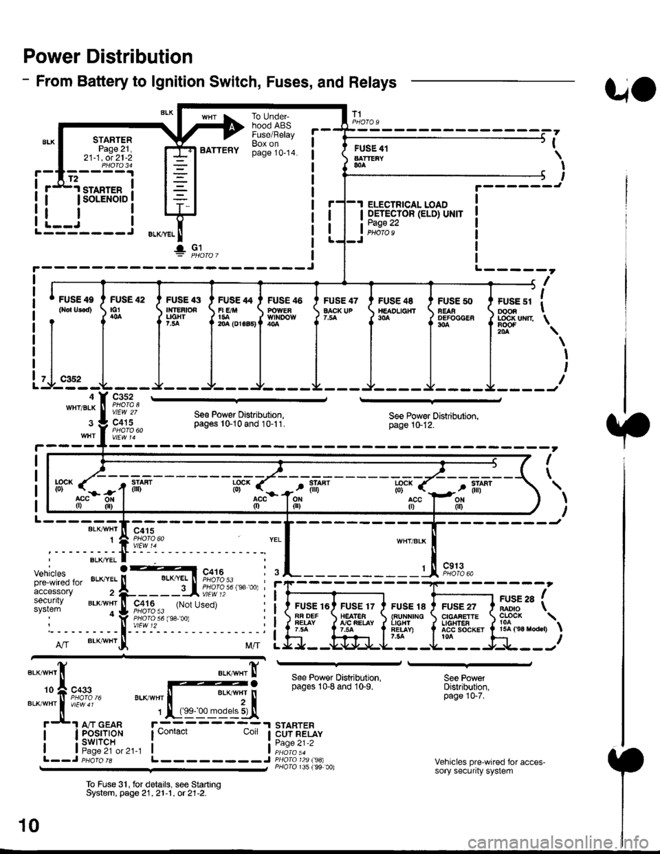
Power Distribution
- From Battery to lgnition Switch, Fuses, and Relays
STARTERPage 21,21-1, ot 21-2
.d1.ro"rr" i
I lsoLENorD I
FUSE 42tG1
BATTERY
To UndeFhood ABSFuse/RelayBox onpage 10-14.
FUSE 47EACK UP
T1
FUSE 41AATTEiY&A
I OETECTOR (ELD) UNIT
tii::.':
UO
PHOfO U
,
I
I
I
t.------J
ELECTRICAL LOAD
i--i rL---- J ELKml
!" Gl
FUSE 4e
0ro{ Urod)FUSE '13Ir|]EAtOAUGHT?.:ta
FUSE 46POWEaWll'IDOW
FUSE /t4
r| E/M1{rA204 (DrGa5)
FUS€ 48TtEADL|a}fT9|'A
FUSE 50NEAAOEFOCGER304
+------, f| ',
I ruse sr I oooa I
J LOC|( uNrr \
il-.4WHT/BLK
Itr '\
\
I
I
I
c352
vlEW 27
c415Se€ Pow€r Distribution,pag6s 10-10 and 10-11.See Power Distribution,page 10-12.
I
\
L------BLK/VI/HT
1
--------Jc415
Vehiclespre-wired foraccessorysecuritysystem
c913PHOTO 6A
FUSE 16AR DEFFEIAY
FUSE 17HEATEA!'/C FEIAY
FUSE 18{RUNNINOL|GHlFET.AY)7.54
FUSE 27CIGAFETTEL|oHTEAACC SOCKET ta
arse ra fBADIO \
?o?"* \15A ('94 raodcr)
ff".acc0)
llL--------J
See Power Distribution,pages 10-8 and 10-9.
STARTERCUT RELAYPage 21-2
P/lolo 135 (99 00)
See PowetDistribution,page 10-7.
Vehicles pre-wired for acces-sory security system
To Fuse 3'|, for delails, see StartrnqSystem, page 21,21-1 , ot 21-2. -
10
Page 1844 of 2189
Power Distributiofl (cont'd)
- From Fuses to Relays and Components
R8€3
5A
tl
tl
PGM.FIMAIN RELAYPag$ 23,24, ot 25PHOfO U
GRY (r8)or Cnl|
Gi Ul|�T
llfllvrtl|€n)
FUSE ,'2
nnx ucms7.ta
I
\
\
I
I
c801PHO|O 5Ac423 r'lPHOTO 58c501PHO|O @vtEw 55
tl
ll
HAZARDWAFNING SWITCHPage 110-6 or 110-8vlEw 32
tt
tl
SRS UNITPags 47PUO|O 70vtt:w 51
r = MaleFemalelerminalsrevgrsed for'99-'00 models
onh no'l Wipsr GRN)
w8r Boar Wipif
'9&'00 Vlhbl.. at?wM frrdocarssy 66ourily eldcn
@
rtYELI *. 1'f
ft?'},' I
l,l m*a" ,,l*i*-
SECURITYSYSTEi' SECURIW SYSTEM
F"ontnlSSto"tott'on' S"ontnl5S]ottott'onr
Gnx I
WHT I
r---l
ll
tl
COMBINATIONWIPER SWITCHPage 92
vlEw 05
10-2
Page 1854 of 2189
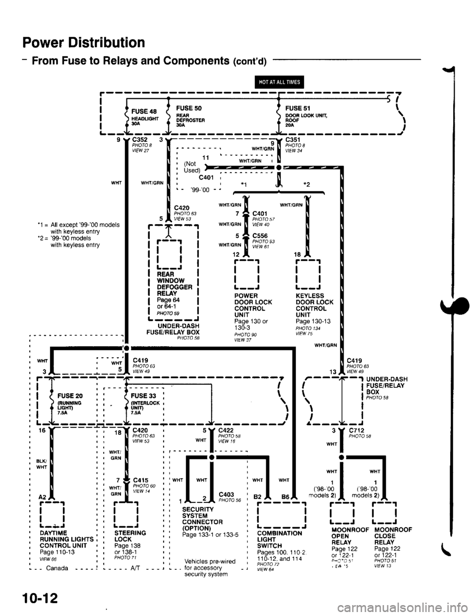
Power Distribution
- From Fuse to Relays and Components (cont'd)
FUSE 48HEAOL|SHT30A
c3s2 3
vtEw 27
WTIT/GFN
FUSF 50FEAFDEFBOSTEF30A
ooon r,ooxuxn \RooF -' I204
I
I
I
I
5t
FusE sr t
9l
;:$*fiit"rl.ru'"'""
I i*il
:::*ffi,
""'_[
tallt r--1 r--1
l-=Ji llll;i'ifr'ilrowi | | | |NEAN
DEFOGGER: L--J L--J
!EuI. ! powen KEYLEss
3g9F I oocin iocx DooR LocKI CONTROL CONTROLPHorobs ! Uttf UN|TL----J ii"j- , "n ^.UNDER-DASH r:d.r ppdro,uFUSETRELAY Box ;;;; "" ,!Fw /); - - - - - - ' - - - - - - - - - - I I P4atasa ;;"; i,
:-;-ry wHr/GFN
: I .-.-.i. -", I '-': :-'I "o''. I l "ott
i
";L____j_lU*?,?"
| .,"Iii;n*
: f'4. ii ;f' ii ,L-.-Ii"?,%' ;f5-"i4.-"'";5-{"'"r'!|L1
:! ! ::! ! :; 3$3i'9,1" r! ! I | | |
i l- l-
- - -
_:-
- ---------1 - - - - - - -
i I r'
- -
T
-
I F$r".',lP,XiI
ii{*"..0 ,' 1;;;il--l l | leox
i! ipp ii liuir'-*i |
')l 'l
l i' r--t-----'-.r--rL--------J- -------t I /---L-I
i
"
l-----l i ::[ir:;?:' i ::[?:+: |
"""1
'*'
i[.iiilr-il[-j,*---]d;1.*-;il;1,
:l I r:l I i: ts6'""?cro* i! ! L--i r--J
i ilr--,.ir...^.._^i I
'rr6-;i."
i: !:lJ',"#,",,*. i i.itc-,tr# Bgg,FooF u-oorinoor' RUNN|NG LrcHrs , ' LocK ; : ; !!gEr_.. ;;,1'y RELAYi cournol^urtr , i pase^138 :: i Swircn- -- Fj.Ti, pase 122, Paoe 110-13 or'138-1 Paoes 100. 110 2 -:Y;^:':;;;''"" :i ;hoi;,; ;: vehicrespre_wired ;!id-?iXioii.' glj:,';: ffl?3;1i,-- canada ----r l----A,/T ---,.-. for accessory -, |;r"*ir" .n 5 vtEvtl 13
10-12
secu.ity system