2000 HONDA CIVIC Speed sensor
[x] Cancel search: Speed sensorPage 1200 of 2189
t-Operation
t
ABS Control Unit
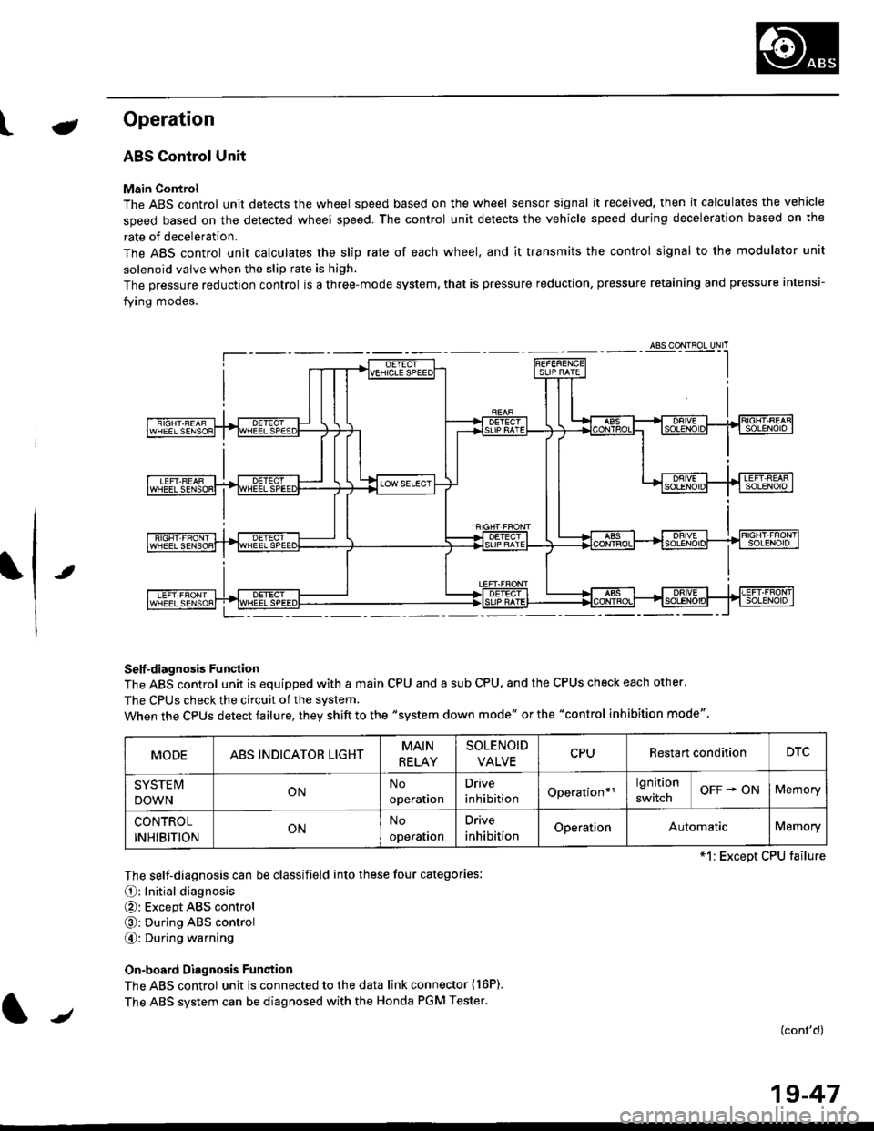
Main Control
The ABS control unit detects the wheel speed based on the wheel sensor signal it received, then it calculates the vehicle
speed based on the detected wheel speed. The control unit detects the vehicle speed during deceleration based on the
rate of deceleration.
The ABS control unit calculates the slip rate of each wheel. and it transmits the control signal to the modulator unit
solenoid valve when the slip rate is high.
The pressure reduction control is a three-mode system, that is pressure reduction, pressure retaining and pressure intensi-
fying modes.
Self -diagnosis Funqtion
The ABS control unit is equipped with a main CPU and a sub CPU, and the CPUS check each other'
The CPUs check the circuit of the svstem.
When the CPUS detect failure, they shift to the "system down mode" or the "control inhibition mode"
The self-diagnosis can be classifield into these four categories:
O: Initial diagnosis
@: Except ABS control
@: During ABS control
@: During warning
On-board Diagnosis Funstion
The ABS control unit is connected to the data link connector {16P).
The ABS system can be diagnosed with the Honda PGM Tester.
(cont'd)
MODEABS INDICATOR LIGHTMAIN
RELAY
SOLENOID
VALVECPURestart conditionDTC
SYSTE IV
DOWNONNo
operation
Drive
inhibitionOperation*rlgnition
switchOFF + ONMemory
CONTROL
INHIBITIONONNo
operalron
Drive
inhibitionOperationAutomaticMemory
*1: Except CPU failure
/
19-47
Page 1202 of 2189
L
Wheel Soeed and Modulator Contlo
t
OUTLETVALVE ON
OFF
INLETVALVE ON
OFF
t\,40ToR
ON
OFF
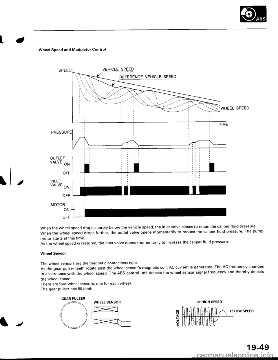
when the wheel speed drops sharply below the vehicle speed, the inlet valve closes to retain the caliper fluid pressure
When the wheel speed drops further, the outlet valve opens momentarily to reduce the caliper fluid pressure. The pump
motor starts at this time.
As the wheel speed is restored, the inlet valve opens momentarily to increase the caliper fluid pressure.
Wheel SensoJ
The wheel sensors are the magnetic contactless type
As the gear pulser teeth rotate past the wheel sensor's magnetic coil, AC current is generated The AC frequency changes
in accordance with the wheel speed. The ABS control unit detects the wheel sensor signal frequency and thereby detects
the wheel speed.
There are four wheel sensors, one for each wheel
The gear pulser has 50 teeth.
EEL SPEED
at LOW SPEEDgl
=o
GEAR PULSEBWHEEL SENSOBat HIGH SPEED
/
19-49
Page 1207 of 2189
Troubleshooting Precautions
ABS Indicator Light
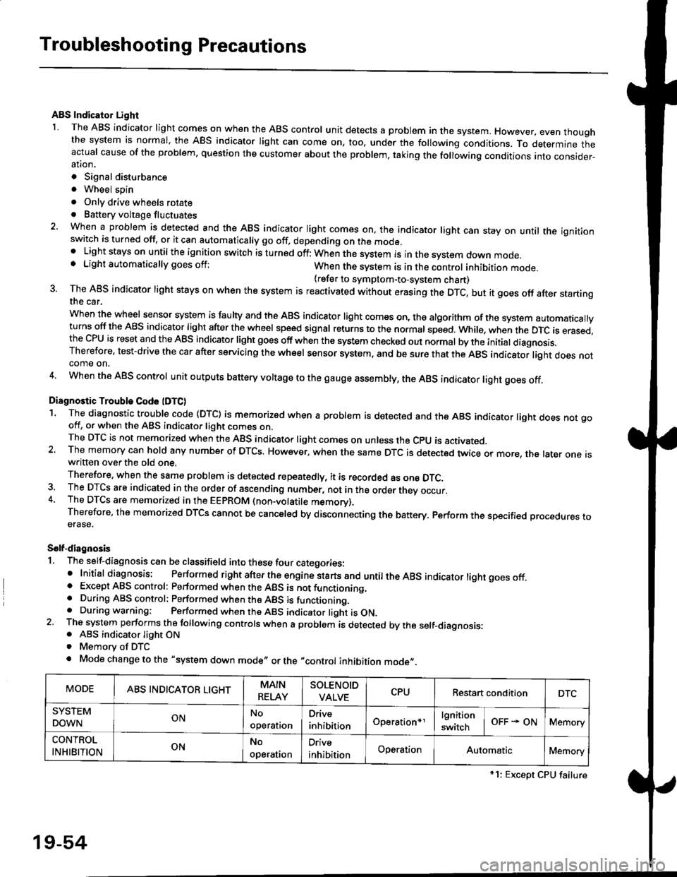
I The ABS indicator light comes on when the ABS control unit detects a problem in the system. However, even thoughthe system is normal, the ABs indicator light can come on, too, under the following conditions. To determine theactual cause of the problem, question the customer about the problem, taking the following conditions into consider-ation.
. Signal disturbance
. Wheel soin
. Only drive wheels rotate. Battery voltage fluctuates
2. When a problem is detected and the ABS indicator light comes on, the indicator light can stay on untat the ignitionswitch is turned off, or it can automatically go off, depending on the mode.. Lightstayson until the ignition switch isturned off;When the system is inthesvstem down mode.o Light automatically goes off:When the system is in the control inhibition mode.(refer to symptom-to-system chart)3 The ABS indicator light stays on when the system is reactivated without erasing the DTC, but it goes off after startingthe car.
when the wheel sensor system is faulty and the ABS indicator light comes on, the algorithm of the system automaticallyturns off the ABS indicator light after the wheel speed signal returns to the normal speed. while, when the DTC is erased,the CPU is reset and the ABS indicator light goes off when the system check€d out normal by the initial diagnosis.Therefore, test-drive the car after servicing the wheel sensor system, and be sure that the ABS indicator light does notcome on.
4. When the ABS control unit outputs battery voltage to the gauge assembty, the ABS indicator light goes off.
Diagnostic Trouble Code (DTC)
1. The diagnostic trouble code (DTC) is memorized when a problem is detected and the ABS indicator light does not gooff, or when the ABS indicator light comes on.The DTC is not memorized when the ABs indicator right comes on unress the cpU is activated.2. The memory can hold any number of DTCs. However, when the same DTc is detected twice or more, the later one iswritten over the old one.
Therefore. when the same problem is detected repeatedly, it is recorded as one DTC.3. The DTCS are indicated in the order of ascending number, not in the order thev occur.4. The DTCS are memorized in the EEpROM {non-volatile memorv}.Therefore, the memorized DTCS cannot be canceled by disconnecting the battery. perform the specified orocedures toerase.
Solf-diagnosis
1. The self-diagnosis can be classifield into these four categories:' Initial diagnosis; Performed right after the engine sta rts and untiltheABs indicator light goes off.o Except ABS control: Performed when the ABS is not functioning,. During ABS control: Performed when the ABS is functioning.. During warning: Performed when the ABS indicator light is ON.2 The system performs the following controls when a problem is detected by the self-diagnosis:. ABS indicator light ON. Memory of DTC
. Mode change to the "system down mode,, or the "control inhibition mode,,.
MODEABS INDICATOR LIGHTMAIN
RELAY
SOLENOID
VALVECPURestart conditionDTC
SYSTEM
DOWNONNo
operal|on
Drive
inhibitionOperation+rlgnition
switchOFF - ONMemory
CONTROL
INHIBITIONONNo
operat|on
Orive
inhibitionOperationAutomaticMemory
*1: Except CPU failure
19-54
Page 1212 of 2189
Le
\.t
CONDITION FOR DETECTION
MANAGEI\,4ENT
FEFERTOPAGEDUNINGABS CONTFOLEXCEPTABS CONTAOL
19-60
19-62
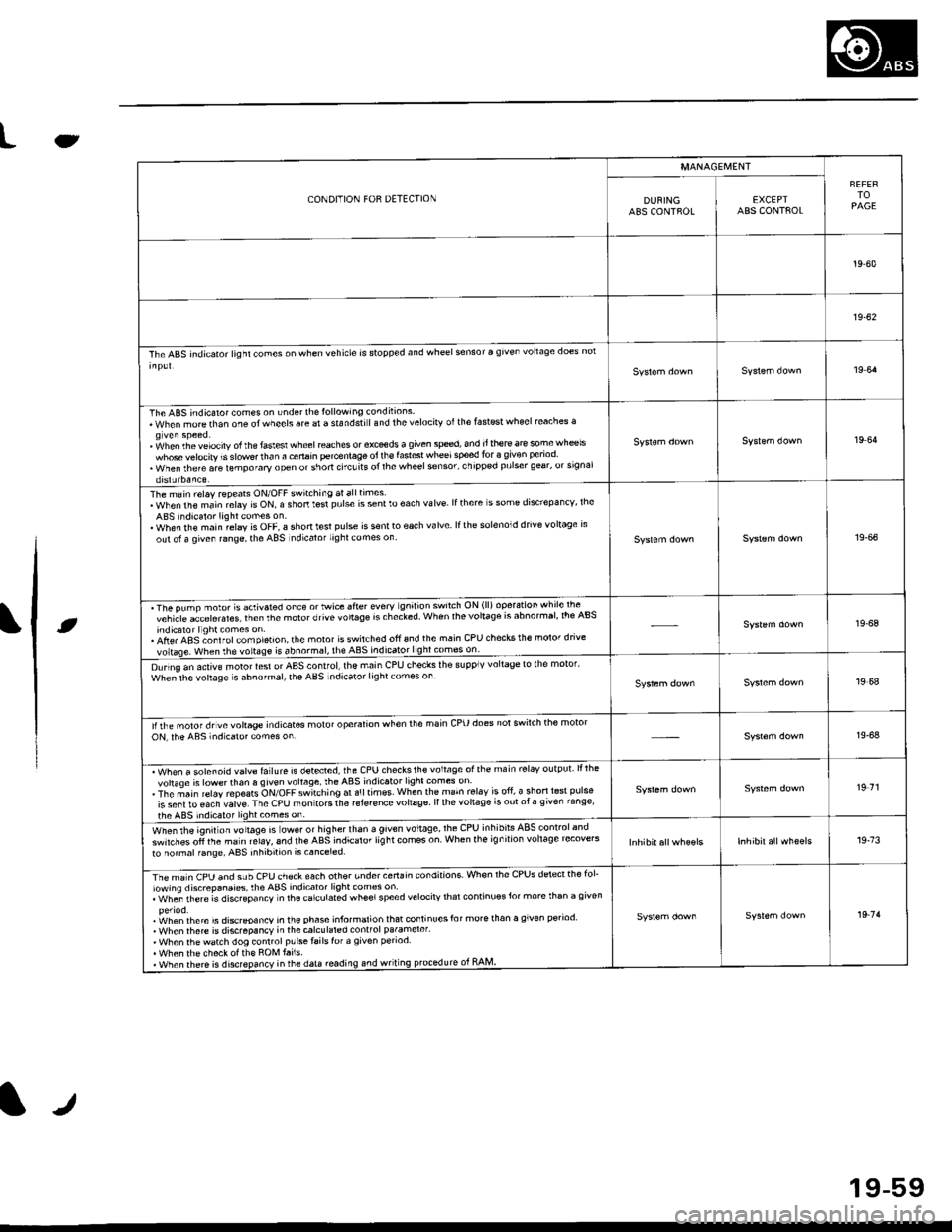
The ABS indicator lighl cones on when vehicle is stopp€d and wheel sensor a given vohaqe does nol
19 64
The ABS indicaror comes on under th€lollowing conditions.When morethan one otwheels are a standstiland thelelocirv otthe fastest wheel reaches a
' fohen th. velocity of the faslesl wheel reaches or exceds a given sped, and it there ar€ somewh@lswhose velocity is slowe.lhan a cenain percenlage oi lh€ fast6t wheelsped for 3 given period. when rhere are lemporary open or short ctcuits ol rhe wheel sonsor' chipp€d pulser gear, orsrgnalorslJrbaaLe
19 64
The main relay repeats ON/OFF switching atalltimes.WhenthemainrelayisON,ashortt$tpulseissentloeachvalve lfthere s some dis'repa ncv, lheABS indicalor lightcomes on.. When rhe main relay is OFF, a shonl€sl pulse is s€nlto each valve lfth6 solenoid drive voltage rsout ol a qiven range, the ABS ndicalor lighl comes on19-66
'The pump nolot s activaled orc€ o' Mrce sfier every gn't'on sw'lch ON (ll) operarion whrle lte -^vchicle acLelerales lrenthemolorotivevo'taSersrhecled When lhevolla96 rs abnormar,lre Absindicaror llghl comes on.. Afte. ABS ;onl rol com pletion, the moror isswitched ofi 6nd the main CPU checks the molor dnvevoltase. when rhe vortase is abnormsl, the ABS indicato49!!!99!:l!:_-
19-68
D!rino an active motor lesl or AAS control,lhe main CPU checks ihe supplv voltage to the motor'whe;lhe vohage s abnofmal, the ABS indicator lightcomes on19,68
lirhe moror drvevoltage indicates molot operalion when the main cPU does notswilch the motoroN, rhe ABs indicaro. comes on19-64
. Wh"" " ".1"".1d ""1r. f"llure is detecred, the CPU checksth€ voltage ofthe main rel6v output lllhevohaqe is lowerthan 6 given vohage, theABS indicator light comes on. The ;ain r€lay repeats ON/OFF switching ar a!ltimss when the main rel.v is ofi, a shorl l6st pulse
is sent ro €ach valve. The CPU mon tors the reJer€nce vohage ll the vohage is out ot a g iven range'
the ABS indic.tor lightcomes on
19 71
wt'",, rt'e lgnitlon rottag" is ower or higherthan a given voltage,lhe CPU inhibils ABSlonlrolandswirches oli the ma in relaY, 6nd the ABS indicaror lig ht com€s on When the ig n ilion vohage recove'sto normal f6ng6, ABS inhibition is canceled.19.73
rimln CpU anO suU CeU ch€ck each other undercertain condnions. Whon rhe CPUS dstectthe fol'lowing discrepanaies, rhe ABS indicator light comss on. whe; rh€re is discGpancv n lhacarculated wheelspeed velocirv thar continuosJor more than a given
.i^/hen rhere is discrcoancv in the ehase informalion lhat continuesfor morerhan a given period' When rhere is discrepancY in thecalculared conlfol pa.amerer'. When thewatch dog conrrolp!lsetailslof a given penod. When th6 checkotth€ ROM tai1s.. when there is disrepancy inrhe data roading.nd wriung prcledurc ot RAM
19 7'l
tr
19-59
Page 1217 of 2189
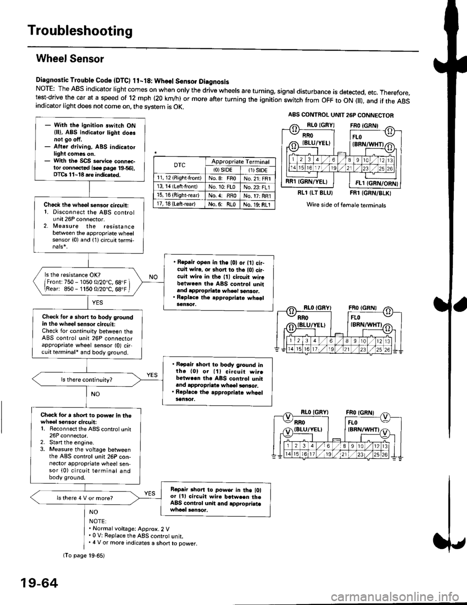
Troubleshooting
Wheel Sensor
Diagnostic Trouble Gode {DTC) ll-18: Wheol S€n3ol DiagnosisNoTE: The ABS indicator light comes on when only the drive wheels are turning, signal disturbance is detected, etc. Therefore,test-drive the car at a speed of 12 mph (20 krn/h) or more after turning the ignition:witch from OFF to ON fll), and if the ABSindicator light does not come on, the svstem is OK.
0TcAppropriate Terminal(0)srDE11) SrD€r 1, 12 (Right-front)No.8: FRoNo.21: FRI13, 14 (Left-front)No. 10: FLoNo.23: FL115, 16 {Right-rear)No. {: RRoNo. 17: RRl17, 18 (Left-rear)No.6: RLoNo. 19: RLI
RLl (LT BLU}FRl (GRN/BLKI
Wire side ol female terminals
NO
NOTE:. Normal voltage: Approx.2 V' 0 V: Replace the ABS controt unit.. 4 V or more indicates a short to power.
A8S CONTROL UNIT 26P CONNECTOR
RRO
IBLU/YELI
RR1 IGRN/YELIFL1 IGRN/ORN}
- With the ignition switch ON{ll), ABS indicator tighr doe.noi go off,- Aftsr driving, ABS indicatotlight comes on.- With the SCS so.vice connac-tor conn€c,ted {soe pege 19-561,DTCs 11-18 a.e indicrted.
Chock lhe wheol sensor ci.cuit:1. Disconnect the ABS controlunit 26P connector.2. lleasure the resistancebetween the appropriate wheelsensor (0) and (1) circuit termi,
. Reprir op€n in the l0l or {0 cir-cuit wiro, or shon to thc {01 cir-cuit wi.o in thc {11 circuit wircbctween ths ABS control unitand approprieto wheel a6nsor.. R.pl.ce th€ epp.opri.te wheal3€nloa.
ls the resistance OK?
/Frontr 750 - 1050 o/20"C, 68.F \\Rear: 850- 1150 O/20.C, 68"F /
Check toru short to body groundin the wheel senso. circuit:Check for continuity between theABS control unit 26P connectorappropriate wheel sensor (0) circuit terminali and body ground.
. Rapair short to body ground inth6 (0) or lll cilcuit wi..bctwa.n th6 ABS control unitand appropdaie whoel lonsor.. Rep|'c6 tho appropriatc whcelsanlor.
Chock tor a sho.t to powe. in thowheel3en3or circuit:1. Reconnect the ABS control unit26P connector,2. Start the engine.3. Measure the voltage betweenthe ABS control unit 26P con-nector appropriate wheel sen-sor (0) circuit terminal andbody ground.
Ropair rhon to powo. in the l0lor lll circuit wire batw.en th€ABS cont.ol unit and .pplopriatawhccl !€naoa,
ls there 4 V or more?
fio page 19-65)
19-64
Page 1486 of 2189

Connector ldentification and Wire Harness Routing
Engine Wire Harness lD16Y5, D16Y8 enginss): '96 - 98 models
Connector or
Torminal
Numbsr of
CavitissLocationConnects toNot€s
c 101c102c103c104c104c105c106c107c108c 109c110c111c112c113c114c115c116cl17c118c119c120cl21
c122c123cl23c124
c125
c127c12Ac129c130c131c132c 133c134c135
c136
c138c139c140c 141c142c 143c144cl44c145c'146cl47
10
1
22
14l4322l0I
2
2
2
2120
3l
14
14
1222
2
2
22
Left side of engine compartmentMiddle of engineMiddle of engineLeft side of engine companmentLeft side of engine compartmentMiddle of engineMiddle of engineMiddle of engineMiddle of engineMiddle of enginefvliddle of engineMiddle of engineMiddle of engineMiddle of engineMiddle of engineMiddle of engineMiddle of engineLeft side of engine compartmentMiddle of engineMiddle of engineMiddle of engineMiddle of engine
Middle of engineMiddle of engineMiddle of engineMiddle of engineMiddle of engineMiddle of engineMiddle of engineMiddle of engineMiddle of engineRight side of engine companmentBehind right kick panelUnder right side of dashUnder riOht side of dashUnder right side of dashUnder right side of dashUnder right side of dashUnder right side of dash
Under right side of dash
Under right side of dash
Middle of engineMiddle ot enginel iddle of engineMiddle of engineMiddle of ongineMiddle of engineLeft side of engine compartmentMiddle of engineMiddle of engineRight side of engine compartmentRight side of engine compartmentRight side of engine compartment
USACanada
Afi
USA
-' (A/r)
Main wire harness (C303)Crankshaft speed fluctuation (CKF) sensorEngine oil pressure switchAlternatorAlternatorNo. 'l fuel injectorNo. 2 fuel injectorNo.3 fuel injectorNo. 4 fuel injectorIAC valveThrottle position (TP) sensorl\4anifold absolute pressure (MAP) sensorIntake air temperature (lAT) sensorPower steering pressure {PSPI switchEVAP purge control solenoid valveJunction connectorJunction conn€ctorVehicle speed sensor {VSS}Countershaft speed sensorEngine coolant temp€rature (ECT) switch ADistributorEngine coolant temperature (ECT) sendingunrtEngine coolant temperature (ECT) sensorPrimary HO2S (sensor'l)Primary HO2S (sensor 1)Back-up light switchLock-up control solenoid valveSecondary HO2S (sensor 2)Mainshaft speed sensorLinear solgnoid valveShift control solsnoid valveStarter solenoidJunction connectorMain wire harnesE (C446)ECM/PCMPCMECMiPCMECM/PCMMain wire harness (C305)
Main wire harness (C305)
Main wire harness (C305)
Knock sensor (KS)IAC valveVTEC solenoid valveVTEC pressure switchEVAP control canister vent shut valveEGR control solenoid valveSecondary gear shaft speed sensorEGR valveEGR valveDrive pulley speed sensorSolenoid connector {CVT)Driven pulley speed sensor
*, (M/T)M/T*" INT\
*, tAtf)
NT:'96 model*,(A,/T):'97 - 98mooets
moqets
M/T
-1 (l,/T)*, (A,/T)-,(4,/T)*1 {M/T)*, (A,/T)*1 (CW)*, (A,T)
T101r102Left side of engine companmentRight side of engine companmentAlternatorUnder-hood fuse/relay boxG 101Middle of engineEngine ground, via engine wire harness
2
*1: Dl6Y5 engine*2: D16Y8 engine*3: D16Y5 (Ay'T), D16Y8 engines
3-16
Page 1488 of 2189
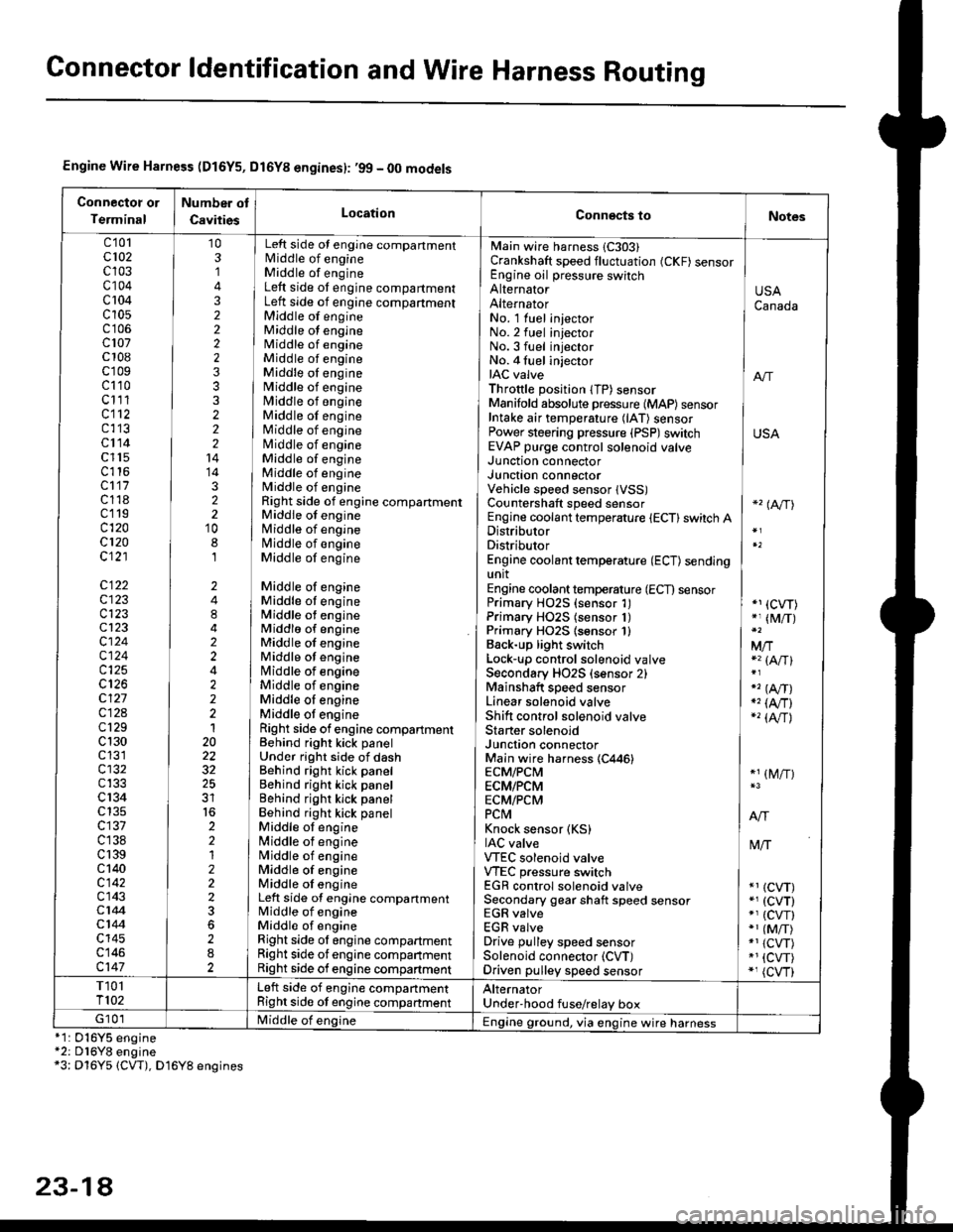
Gonnector ldentification and Wire Harness Routing
Engine Wire Harness (D16Y5, Dl6Yg engines): ,99 - 00 models
Connectot or
Terminal
Number ot
CavitiesLocationConn€cts toNotes
c'101cl02c103c104c 104c10s
c107c 108c'r09c110c111cl12c113cl14c l15c116cl17c118c119c120cl20c121
c122c123c123cl23cl24c124c125
c127c12Ac129c 130c131cl32c133c 134c135c137c138c 139c 140c142c143c144cl44c145c146c147
103,]
322223332221414322'10
8,l
2484224222120
32
2212223
282
No. 1 luel injector INo.2 fuel injectorNo.3 fuel injector ]No. 4 fuel injector iIAC valve I anThrottle position lTP) sensorManifold absolute pressure {MAP) sensor IIntake air temperature (lAT) sensor IPower steering pressure (PSP)switch USAEVAP purge control solenoid valve ]
Main wire harness 1C303)Crankshaft speed fluctuation (CKF) sensorEngine oil pressure switchAlternatorAlternator
Left side ot engine compartmentlvliddle of engineMiddle of engineLeft side ot engine compartmentLeft side of engine compartmentMiddle of engineMiddle ot engineMiddle of engineMiddle of engineMiddle oI engineMiddle of engineMiddle of engineMiddle of engineMiddle of engineNliddle of engineMiddle of engineMiddle of engineMiddle of engineRight side of engine compartmentMiddle of engineMiddle of engineN4iddle of engineMiddle of engine
Middle of engineMiddle ot engineMiddle ot engineMiddlo of engineMiddle of engineMiddle ot enginelrliddle of engineMiddle of engineMiddle oI engineMiddle ot engineRight side of engine compartmenlBehind right kick panelUnder right side of dashBehind right kick panelBehind right kick panelBehind righr kick panelBehind right kick panelMiddle ot engine[,liddle of engineN4iddle of engineMiddle of engineMiddle oI engineLeft side of engine compartmentMiddle of engineMiddle of engineRight side ol engine compartmentRight side of engine companmentRight side of engine compartment
USACanada
Junction connectorJUnct|On COnnectorVehicle speed sensor lVSS)Countershaft speed sensorEngine coolant temperature {ECT} switch ADistributorDistributorEngine coolant temperature (ECT) sendingunitEngine coolant temperature (ECT) sensorPrimary H02S (sensor 1)Primary HO2S (sensor 1)Primary HO2S lsensor 1)Back-up light switchLock'!p control solenoid valveSecondary HO2S (sensor 2)Mainshaft speed sensorLinear solenoid valveShift control solenoid valveStarter solenoidJunction connectorMain wire harness (C446)ECM/PCMECM/PCMECM/PCMPCtvtKnock sensor (KS)IAC valveVTEC solenoid valveVTEC pressure switchEGR control solenoid valveSecondary gear shaft speed sensorEGR valveEGR valveDrive pulley speed sensorSolenoid connector (CVT)Driven pulley speed sensor
*'� (A/TI
*1 (CVT)*, (M/T)
Mfia (A/Tl
" (A,/T)., (4,/r)-'� {AlrJ
*1 (M/T)
tvliT
*1 (CVT)*, (cvT)*' (cw)*1 (MiT)*1 {CVT)*1 {CVT)*, (cvr)
T101T102Left side of engine companmentRight side ot engine companmentAlternatorUnder'hood fuse/relay boxG 101Middle of englne IEngine ground, via engine wire harness*1: 016Y5*2: D16Y8*3: Dl6Y5
engineengine(CW), D16Y8 engines
23-14
Page 1490 of 2189
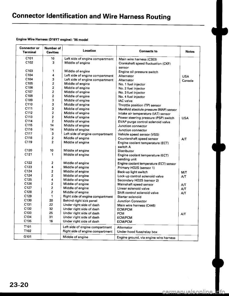
Gonnector ldentification and Wire Harness Routing
Engine Wire Harness {D16Y7 engine}: '96 model
Conneclor or
Terminal
Number ot
CavhiesLocationConnects toNotes
c101
c102
c 103
c104
c104
c105
c'r06
c107
c 108
c 109
c110
c111
c112
c l13
c't14
LttS
cl16
cl17
c118
cl19
c120
c121
c123
c124
c124
c125
c126
c't27
c12a
c129
c130
c131
c132
c133
c134
c135
10
1
4
5
'14
14
10
1
,,
2
2
1
22
31
16
No. 1 fuel injector INo. 2 fuel injector
No. 3 fuel injector INo,4 fuel injector
IAC valve l
Throttle position (TP)sensor IManifold absolute pressure (MAP) sensorIntake ai. temperature (lAT) sensor ]Power steering pressure (PSP) switch I USAEVAP purge control solenoid valve IJunction connector
Junction connector IVehicle speed sensor (VSS) |Countershaft speed sensor AlTEngine coolant temperature (ECT) I
Main wire harness (C303)
Crankshaft speed fluctuation (CKF)
sensor
Engine oil pressure switch
Alternator
Alternator
switch A
Distributor
Engine coolant temperature (ECT)
sending unit
Engine coolant temperature lECT) sensor
Primary H02S (sensor 1)
Back-up light switch
Lock-up control solenoid valve
Secondary HO2S (sensor 2)
Mainshaft speed sensor
Linear solenoid valve
Shift control solenoid valve
Staner solenoid
Junction Connector
Main wire harness {C446)ECM/PCM
PCM
ECM/PCM
ECM/PCM
Left side of engine compartment
Middle of engine
Middle of engine
Left side of engine compartment
Left side of engine compartment
Middle of engine
Middle of engine
Middle of engine
Middle of engine
Middle of engine
Middle of engine
Middle of engine
Middle of engine
Middle of engine
Middle of engine
Middle of engine
Middle of engine
Left side of engine compartment
Middle of engine
Middle of engine
Middle of engine
Middle of engine
Middle of engine
Middle of engine
Middle of engine
Middle of engine
Middle of engine
Middle of engine
Middle of engine
Middle of engine
Right side of engine compartment
Behind right kick panel
Under right side of dash
Under right side of dash
Under right side of dash
Under right side of dash
Under right side of dash
USA
Canada
M/T
AtJ
Afi
T101
T102
Left side of engine compartment
Right side of engine compartment
Alternator
Under-hood fuse/relay box
G101Middle of engineEngine ground, via engine wire harness
23-20