Page 1394 of 2189
Troubleshooting -'99 - 00 Models
Self-diagnosis Function
The heater control panel has a self-diagnosis function.
Running the Self-diagnosis Funqtion
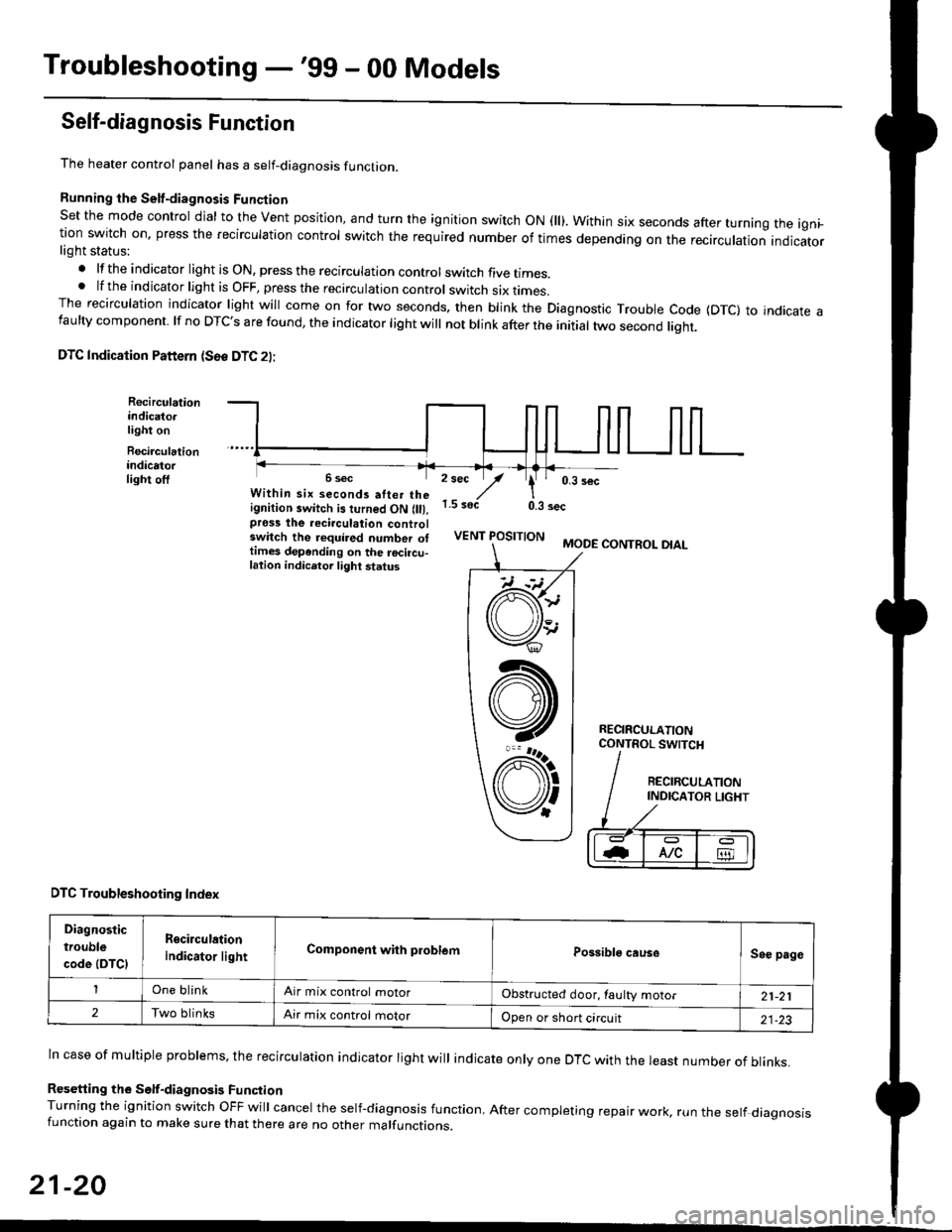
Set the mode control dial to the Vent position, and turn the ignition switch ON fll). Within six seconds after turnang the igni_tion switch on. press the recirculation control switch the required number of times depending on the recirculation indicatorlight status:
.lftheindicatorlightisON,presstherecirculationcontrolswitchfivetrmes.
.lftheindicatorlightisOFF,presstherecirculationcontrol switch six rrmes.The recirculation indicator light will come on for two seconds. then blink the Diagnostic Trouble code {DTc} to indicate afaulty component. lf no DTc's are found, the indicator light will not blink after the initial two second liqht.
DTC Indication Pattern (S6e DTC 2l:
Recirculationindicato.light on
Recirculationindicatorlight off2 sec
,/1.5 soct
' 0,3 secWithin six seconds atter theignition switch is turned ON (lll,pross the recirculation controlswitch the required number ottimes depending on the rocircu-lation indicetor light status
0.3 sec
VENT POSITIONMODE CONTROL DIAL
RECIRCULATIONCONTROL SWTCH
DTC Troubleshooting Index
Diagnostic
trouble
code (DTCI
Rgcirculation
indicator lightComponent with problemPossible causeSee page
One blinkAir mix control motorObstructed door, laulty motor21-21
2Two blinksAir mix control motorOpen or short circuit21-23
ln case of multiple problems, the recirculation indicator light will indicate only one DTc with the least number of blinks.
Resetting the Self-diagnosis FunctionTurning the ignition switch OFF will cancel the self-diagnosis function, After completing repair work, run the setf diagnosisfunction again to make sure that there are no other malfunctions.
21-20
@
At
V'
Page 1404 of 2189
Troubleshooting -'99 - 00 Models
Blower Motor Speed (cont'dl
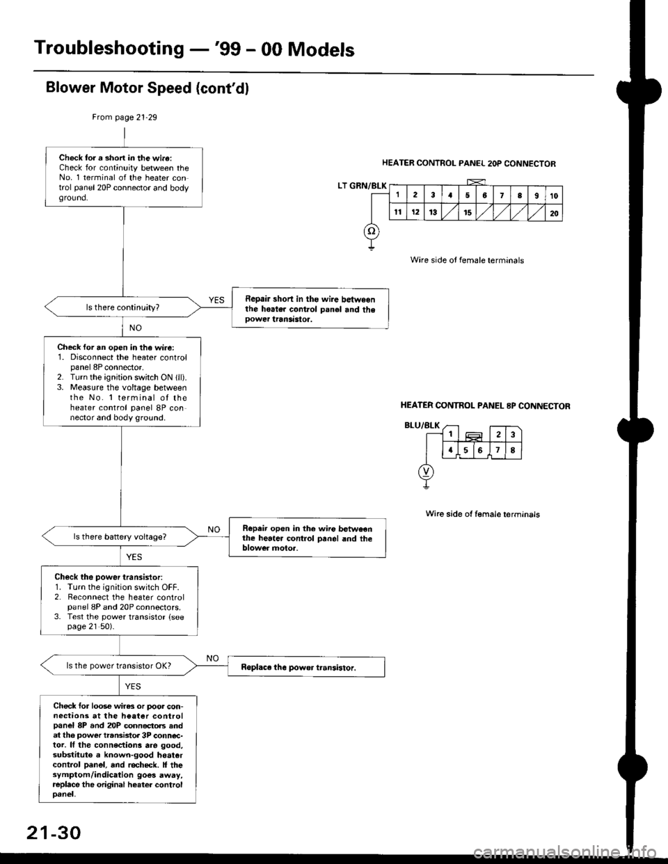
HEATER CONTROL PANEL 2OP CONNECTOR
Wire side oJ female terminals
Wire side ot female terminals
Frcm page 21.29
LT GRN/BLK
Check tor a short in the wi.a:Check for continuity between theNo. 1 terminal of the heater control panel 20P connector and bodyground.
Repair short in ths wire betwsenthe hoater control panel and theoower transastoa.
Check for an open in the wire:1. Disconnect the heater controlpanel 8P connector,2. Turn the ignjtion switch ON 1ll).3. Measure the voltage betweenthe No. 'l terminal of theheater control panel 8P connector and body ground.
Repeir open in the wiio betweenthe heater control panel and theblower motoa.
Check the power transistor:1. Turn the ignition switch OFF.2. Reconnect the heater controlpanel 8P and 20P connectors.3. Test the power transistor {seepage 21 50).
ls the power transistor OK?
Check for loos€ wiras or poor con-nections at the h€at€r controlpanel 8P and 20P connectols andat th6 power transistor 3P conn€c-tor. lf the connections are good,substituto a known-good hoatercontrol panel, and recheck. It thesymptom/indication goes away,replace the original heater controloanel,
HEATER CONTNOL PANEL 8P CONNECTOR
21-30
Page 1410 of 2189
Troubleshooting -'99 - 00 Models
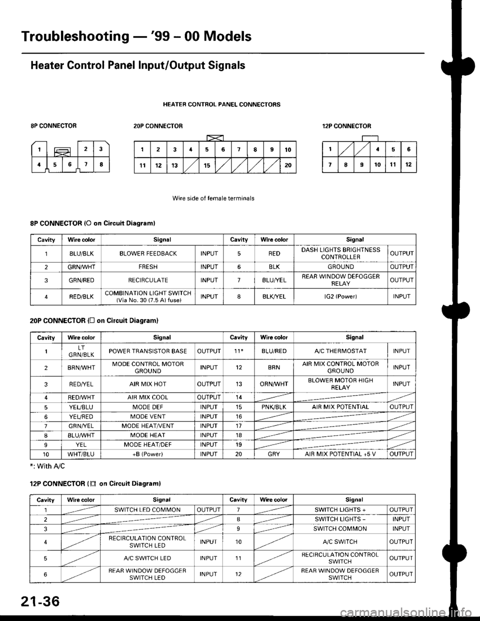
Heater Control Panel Input/Output Signals
HEATER CONTROL PANEL CONNECTORS
8P CONNECTOR2OP CONNECTOR12P CONNECTOR
Wire side of female terminals
8P CONNECTOR (O qn Circuit Diagram)
20P CONNECTOR {D on circuit Diagram}
*: with Ay'c
12P CONNECTOR (tr on Circuit Diagraml
CavityWire colorSignalCavilyWhe colorSignal
BLU/8LKBLOWER FEEDBACKINPUT5REDDASH LIGHTS BRIGHTNESSCONTROLLEROUTPUT
2GRN/lVHTFRESHINPUT6BLKGBOU N DOUTPUT
3GRN/REDRECIRCULATEINPUT7BLU/YELREAR WINDOW DEFOGGERRELAYOUTPUT
4RED/BLKCOMBINATION LIGHT SWITCH(Via No. 30 (7.5 A) fuse)INPUT88LfiELlG2 {Power)INPUT
CavityWire colorSignalCavityWire colorSignal
LTGRN/BLKPOWER TRANSISTOR EASEOUTPUT't1BLU/REDAy'C THERMOSTATINPUT
2BRNMHTMODE CONTROL MOTORGROUNDINPUT12BRNAIR MIX CONTROL MOTORGROU NDINPUT
3RE D/YELAIR MIX HOTOUTPUT13ORNAA/HTBLOWER MOTOR HIGHRELAYINPUT
RED,ryvHIAIR MIX COOLOUTPUT14
5YEUBLUMODE DEFINPUTPN K,/BLKAIR MIX POTENTIALOUTPUT
6YEUREDMODE VENTINPUT16
7GRNI/ELMODE HEAT/r'ENTINPUT11
IBLUAVHTMODE HEATINPUT18
9YELMODE HEAT/DEFINPUT19
10WHT/BLU+B (Power)INPUT20GRYAIR MIX POTENTIAL +5 VOUTPUT
CavityWilecolorSignalCavityWi.e cololSignal
lSWITCH LED COMMONOUTPUT1SWITCH LIGHTS +OUTPUT
2ISWITCH LIGHTS -INPUT
39SWITCH COMMONINPUT
4RECIRCULATION CONTROLSWITCH LEDINPUT10A,/C SWITCHOUTPUT
5A./C SWITCH LEDINPUT11RECIRCULATION CONTROLSWITCHOUTPUT
6REAR WINDOW DEFOGGERSWITCH LEDINPUT12REAR WINDOW DEFOGGEBSWITCHOUTPUT
21-36
Page 1424 of 2189
Mode Control SwitchPower Transistor
Test -'96 - 98 Models
Check for continuity between the terminals accordinq tothe table below.
Terminal
Position't071
Heato-o
HeaVDefo---o
Defo--o
VentG-o
HeaVVento--o
1
;l t
4
789
21-50
Test -'99 - 00 Models
1. Disconnsct the 3P connector from the oower tran-stsror.
2, Carefully release the lock tab on the No. 2 terminal inthe 3P connector, then remove the terminal and insu-late it from body glound.
Connect a 1.2 - 3.4 W bulb between the No. 1 andthe No. 2 cavity on the 3P connector.
Reconnect the 3P connector to the power translstor.
Turn the ignition switch ON fll), and check that theblower motor runs.
12V 1.2-3,1W
No. 1 laLU/aLK)
Page 1425 of 2189
Air Conditioning
Speciaf Tools ......'.....' 22-2
f f f ustrated f ndex ......................... ".......' 22-3
Wiring/Connector Locations'.........'.... 22'4
Description
Outfine ............ .......22-s
Circuit Diagram
'96 - 98 Models ......"..........".......'.... 22-6
'99 Modef """""""' 22-7
Troubleshooting
Symptom Chart ".'......""................. 22-8
Flowcharts
Condenser Fan .........".................,..'. 22-9
Compressor .....""" 22-12
A/C System .........'.22'17
A/C Thermostat
Test ........'.......' """'22'21
Relays
Test ....."'......... ..""'22-21
A/C Service Tips and Precautions ......22-22
A/C System Torque Specifications '...22-23
A/C System Service
Performance Test ... '."......... ".... ....'..22-24
Pressure Test Chart .................. .... "' 22-26
Recovery ...".........," 22-27
Evaporator
Replacement .....",' 22'24
Overhauf .....-.....""' 22'29
Compressor {SANDEN}
Repf acement ......'.' 22-30
fffustrated fndex ......"..................'.... 22'32
Cf utch Inspection ......... "............ ...... 22-33
Clutch Overhau I ........................ ....... 22-34
Thermal Protector Replacement .... 22-36
Relief Valve Replacement ......'..."". 22-36
Compressor (DENSO)
Repfacement ..""',' 22-37
lf lustrated Index ............................... 22-39
Clutch lnspection ............."'...... "'.... 22-40
Cf utch Overhaul .....................'......... 22-41
Ref ief Valve Replacement'..'......"'.. 22-42
A/C Compressor Belt
Adiustment ............22'43
Condenser
Repfacement .......,,22'44
A/C System Service
Evacuation ...,,,.......22-45
Charging '..........--'..22'46
Leak rest """""""'22-46
Page 1440 of 2189
Troubleshooting
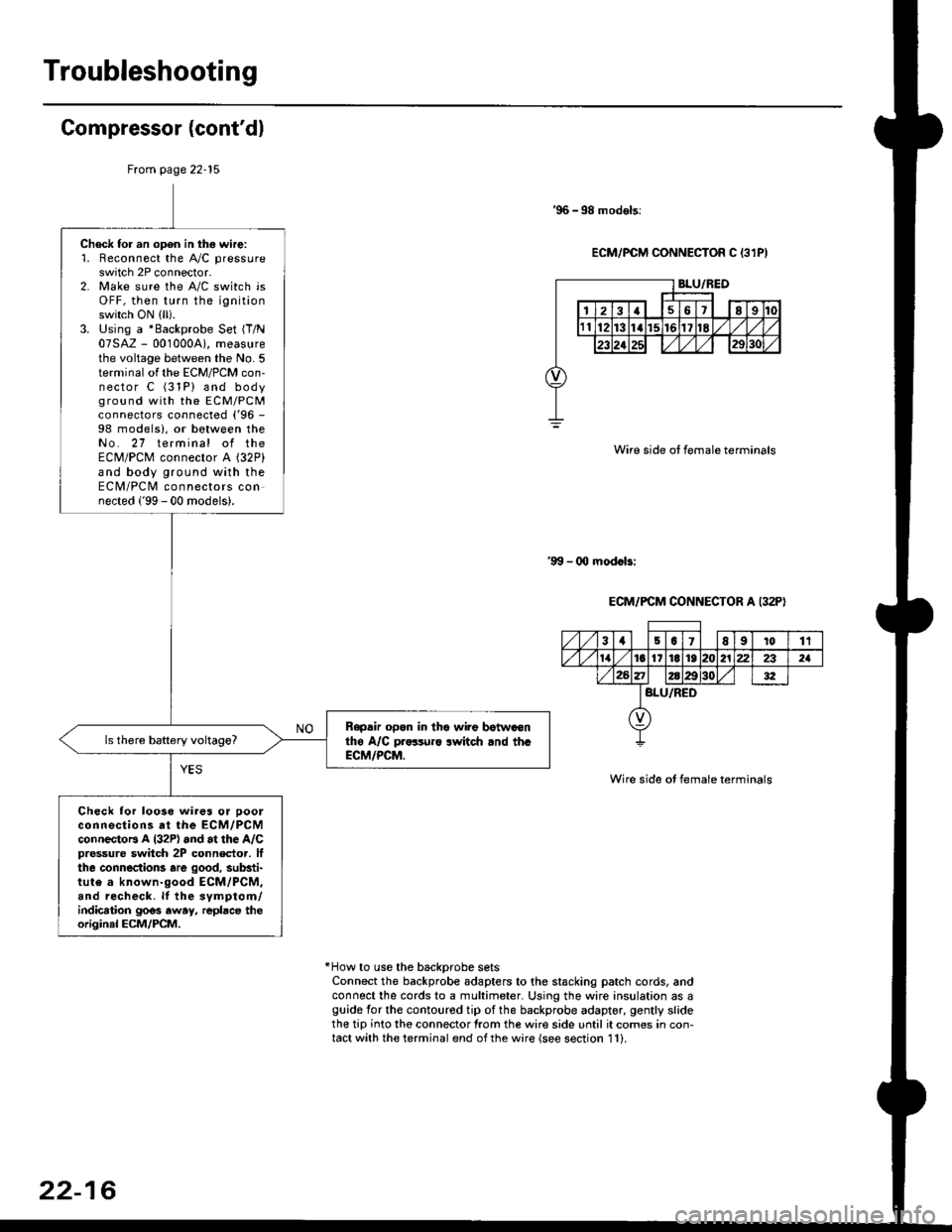
Gompressor (cont'dl
'96 -98 models:
ECM/PCM CONNECTOR C 13lPI
Wire side ot female terminals
'9!t - 00 mod.bi
ECM/PCM CONNECTOR A I32P)
Wire side ot female terminals
*How to use the backprobe setsConnect the backprobe adapters to the stacking patch cords, andconnect the cords to a multimeter. Using the wire insulation as aguide for the contoured tip of the backprobe adapter, gently slidethe tip into the connector from the wire side until it comes in con-tact with the terminal end ofthe wire {see section 11}.
From page 22-15
Check for an open in thg wire:'1. Reconnect the A"/C pressure
switch 2P connector.2. Make sure the A/C switch isOFF, then turn the ignitionswitch ON (ll).
3. Using a *Backprobe Set {T/N07SAZ - 001000A), measurethe voltage between the No. 5terminal of the ECM/PCM con-nector C (31P) and bodyground with the EcM/PcMconnectors connected ('96 -
98 models), or between theNo. 27 terminal of theECM/PCM connector A (32P)
and body ground with theECM/PCM connectors connected ('99 - 00 models).
Rapdir open in tho wi?e botwaonthe A/C pr..-ruro lwitch rnd th.ECM/PCM.
Check lor loo3e wires or ooolconnections at the ECM/PCMconnectoB A l32P) and at the A/Cpressure switch 2P connector, lfthe connections are good, substi-tute a known-good ECM/PCM,and recheck. lf the svmptom/indication goos away, repbce theoriginal ECM/PCM.
31501E91011
tat6l11E1921222321
BLU/RED
22-16
Page 1442 of 2189
Troubleshooting
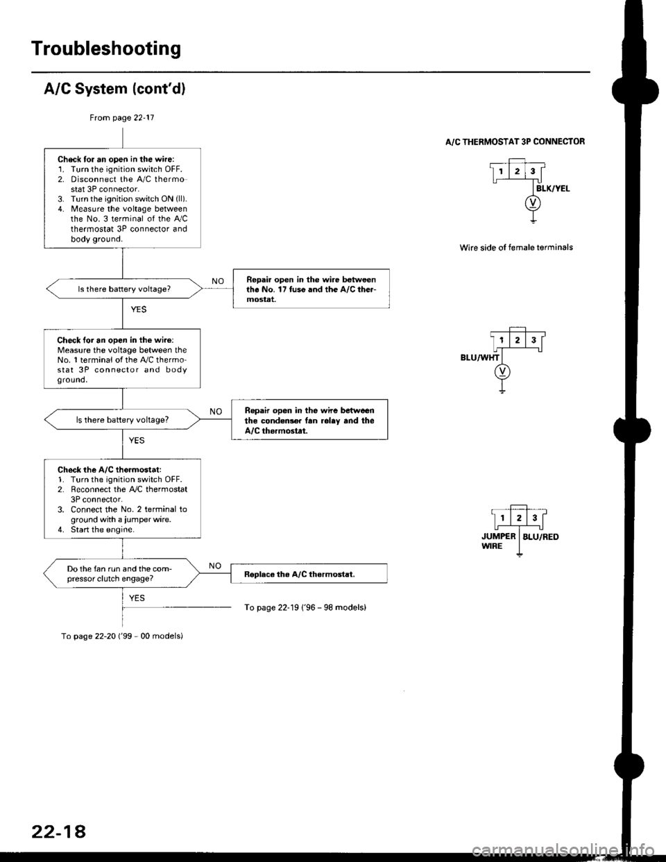
A/C System (cont'd)
From page 22-11
. _Ff,, __
I11213[
,r,il*"-T",-.r-'..owrRE I
To page 22-19 1'96 - 98 models)
A/C THERMOSTAT 3P CONNECTOR
Wire side oI female terminals
Check tor an open in the wire:1. Turn the ignition switch OFF.2. Disconnect the A/C thermostat 3P connector.3. Turn the ignition switch ON (ll).
4. Measure the voltage betweenthe No. 3 terminal of the Ay'Cthermostat 3P connector andbody ground.
Repai. open in the wire betweentho No. 17 tuso and the A/C the.-mostat.
Check loi an open in the wi.e:Measure the voltage between theNo. 1 terminal of the A,/C thermostat 3P connector and bodyground,
Ropair open in the wire betwoenthe condedlo. lan rolay and theA/C thormostat.
ls there battery voltage?
Check the A/C th6rmostat:1. Turn the ignition switch OFF.2. Reconnect the A,/C thermostat3P connector.3. Connect the No. 2 terminal toground with a iumperwire.4. Start the engine.
Do the fan run and the com-pressor clutch engage?
To page 22-20 ('99 - 00 models)
22-18
Page 1448 of 2189
A/C System Service
Performance Test
The performance test will help determine if the air con-
ditioner system is operating within specifications.
Use only service equipment that is U.L.-listed and is cer-
tified to meet the reouirements of SAE J2210 to remove
HFC-134a (R-134a) from the air conditioner system.
CAUTION: Exposure to air conditionor rofrigerant and
lubricant vapor or mist can irrilalo €yes, nose and
throat. Avoid breathing tho air conditioner rstrigerrnt
and lubricant vapor or mist,
lf accidental system discharge occurs, ventilate work
area before resuming service.
R-134a service equipment or vehicle air conditioner sys-
tems should not be pressure tested or leak tested with
compressed air.
@ some mixtur$ of air and R-134a have been
shown lo b9 combustible rt glgvatad pr€ssur63 and can
resull in tire 01 oxplosion causing inlury ot property
damage. Never uao compre33ed air to pressure t99t R-
134a ssrvico 6quipmsnt or vohicla air conditioner sys-
tems.
Additional health and safety information may be obtained
from the refrigerant and lubricant manufacturers.
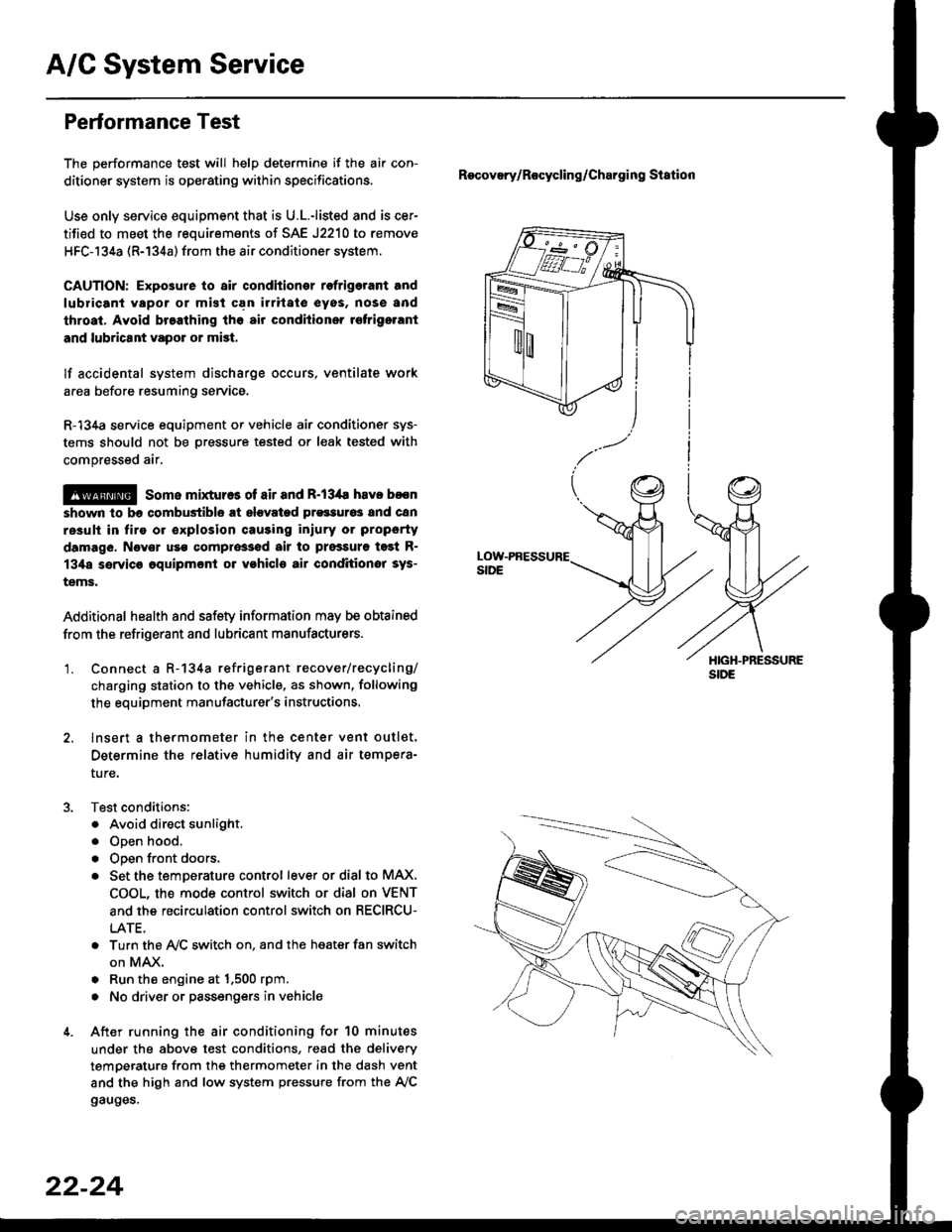
'1. Connect a R-134a refrigerant recover/recycling/
charging station to the vehicle, as shown, following
the equipment manufacturer's instructions.
2. lnsert a thermometer in the center vent outlet.
Determine the relative humidity and air tempera-
ture,
Test conditions:
. Avoid direct sunlight.
. Open hood.
. Open front doors.
. Set the temDerature control lever or dial to MAX,
COOL, the mode control switch or dial on VENT
and the recirculation control switch on RECIRCU-
LATE.
. Turn the A,/C switch on. and the heater fan switch
on MAX.
. Run the engine at 1,500 rpm.
. No driver or passengers in vehicle
After running the air conditioning for 10 minutes
under the above test conditions, read the delivery
temperature from the thermometer in the dash vent
and the high and low system pressure from the A,/C
gauges.
Recovery/Rocycling/Charging Station
22-24