Page 1540 of 2189
Power Distribution
Circuit ldentification (cont'd)
IGN|T 0N SWTTCH (ACo)lFrom page 23-69)
*3 (or PNn -
Anernal0rVSS
HO2SEVAP conlrol canister vent shr,,l vafoeEVAP Flrge conrol so enord valveECM/PCM"
Back-!p lighls
SRS unri (VB)
i.1 :'96,98 modesr.2 : 99 mode*3 :GRY ('96-97 models):GRN (98'00 models)
sLrwHT+ Ft"t:itJY;i
BLI{WHT -}rcutcwt.,
BLKr'r{HT - Chargir! syslem trghl
InteEalei conLol unft
Shin lock soenod I r!/r\lnleiock mnlrol un I J '- '
Galge ass€mblySRS indicalor lighlABS indicrtor lghlA/Igear posilion nd€lorl d,mmino qrcu,luru6e notcaoa ) -
Inlegraled conlrcl un t
Windshield wiper molor
GRN,B-< ........- ImeEaleo cortolull| (viawndshieLd wi9el swllci)- wrrdsi erd washer .nolor(Via swrn)
Accessory power sockel (ACC)
oplioial conneclor (Acc)
Audio unil
UNDEF.DASH FUSE/REtAY BOX
No 1s (7 sA)
POWERWINDOW RELAY(To page 23-71 )
N0.25 (7.5A)
GBN/OF -- Moolroolopel relay- MOOlrOOldOSe relav
(Fusoirelay box sockel)
YEL-
(Fuse/relay box socl€l)
Y_ *,n,,*
23-70
Page 1847 of 2189

'1 = '96 D16Y8 engine: All coupes'97 D16Y7 engine: California Coupe, California Sedan LX'97 D16YB engine: All coupes, California Sedan'98100 models: All except D1685-.t UNDER-DASHI
I
\
'--1 $NEGRATED
| !s$il:'Ptlofo avtEw 67
c42'lPHO|O 63vlEW 50
ct01
vtEw28
FUSE/RELAYBOX
\
I
T
D16Y8
13
c568
ELKAYTIT
BLKAVHT
1
143
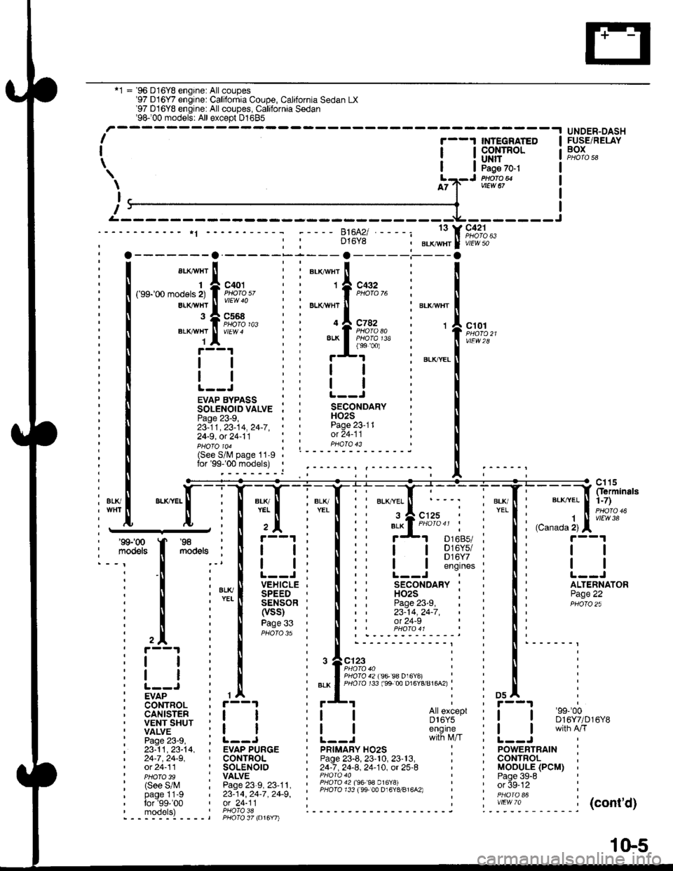
EVAP BYPASS : :SOLENOIDVALVE . ,Page 23-9,23-11,23-14,24-7,' '
24-9, ot 24-11
H02SPage 23-11ot 24-11pHoTolo4 ; ; PHoTo 43(See S/lV page 11-9lor'99-'00 models) ,
i1[
":"[-lT:T
l+Tli'::f;:r i"'{' l;;;]fip;:
I Fs'[
**,
I il i I ii !-l s];$:i i Ii t--l
i ! i'*[ iEi.;*Ti lii
'fl*-i
i li itqii-*
i l il[l?ti
lii iiii;:" i:li
i trr i I i.r^.:.'.'.'i::::;j i !' i
: i i , I i ,+e;::"," i : ! i
itI
i! | i | :".*lfigi3li;ts's"";:tg;u'u^.i : ! :
iv7"-- : rA : *'I i i osl :
; CoNTBOL , r--1
i liiit- i i_j i i_j #s,{;'i' i [__j
ffnih'*'
i 23:11,23-t4, , EVAP PURGE I pRtMARy Ho2s : ' powERTRAtN :| 24-7,24-9, ' CONTFOL ; Page 23-8, 23'10, 23'13, , ; CONTROL ,' ot 24-11 ' SOLENOIO , 24-7 .24-8. 24-10. ot 25-8 ' , MOOULE (PCM) ,' pHoTo 3s : VALVE I PHoro 40 ' ' Paqe 39-8 '
| (see s/M : Pase23-s,23'11, : ii3l311l l3;ll Pl?191,.,"^,, : ' orSe-12 :
' PHoTo 39 I vALvE | ' Paqe 39-6
: (See S/M : Page 23-9, 23'11. ' lHqI94?199 99 0.16Y!i - i ' or 5g-tz :i bi-gllt-g i zs:tq, zc-i, zc-g', ' PHoro 733 ree 00 D16Y8/816A2) i '. in6i "i i
:':1T:9' ',91"?i'l; i------ ------j ".-':-*-'1. -----j(cont'd)- - - -::-:-l - - - - t PHO\O 37 to16Y7l
1(}5
Page 1889 of 2189
![HONDA CIVIC 2000 6.G Workshop Manual POWERTRAIN TFUSE 15AtTEii|AtOf, ^ -aPsE|{aon see Fowert5a ^ Distribution,99coldary---]-l-"jt=-.iHO2S iinBt
E*o,*. !CONTROL IMODULE I(PCMoTECM) :i,l,llouu riI
\T,T]KDT4
WHT/NEDBLKAVHT
1
T
t
WHI/FED
I HONDA CIVIC 2000 6.G Workshop Manual POWERTRAIN TFUSE 15AtTEii|AtOf, ^ -aPsE|{aon see Fowert5a ^ Distribution,99coldary---]-l-"jt=-.iHO2S iinBt
E*o,*. !CONTROL IMODULE I(PCMoTECM) :i,l,llouu riI
\T,T]KDT4
WHT/NEDBLKAVHT
1
T
t
WHI/FED
I](/manual-img/13/6068/w960_6068-1888.png)
POWERTRAIN TFUSE 15AtTEii|AtOf, ^ -aPsE|{aon see Fowert5a ^ Distribution,99coldary---]-l-"jt='-.iHO2S iinBt
E*o,*. !CONTROL IMODULE I(PCMoTECM) :'i,l,llouu riI
\T,T]KDT4
WHT/NEDBLKAVHT
1
T
t
WHI/FED
IT GFN
c130Oermlnals1n0)
vtEw 52
')------------6;ffii----F'�di---:-- ----Ttgy.:!-
{ Strff' .'Sffi"? .uoFo?,* | su #33nno' ruo'ffiJ,. srouno i6is-*' #;,"1"-* ' canistqvent sotenoid l":iiEt$'[i,
i ffii$J' *H*"n' i :3Hl'5'* varvaclntror,llg'r+,.'
I . -__-,__-SJECM)fL------ Prloro a6
t
UNDER.DASHFUSE/RELAYBOXPHOTA 58
BLKAVHT
1I'j
c101
vtEw 2a
_{
rn+5-m
. c115, Oermlnals,'t-71
I vtEw 38
c401
c568
VIEW 4
ALKAVHT
BLKAVHT
,l
See Pow€rDistribution,page 10.5.
EVAPORATIVEEMtSStON(EVAP) PURGECONTROLSOLENOIDVALVE
EVAPORA. 'TIVEEMtSStON '
(EVAP) :BYPASS iSOLENOID ,VALVEEvaponn- 2
TIVEEMtSStON(EVAP)CONTROLCANISTERVENT SHUTVALVEPHATO 39
c125
BLU
1
BFN/BLK
'97 model:Calilornia Coupe,Calilornia Sedan LX'98 modei: all
c568
c401
c131
vlEw 59
Ses GrourdDisMbdion,pag€ 14-1.
NEO/YELBLKNVHT
D13A5
FED,^VEL
A15
LT GFNAIVHTT1
G101PHO|Q 33M8
BIK/YEL
r+l
23-9
Page 1891 of 2189
![HONDA CIVIC 2000 6.G Workshop Manual t)
POWERTRAINorENGINECONTROLMODULE(PCM or ECM)
BLKryVHT
fFUSE 15AL1EA|{A]OAsP sExsoa7.54See PowerDistribution,page 10-5.
UNDER.DASHFUSE/RELAYBOX
t\-I Secondary! HO2S input, (sf,o2sl-------
- ,.-"., -^ HONDA CIVIC 2000 6.G Workshop Manual t)
POWERTRAINorENGINECONTROLMODULE(PCM or ECM)
BLKryVHT
fFUSE 15AL1EA|{A]OAsP sExsoa7.54See PowerDistribution,page 10-5.
UNDER.DASHFUSE/RELAYBOX
t\-I Secondary! HO2S input, (sf,o2sl-------
- ,.-"., -^](/manual-img/13/6068/w960_6068-1890.png)
t)
POWERTRAINorENGINECONTROLMODULE(PCM or ECM)
BLKryVHT
fFUSE 15AL1EA|{A]OAsP sExsoa7.54See PowerDistribution,page 10-5.
UNDER.DASHFUSE/RELAYBOX
t\-I Secondary! HO2S input, (sf,o2sl-------
- ,.-"., -^,o"::.f=_
rtl
ll er-x'wnr
g A crer
""",".--*'i-"fj*"
c432
c7a2
-l--
:
$i
see Power
SECOND- F rl EVAPORATIVE ' f-tl-l EVAPORA- ;ARY I I I EMISSION 'I I ITIVE
8iiE,R I ltt l !'JiiABi*"'il ltt l Et,i"'J""sENsoR I Jll I soleHoro 'l )ll I i9x1661
!t"93:t IJJ vs!:", iLLl !Ailf*'",,
: I 'l"u.t
".*,^,'"rf I ,----j I l';i";?'*
2 J:--;t, C432 ll 96 model: all Coupesptlofo /6 i 97 model a
coupes,
BLKI"V!/HT
--1"r", 'Y :t f iiiv!3 Y iiol-o ao
onr.r wxr I I ll catrfornra Sedan ll 9 g c49 !s8 mocJr, iri I a il!9.!a^5?
""""._l**t' ,L-
r I i,,o"n,n",l "f,",ul,,
-"-.1,=l
;^[::Ttn*- I i I
""1
,
+ g:%,, *"[
il I :D13 A A5A A15 A , A2gA 428 |'-----=,-- -=-7-tsHo2sc) tso2sHTci {Pcs) | {vs!,) (2wBs)Sensor Secondary EVAP purge ' EVAP control EVAP bypassground HO2S hedter controisolenoid : canister vent solenoidt control valve control , shut valve valve controlt , conkglttb------
BLKAA/HT
BLKAVHT
1
c401
c568
BLKTIVHT
BIK
FED1
Distribution, '
page 10-5. :
, BLK' YEL
SHUT BLU
(Terminals 1-10)
vtEw 52
! Ii{:',+'i":
II
23-11
Page 1894 of 2189
PGM-FI (All '96-'98 Models except D1685; 'g$.'00 D16y5 with M/T)
- D16Y5 engine (cont'd)
r-------1POWERTRAINOJENGINECONTROLMODULE(PCM or ECM)
c125
---------1
FUSE 15
$t"t!ilS8" see Powert.5A - Distribution,page 10-5.
UNDER-DASHFUSE/RELAYBOXSecondaryH02Sanput(sH02s)
D14 I'
,n"r,"ao I
rtr
lt I
I
i,tjclt5(Ierminals'1-7]T I 1
vtEw 3a
HI
lffiq,m
,.ul
- '' :
3A-3uA---g'A--i--**----f'I :(sro2sc) (so2sHrc) (pcs) , ryse -"-*"i - l! 39Y.E!:
;:m AA8r"y- rvffi's" i euo8S:noo' E\"L'�Yssl 'iH;in';'
hearer sorenoid : :ill*',":* ;:fl'".t"* iiF!ii"te'-control valv6 control I controt ___-- ll?|Et",".,:
T
$
See Pow6rDistribution,page 10-5.
BLK,/li!/HT
BLK,\II/HT
1
c401
c568
EVAPORATIVE :EM|SSTON ;(EVAP) PUBGE .CONTROLSOLENOIDVALVEPHOfO 38
EVAPORA.TIVEEMISSION(EVAP)CONTROLCANISTEFVENTSHUTVALVE
EVAPORA-TIVEEMtSStON(EVAP)BYPASSSOLENOIDVALVE
(See S/Mpage | 1-9for'99-'00models)
'98-'�00
mooets
c568
c4o1 :
PHO|A A5vlEW 59
11 g Ct31
See GroundDistribution,pag€ 14-1.
Y
I
anver.x
b9^
23-14
Page 1906 of 2189

--.I POWERTRAt lor I I rusers i oasx
I ! EtR'+[i. i ) el'stwg^ seepower i[EiFi
*'tr
_____:l*.'
#l:_l::i\--
$11*"1
;f;,_,
,, lhtEffe. i l giTr**- Bi:,ffiilsr iI Secondary
i- - - - - - - - :84 - - - i fis"'!r"'**,,i *#i5
-''!
lil$iiiE- ilt5t--- -oii,ib"t;". lEb;I S.econdary | iFCrrr-o, eCn11l I - page 1O-5. I Fa6io sa
_,a"3,____ j ",E"-o t" y;rjrt...
A23 Y BLKrt!/Hr I v4d5o
[t] |
:iT[r""-l
*.--il''""'
:xl f''i-'l !trLw18 I .Ar*
Seecround : GRNBLKI BLK\"HI I FEoYELI LT GRN wttr
ii.ir'r;U: !
1 [
*"=[:-{r**,,"'^"'l
Fi{f},ff' ".**n,t
"-#::"""_
! 1""'"*..!.--":i^."^ I I lfuri+ta:"
| * | ,"",1*--".Jrr*,, ,l ,l LSn*ur,"
Ll _, ffii** $
w**-
ry
*il
I
*i{tu
Page143. : It I I i - Yi',,,u,
[!l
",,,
,F"
|
"."":.tun't
+ F,'"%*
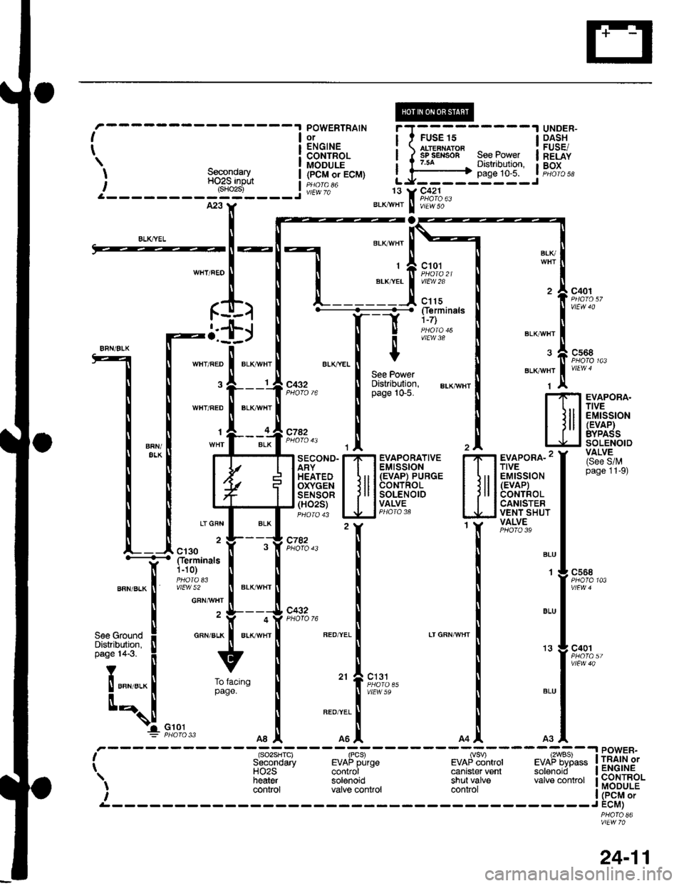
----, (sO2sHTc) (PCS) (vSV) L2WBS)i Secondary EVAP pufge EVAP control EVAP bypass !r. HO2S control canister venl solenoid Itt heater solenoid shut valve valve control I! control valve control controli *'-- |.E------ ----J
13 g c401
POWER.TRAIN orENGINECONTROLMODULE(PCM orECM)
vtEW 70
24-11
Page 1953 of 2189

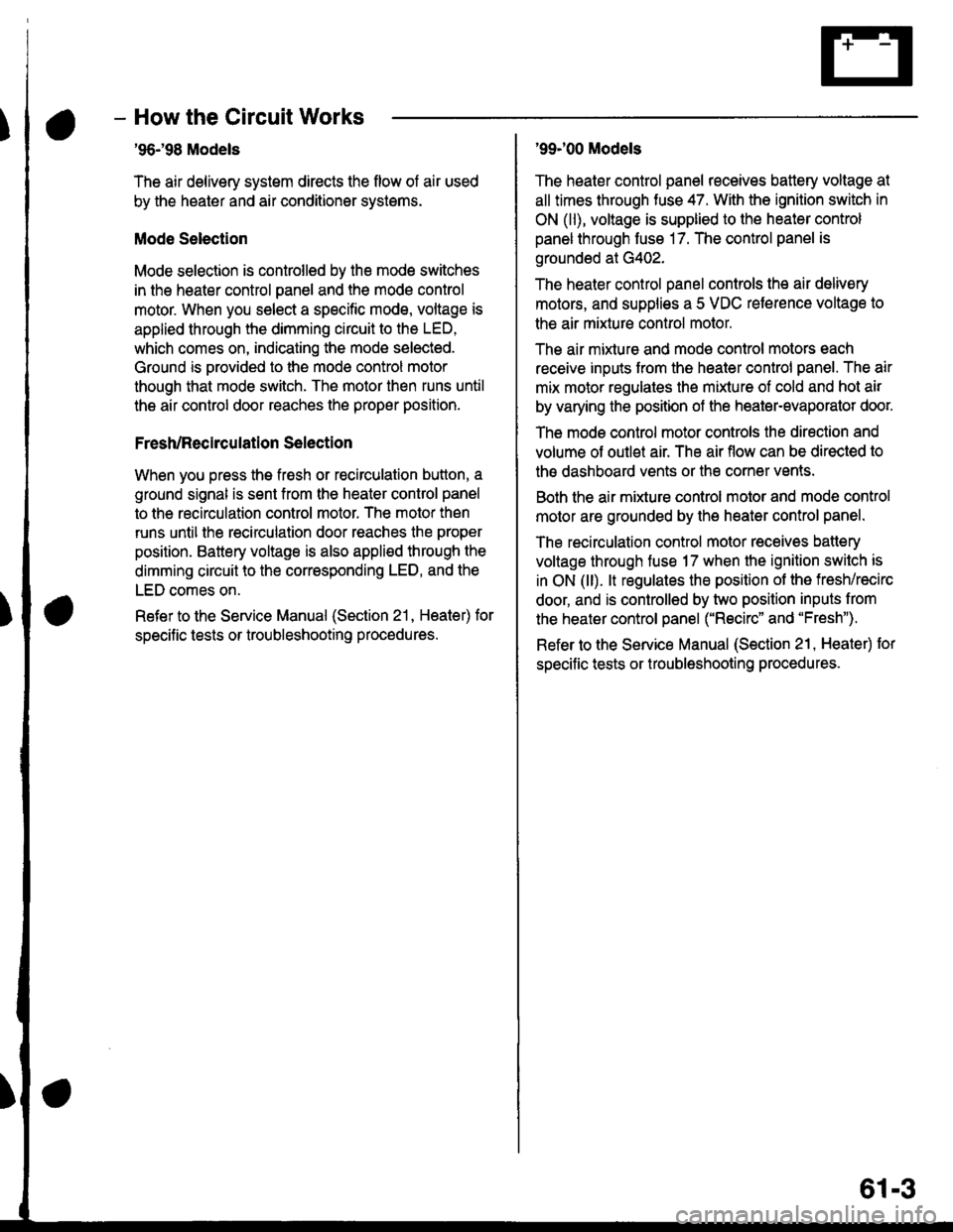
- How the Circuit Works
'96198 Models
The air delivery system directs the flow of air used
by the heater and air conditioner systems.
Mode Selection
Mode selection is controlled by the mode switches
in the heater control panel and the mode control
motor. When you select a specific mode, voltage is
applied through the dimming circuit to the LED,
which comes on, indicating the mode selected.
Ground is orovided to the mode control motor
though that mode switch. The motor then runs until
the air control door reaches the proper position.
Fresh/Recirculation 56lection
When you press the fresh or recirculation button, a
ground signal is sent from the heater control panel
to the recirculation control motor. The motor then
runs until the recirculation door reaches the proper
position. Battery voltage is also applied through the
dimming circuit to the corresponding LED, and the
LED comes on.
Refer to the Service Manual (Section 21, Heater) for
specitic tests or troubleshooting proc€dures.
'99J00 Models
The heater control panel receives battery voltage at
all times through fuse 47. With the ignition switch in
ON (ll), voltage is supplied to the heater control
panel through fuse 17. The control panel is
grounded at G402.
The heater control panel controls the air delivery
motors, and supplies a 5 VDC reterence voltage to
the air mixture control motor.
The air mixture and mode control motors each
receive inputs trom the heater control panel. The air
mix motor regulates the mixture of cold and hot air
by varying the position of the heater-evaporator doot
The mode control motor controls the direction and
volume of outlet air. The air flow can be directed to
the dashboard vents or the corner vents.
Both the air mixture control molor and mode control
motor are grounded by the h€aler control panel.
The recirculation control motor receives battery
voltage through fuso 17 when the ignition swilch is
in ON (ll). lt regulates the position of the fresh/recirc
door, and is controlled by two position inputs from
the heater control panel ("Recirc" and "Fresh").
Refer to the Service Manual (Section 21, Heater) tor
specific tests or troubleshooting procedures.
61-3
Page 1957 of 2189

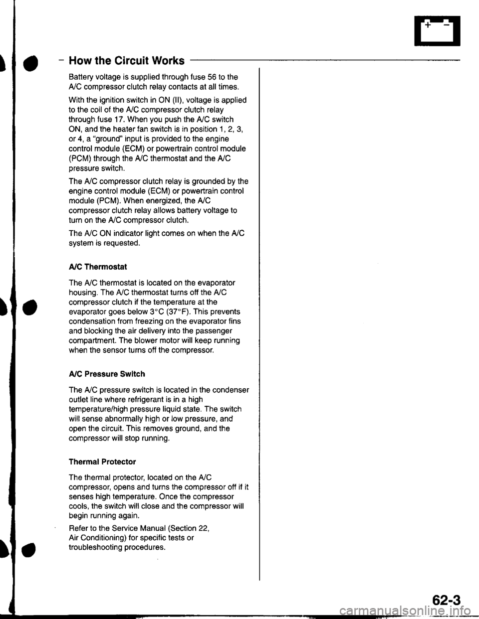
- How the Circuit Works
Battery voltage is supplied through tuse 56 to the
A,/C compressor clutch r€lay contacts at all times.
With the ignition switch in ON (ll), vollage is applied
to the coil of the A,/C compressor clutch relay
through fuse 17. When you push the A,/C switch
ON, and the heater fan switch is in position | , 2, 3,
or 4, a "ground" input is provided to the engine
control module (ECM) or powertrain control module
(PCM) through the l'lC thermostat and the l'lC
pressure switch.
The A,/C compressor clutch relay is grounded by the
engine control module (ECM) or powertrain control
module (PCM). When energized, the A'lC
compressor clutch relay allows battery voltage to
turn on the A,/C comDressor clutch.
The A,/C ON indicator light comes on when the A,/C
system is requested.
A,/C Thermostat
The A'lC thermostat is located on the evaoorator
housing. The A,/C thermostat turns off the A,/C
compressor clutch if the temperature at the
evaporator goes below 3'C (37'F). This prevents
condensation from freezing on the evaporator fins
and blocking the air delivery into the passenger
compartment. The blower motor will keep running
when the sensor turns off the comDressor.
A,/C Pressure Switch
The fuC oressure switch is located in the condenser
outlet line where refrigerant is in a high
temperature/high pressure liquid state. The switch
will sense abnormally high or low pressure, and
open the circuit. This removes ground, and the
compressor will stop running.
Thermal Protectot
The thermal protector, located on the A,/C
compressor, opens and turns the compressor off if it
senses high temperature. Once the compressor
cools, the switch will close and the compressor will
begin running again.
Refer to the Service Manual (Section 22,
Air Conditioning) for specific tests or
troubleshooting procedures.
62-3