2000 HONDA CIVIC Electric
[x] Cancel search: ElectricPage 963 of 2189
Electrical Troubleshootang ('gg - 00 Models)
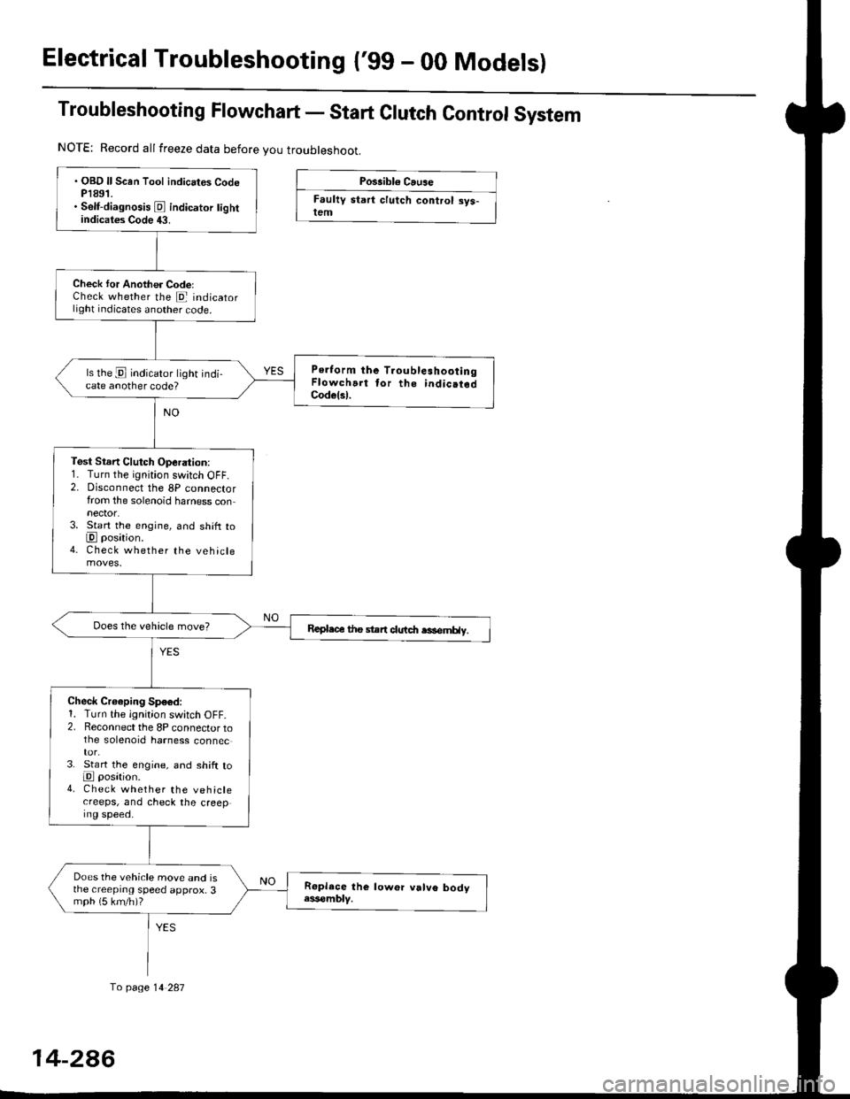
Troubleshooting Flowchart - Start Clutch Control System
Possibl€ Cause
Faultv start clutch control sys-lem
NOTE: Record allfreeze data before you troubleshoot.
fo page 14 287
. OBD ll Scan Tool indicates CodeP1891.. Self-diagnosis E indicator tightindicates Code 43.
Check for Another CodelCheck whether the E indicatorlight indicates another code.
Perform the TroubleshootingFlowchart tor the indic.tedCodelsl.
ls the E indicator light indi-cate another code?
Test Stsn Clutch Operation:1. Turn the ignition switch OFF.2. Disconnect the 8P connectorfrom the solenoid harness connector.3. Start the engine, and shift toE position.4. Check whether the vehiclemoves.
Repl.c€ the stan clutdt rasemHy.
Check Croeping Sp€6d:1. Turn the ignition switch OFF.2. Reconnect the 8P connector tothe solenoid harness connec
3. St€rt the engine, and shift toE posation.4. Check whether the vehiclecreeps, and check the creeping speed.
Does the vehicle move and isthe creeprng speed approx, 3mph (5 km/h)?
14-2A6
Page 965 of 2189
Electrical Troubleshooting ('99 - 00 Models)
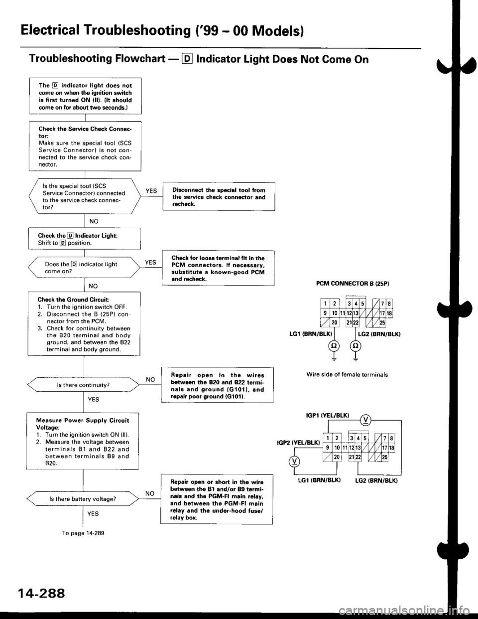
Troubleshooting Flowchart - El Indicator Light Does Not Come On
PCM CONNECTOR B I25PI
LGl {BRN/BLK)
Wire side ot female terminals
LGlIARN/BLK) LG2IBRN/BLKI
The D indicator light does notcome on whon ths ignhion switchis tirst turned ON {lll. llt shouldcome on tor about two s€conds.)
Check the Service Check Connec-tor:Make sure the special tool {SCSService Connectorl is not connected to the service check con-nector,
ls the special tool (SCS
Service Connectorl connectedto the service check connec-tor?
Disconnect the sp€cial tool f]omthe seruice chcck connoclor andaecheck.
Check the E Indicalor Light:Shift to E posjtion.
Check tor loose te.minal fit in thePCM connectors, lf nocessary,substitute a known-good PCMand aecheck.
Does the E indicator light
Check the Ground Circuit:1. Turn the ignition switch OFF.2. Disconnect the B (25P) connector from the PCM.3. Check tor continuity betweenthe 820 terminal and bodyground, and between the 822terminal and body ground.
Fepair open in th. wirosb€tw.en the 820 end 822 termi-nals and ground {G1011, !ndrepair poor ground {G1011.
ls there continuity?
Measure Power Supply CircuitVoltage:1. Turn the ignitlon switch ON (ll).
2. Measure the voltage betweenterminals Bl and 822 andbetween terminals B9 and820.
Ropair op€n or short in tho wireb€tween the Bl and/or B!| tarmi-nds and the PGM-FI main .ohy,and between tho PGM-FI mainrelay and the under-hood fuso/r€lav box.
ls there battery voltage?
To page 14-289
14-2AA
Page 967 of 2189
ElectricalTroubleshooting ('gg - 00 Models)
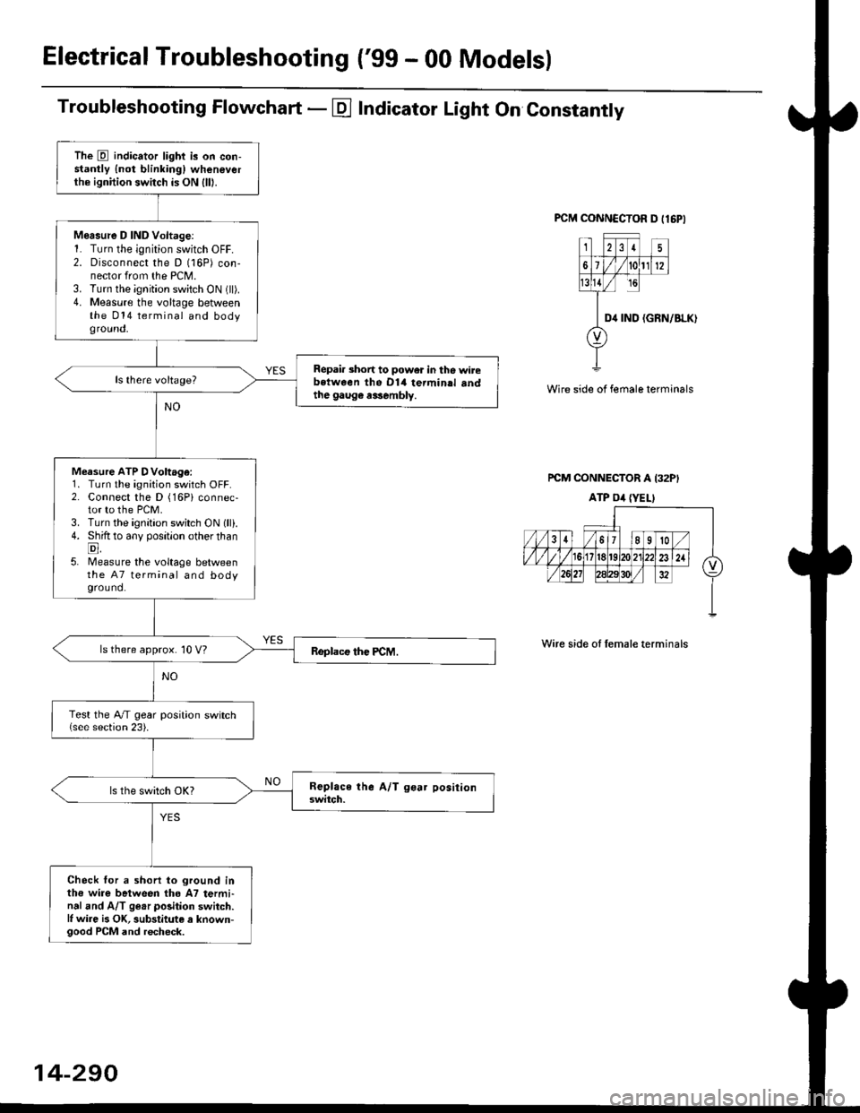
Troubleshooting Flowchart - E Indicator Light On Constantly
FCM CONNCCTOR D tl6PI
23I5
61t012
tsll / rc
II D4 rND
o
(GRN/BLK)
Wire side of female terminals
rcM CONNECTOR A I32PI
ATP Dil {YELI
Wire side of lemale terminals
The E indicator light is on con-stantly {not blinkingl wheneverthe ignition switch is ON lll|.
Mersure D IND Voltage:1. Turn the ignition switch OFF.2. Disconnect the D (16P) con-nector from the PCM.3. Turn the ignition switch ON (ll).4. Measure the voltage betweenthe 014 terminal and bodyground,
Repair short to power in tho wirebstween the Dl4 termin.l sndthe gaug€ r3sembly.
Measure ATP DVoltage:1. Turn the ignition switch OFF.2. Connect the D (16Pi connec-tor to the PCM.3. Turn the ignition switch ON lll).4. Shift to any position other thanE,5. lMeasure the voltage betweenthe 47 terminal and bodyground.
ls there approx. 10 V?
Test the A/T gear position switch{see section 23).
Check for a shorl lo ground inthe wire between tho A7 termi-nal and A/T ge.r polition switch.l, wire is OK, substitute a known-good PCM and recheck.
14-290
Page 970 of 2189
Start Clutch Control@
T
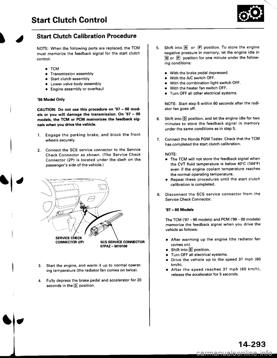
Start Clutch Calibration Procedure
NOTE: When the following parts are replaced, the TCM
must memorize the feedback signal for the start clutch
control.
. TCM
. Transmissionassembly
. Stan clutch assembly
. Lower valve bodv assembly
. Engine assembly or overhaul
'96 Model Only
CAUTION: Do not uso this procsdure on'97 - (X) mod-
els or you will damage the transmission. On '97 - 00
models, the TCM or PCM memorizes ths loodback sig'
nals when you drive the vehicle.
1. Engage the parking brake, and block the front
wheels securely.
2. Connect the SCS service connector to the Service
Check Connector as shown. (The Service Check
connector (2P) is located under the dash on the
passenger's side of the vehicle.)
CONNECTOR07PAZ - lDl01(xt
Start the engine, and warm it up to normal operat-
ing temperature (the radiator fan comes on twice).
Fully depress the brake pedal and accelerator for 20
seconds in the E] position.
rl ,
CONNECTOR I2PI
14-293
7.
Shift into E o|. E position. To store the engine
negative pressure in memory. Iet the engine idle in
E or E position for one minute under the follow-
ing conditions:
. With the brake pedal depressed,
. with the y'\/c switch oFF.
. With the combination light switch OFF.
. With the heater fan switch OFF.
. Turn OFF all other electrical systems
NOTE: Start step 5 within 60 seconds after the radi-
ator fan goes off.
Shift into E position, and let the engine idle for two
minutes to store the feedback signal in memory
under the same conditions as in step 5.
Connect the Honda PGM Tester. Check that the TCM
has completed the start clutch calibration.
NOTE:
. The TCM will not store the feedback signal when
the CVT fluid temperature is below 40"C (104'F)
even if the engine coolant temperature reaches
the normal operating temperature.
. Repeat these procedures until the start clutch
calibration is completed-
Disconnect the SCS service connector from the
Service Check Connector.
'97 - 00 Models
The TCM ('97 - 98 models) and PCM ('99 - 00 models)
memorize the feedback signal when you drive the
vehicle as follows:
. After warming up the engine (the radiator fan
comes onl.
. Shift into E position.
. Turn OFF all electrical systems,
. Drive the vehicle up to the speed 37 mph (60
km/h).
. After the speed reaches 37 mph (60 km/h),
release the accelerator for 5 seconds.
Page 1374 of 2189
Heater and Air Conditioning
Heater '.'..""" 21'1
Air Conditioning ......."'.. "' 22-1
SUPPLEMENTAL RESTRAINT SYSTEM (SRS}
The civic sRs includes a driver's airbag located in the steering wheel hub ln addition, all models (except some
models for canada) have a passenger's airbag located in the dashboard above the glove box'
Information necessary to safely service the sRS is included in this service Manual ltems marked with an asterisk (*)
on the contents page include, or are located near, sRs components. servicing, disassembling or replacing these
items will require special precautions and tools, and should therefore be done by an authorized Honda dealer'
@-";;il rendsring the SRS inoperative, which could lead to personal iniury or deaih in the svent of a sev€re
frontal collision. all SRS service work must be pertormed by an authorized Honda d€aler'
. lmploper service procedures, including incorrest removal and instsllation of the sRs, could lead to personal
iniury caused by unintentional deployment of the airbags'
o Do not bump the SRS unit. Otherwise. the system may fait in case of a collision. or the airbags may deploy
when the ignition switch is ON {ll}'
. sRs electrical wiring harncsses are id€ntified by yellow colol coding. Related components ale located in lhe
steering column, front console, dashboard, dashboald lowet panel, and in the dashboard above the glove box'
Do not use electricaltest equipment on these circuits.
Page 1393 of 2189
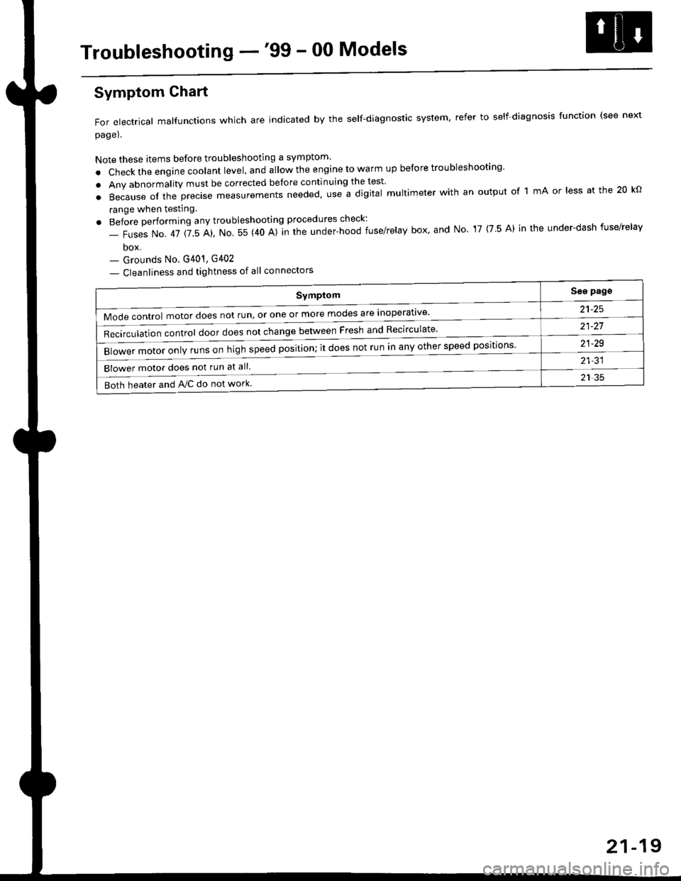
Troubleshooting -'99 - 00 Models
Symptom
Mode control motor does not run, or one or more modes are inoperat've'
Recirculation control door does not change between Fresh and Recirculate'
Blower motor only runs on high speed position; it does not run in any other speed positions
Blower motor does not run at all.
Both heater and Ay'C do not work
See pags
a1_tq
21-21
21-29
21-31
21 35
Symptom Chart
For electrical malfunctions which are indicated by the self-diagnostic system, refer to self-diagnosis function (see next
page).
Note these items before troubleshooting a symptom'
. Check the engine coolant level, and allow the engine to warm up before troubleshooting'
. Any abnormality must be corrected before continuing the test
.Becauseoftheprec|semeasurementsneeded,UseadigitaImu|timeterwithanoutputoflmAor|essatthe20ko
range when testing
. Before performing any troubleshooting procedures check:
- Fuses No. 41 115 Al, No 55 (40 A)]n the under-hood fuse/relay box' and No 17 (7 5 A) in the under-dash fuse/relav
box- Grounds No. G401, G402
- Cleanliness and tightness of all connectors
21-19
Page 1471 of 2189

l'f .
Electrical
Special Toofs .,....................,23-2
Troubleshooting
Tips and Precautions ..............,.................... . 23-3
Five-step Troubleshooting .............. ......... . . 23-5
wire color codes ..........,23-5
Schematic Symbols ........,................... . . .. .... 23-6
Relay and Control Unit Locations
Engine Compartment ...,..................... ... .. . 23'7
Dashboard ......................23-8
Dashboard/Door ......... 23-12*Airbags ................. ....... Section 24
Air Conditioning ......... Section 21
Aftelnator ..........."""" """ 23-112
Anti-lock Brake System {ABS) Section 19*A/T Gear Position Indicator .....................,. .... ... 23-149
Automatic Transmission Svstem .... . ....... Section 14
Batterv ......... . . . ... ...... .......23-91
Blower controls .. . ... Section 2l
Charging System ....'...........23'112
Connector ldentilication and Wire Harness
Routing .................. ......23'13
Cruise Control ............,........23-240
Dash Lights Brightness Controller ............. ....... 23-180
Fan controfs "" 23'126
Fuel PumD ........ . ........ section 11
Fuses/Refay ...............,..,,.. 23'62
PGM-FI Control System ......................,....... Section 1 1
*Gauges
Circuit Diagram ....,.,.......23-131
Fuef Gauge ...........'.'.......23-142
Gauge/lndicator .. . .. 23-129
Ground Distribution .. . 23-75
Heatei controls .. . ..... Section 21*Horn................. ...............23-196
*tgnition Switch ....................23-89
lgnition System .......,.... 23-102
*lntegrated Control Unit ....................................... 23-156
fnterlock System ,........ . . , ,23-144
Lighting System . . . .. ......... 23-161
Lights, Exterior
Back-up Lights ..'............23'171
Brake Lights .................. 23'174
Daytime Bunning Lights (Canadal ............... 23'166
Front Parking Lights ......,................ .'. .......... 23-167
Front Turn Signal Lights .......... . . ............ ..,.23-167
Headtights ....".'....-... ..... 23'167
High Mount Brake Light ...................... ... .23'179
License Plate Lights ...... 23'176
Taitfights ................ .......23'171
lnterior Lights ..-.......,, . 23-142
Moonroof ..,.................,........ 23-235
Power Distribution ....... . . .23-61
Power Door Locks .......,,,. .23'251
Power Mirrors ,..............,.,...23'206
Power Relays ....... . ...... . . .. 23-86
Power Windows ............,,....23-220
Rear Window Defogger .......................... . . ... . . 23-2OO
Spark Plugs . ..... . ........ .....23-111
Slarting System ................23-93*stereo Sound Svstem ,................. ..... ... . ... ,.,.,,23'147'Supplemental Restraint System (SRS) ... . Section 24
Turn Signal/Hazard Flasher System .......'.'....-... 23-173
*Undel-dash Fuse/Relay Box ............,.................. 23-85
vehicfe soeed sensor (VSSI """" ""' 23-140+Wipers/Washers .........,.,.,...23-214
NOTE: Unless otherwise specified, references to auto-
matic transmission (Mf) in this section include the CVT.
Page 1474 of 2189
Troubleshooting
Tips and Precautions (cont'dl
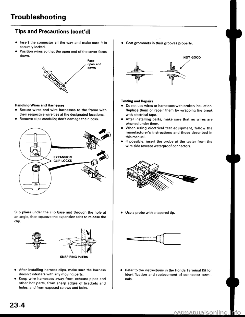
Insert the connector all the way and make sure it is
securelv locked.
Position wires so that the open end of the cover faces
down.
After installing harness clips, make sure the harness
doesn't interfere with any moving pans.
Keep wire harnesses away from exhaust pipes and
other hot parts. from sharp edges of brackets and
holes, and from exDosed screws and bolts.
V
F6c6op€n end
Handling Wires and Harnosscs
. Secure wires and wire harnesses to the frame with
their respective wire ties at the designated locations,
. Remove clips carefully; don't damage their locks.
Slip pliers under the clip base and through the hole at
an angle, then squeeze the expansion tabs to release the
clrp.
SNAP-BING PLIERS
23-4
NOT GOOO
ll il,/
s*' -.1}8."/_Y--_Y5\
il ,,
Testing and Repairs
o Do not use wires or harnesses with broken insulation.
Replace them or repair them by wrspping the break
with electricaltaoe.
. After installing parts, make sure that no wires arepinched under them.. When using electrical test equipment, follow the
manufacturer's instructions and those described in
this manual.
. lf possible, insert the probe of the tester from the
wire side (except waterproof connector).
. Seat grommets in their grooves properly.
. Use a probe with a tapered tip.
Refer to the instructions in the Honda Terminal Kit for
identification and replacement of connector termi-
nats.