Page 193 of 2189
Rocker Arms
lnstallation
1.
2.
3.
lnstall the rocker arms in the reverse order of
removal:
. Valve adjusting locknuts should be loosened and
the adiusting screw, backed off before installa-
tron.
. The component parts must be reinstalled in the
original locations.
lnstall the lost motion assemblies.
lnstall the rocker arms while inserting the rocker
arm shaft into the cylinder head
NOTE: Remove the rubber band after installing the
rocker arms.
12 mm BOLT
\
6-83
4. Clean and install the rocker shaft orifices with new
O-rings. lf the holes in the rocker arm shaft and
cylinder head are not in line with each other, screw
a 12 mm bolt into the rocker arm shaft and rotate
the shaft.
NOTE: The shapes of the rocker shaft orifices tor
the intake and exhaust are different. The orific'
must be installed in the proper locations.
INTAKE ROCKER
SHAFT ORIFICE
EXHAUST ROCKER Clean
SHAFT ORIFICE
O.RING
O
Page 196 of 2189

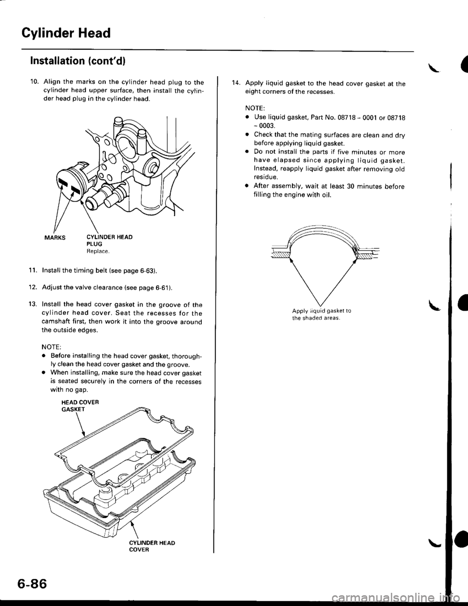
Cylinder Head
Installation (cont'dl
10. Align the marks on the cylinder head plug to thecylinder head upper surface, then install the cylin,
der head plug in the cylinder head.
PLUGReplace.
Install the timing belt (see page 6-63).
Adjust the valve clearance (see page 6-61).
Install the head cover gasket in the groove of the
cylinder head cover. Seat the recesses for the
camshaft first, then work it into the groove around
the outside edges,
NOTE:
. Before installing the head cover gasket, thorough-ly clean the head cover gasket and the groove.
. When installing, make sure the head cover gasket
is seated securely in the corners of the recesses
wrrn no gap.
11.
13.
1'
CYLINDEB HEAD
HEAD COVEB
6-86
(\
14. Apply liquid gasket to the head cover gasket at theeight corners of the recesses.
NOTE:
. Use liquid gasket, Part No. 08718 - 0001 or 08718- 0003.
. Check that the mating surfaces are clean and drybefore applying liquid gasket
. Do not install the parts if five minutes or morehave elapsed since applying tiquid gasket.
Instead, reapply liquid gasket after removing oldrestdue.
. After assembly. wait at least 30 minutes before
filling the engine with oil.
Page 237 of 2189
Oil Pump
Overhaul
NOTE:
. Use new O rings when reassembllng.
. Apply oil to O-rings before installation.
. Use liquid gasket, Part No. 08718 - 0001 or 08718 - 0003
. The rotors must be installed to the same direction in order'
o After reassembly, check that the rolors move without binding'
B15A2 engine:
6x1.0mm7 N.m (0.7 kgf m, 5 lbf ft)
OUTER ROTORInspection, page 8-13
INNER ROTORpage 8-13
OOWELPIN
O-RINGReplace.
6x1.0mm11 N.m (1.1
8 tbtfrlkgf.m,
PUMP HOUSINGInspection, page 8-13
Apply liquid gasket
to the mating surface of
the cylinder blockwhen installing.
8 x 1.25 mm24 N,m {2.i1 kgl.m.
17 tbf.ft)RELIEF VALVEValve mlst slide freeiy
in housing bore.Replace if scored.OIL SEALReplace.lnstallation,page 8-14
SEALING BOLT39 N.m l4O kgt'm,29 tbt frl
\(cont'd)
SPRING
8-11
Page 238 of 2189
Oil Pump
Overhaul (cont'dl
NOIE:
. Use new O rings when reassembling.. Apply oil to O rings before instalraUon.. Use liquid gasket, Parr No. 08718 - 0001 or08718_0003.. The rotors must be installed to the same direction.. After reassembly, check that the rotors move without binding.
D16Y5, D16Y7, D16Y8 engines:
(
6x1.0mm7 N.m (0.7 kgI.m, 5 lbf ftl
PUMP HOUSINGInspection, page 8 13Apply liquid gasketto mating surface ofthe cylinder biockwhen installing.
INNER ROTORInspectron, page 8 13
DOWEL PIN
PUMP COVEB
O-RING
_.feor,""
\6x1.0mm11 N.m {1.1 kgf.m,8lbl.ft)RELIEF VALVEValve must slide freelyin housing bore.Replace if scored
OIL SEAL
[".?li;:;"". *,", ,.rg
""rc
@.-*or"."
9''ggttt*
8-12
Page 244 of 2189
D16Y5 engine:
6x1.0mm12 N'm (1.2 kgl.m,8.? lbf'ft)
EGR CHAMBER
INIAKE MANIFOLDReplace if cracked orif mating surfaces are8 x 1.25 mm21 N m (2.1 kgf.m,15 tbtft)damageo,
INTAKE AIB CONTROL(IAC) VALVE (M/TI
8 x'1,25 mm22 N.m (2.2 kst m, 16lblftl
8 r 1.25 mm2a N.m (2.4 kgt m,17 rbt.ft)
EXHAUST GASRECIRCULATION(EGRIVALVE
8 x 1,25 mm22 N.n 12.2 kol'm,16 tbftr)
INTAKE MANIFOLDBRACKET
8 x 1.25 mm23 N.m 12.3 kgf'm,17 tbt fr)
(cont'd)I
9-3
Page 246 of 2189
816A2 engine:
INTAKE MANIFOLDReplace if cracked orif mating surfaces areoamageo,
8 x 1.25 mm22 N.rA 12.2 kgl.trr,16 tbtftt
o
t_-lUH
E
INTAKE AIR CONTROLIIACI VALVE
8 x 1.25 mm24 N.m 12.4 kgf.m,17 tbtftl
8 x 1.25 mm23 N.m {2.3 kg{.m,17 tbt.ftl
Al N-m 12.2 kgt.m,16 tbt.ftlMANIFOLDBRACKET
n ""\--
VlCd>-^
M\G
yo
9-5
Page 258 of 2189
lv
Engine Hose Connections:
D15Y7 engine:
CONNECTINGPIPE
HEATERHOSES
{cont'd)
IAC VALVE
WATEF BYPASS
THERMOSTATHOUSING
VALVE
10-3
Page 259 of 2189
lllustrated Index
(cont'd)
Engine Hose Connections:
D16Y5, D16Y8 engines:
Replace.
IAC VALVE(M/TI
IAC VALVE{A/T)
WATER BYPASSHOSE
THERMOSTATHOUSING
O.RINGReplace.
\
\
\
\h
CONNECTINGPIPE
HEATERVALVE
HEATERHOS€S
10-4