Page 1575 of 2189

-lgnition Timing Inspection and Setting
1.Check the idle speed, and adjust it it necessary (see
section 'l '1 ).
Pull out the service check connector 2P (BRN and BLK
wires) from the connector holder located under the
dash on the front passenger side, then connect the
SCS service connector (T/N 07PAZ - 0010'100) to it.
Start the engine. Hold the engine at 3.000 rpm with
no load {A,/T in E or E. M/T in neutral) until the
radiator fan comes on, then let it idle.
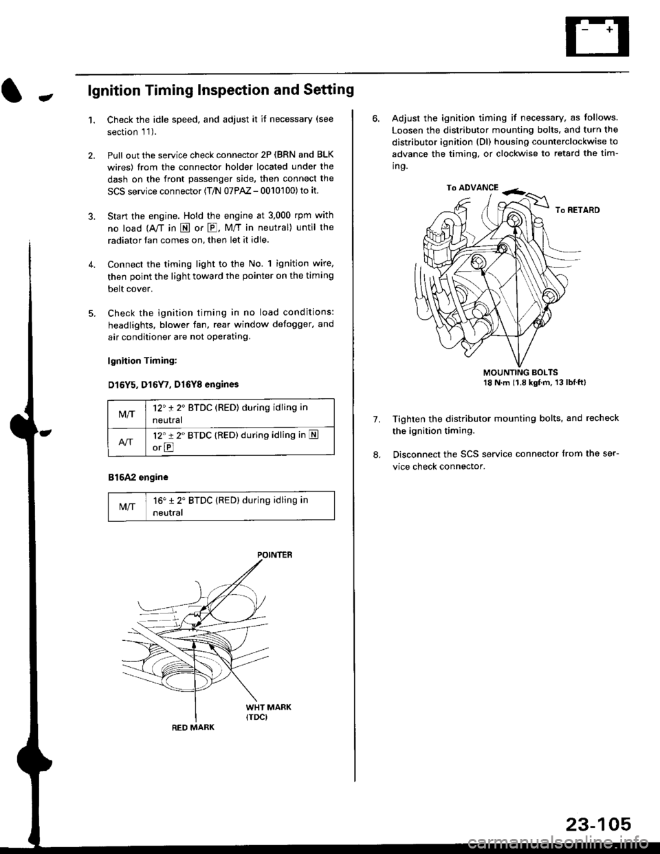
Connect the timing light to the No. 1 ignition wire,
then point the light toward the pointer on the timing
belt cover.
Check the ignition timing in no load conditions:
headlights. blower fan, rear window defogger, and
air conditioner are not operating.
lgnhion Timing:
D15Y5. D16Y7, Dl6Yg engines
816A2 engine
MIT16" 12' BTDC (RED) during idling in
neutral
M/T12't 2" BTDC (RED) during idling in
neutral
l2'r 2" BTDC {RED) during idling in S
orE
POINTEB
RED MARK
23-105
ro ADVANCE -<;,
6. Adjust the ignition timing if necessary, as follows.
Loosen the distributor mounting bolts. and turn the
distributor ignition (Dl) housing counterclockwise to
advance the timing, or clockwise to retard the tim-
ing.
MOUNTING BOLTS18 N'm (1.8 kgfm, 13lblftl
Tighten the distributor mounting bolts, and recheck
the ignition timing.
Disconnect the SCS service connector from the ser-
vice check connector.
7.
Page 1658 of 2189
Stereo Sound System
Component Location Index {cont'd)
SRS components are located ln this area. Review the SRS component locations, precautions, and orocedures in the sRSsection (24) before perlorming repairs or service.
'99 - 00 models
AUDIO UNITFeplacement, page 23-189Terminals, page 23-190
ANTENNA MAST (Coupe/Hatchbeck)Replacement, page 23,193RIGHT TWEETERReplacement, p6ge 23-191
LEFT TWEETERReplacement, page 23-191
ANTENNA LEAD
LEFT FRONTReplacement, page 23-191
RIGHT FRONT SPEAKERReplacernent, page 23-191
WINDOW ANTENNA {SedanlWire Test, page 23 192Wire Repair, page 23-192
SUB
I.TAO
REAR SPEAKERSReplacemont, page 23-191
23-1AA
Page 1664 of 2189
Stereo Sound System
Window Antenna Wire Test
1. Wrap aluminum foil around the tip of the tester
probe as shown.
Touch one tester orobe to the window antenna ter-
minal near, and move the other tester probe along
the antenna wires to check that continuity exists.
WINDOW ANTENNA
23-194
OPEN
Window Antenna Wire Repair
NOTE: To make an effective repair, the broken section
must be no longer than one inch.
1. Lightly rub the area around the broken section with
fine steel wool, then clean it with alcohol.
2. Carefully mask above and below the broken portion
of the window antenna wire with cellophane tape.
CELLOPHANETAPE
Using a small brush, apply a heavy coat of silver
conductive paint extending about 1/8" on both
sides of the break, Allow 30 minutes to dry.
NOTE| Thoroughly mix the paint betore use.
Check for continuity in the repaired wire.
Apply a second coat of paint in the same way. Let it
dry three hours before removing the tape.
Page 1665 of 2189
Window Antenna Coil Test
2.
1.
wtNoowANTENNAcotL
Remove the rear shelf (see section 20).
Disconnect the 2P and lP connectors from the win-
dow antenna coil.
1P CONNECTOB
2P
-l
CONNECTOR
3.Check for continuity between terminal A1 and body
ground and between terminals 41 and 81.
lf there is no continuity at either check, replace the
window antenna coil.
lq 81 1l
tf--llLB2lllL-,--rl
23-195
Mast Antenna Replacement
1.
2.
Disconnect the connector between the antenna lead
and sub antenna lead.
Remove the two mounting screws, then remove the
mast antenna.
MAST ANTENNA
MOUNTING SCREWS
Page 1670 of 2189
Rear Window Defogger
Gomponent Location Index
36 - 98 modols:
UNDER.DASH FUSE/RELAY BOX
REAR WINDOW DEFOGGER SWITCHInput Test, page 23-203
REAR WINOOW DEFOGGERRELAYTest, page 23-86
REAR WINOOW OEFOGGERFunction Test, page 23'202Defogger Wire Repair. page 23 202
23-200
Page 1671 of 2189
'99 - 00 models:
UNDER.OASH FUSE/RELAY BOX
REAR WINDOW DEFOGGER(Built into climate control unit)
REAR WINDOW DEFOGGER
Test, page 23-86
ANTENNA COIL (Sedsn)
f l_ f= L'
''rofia trF.-lj
l-
REAR WINDOW DEFOGGER
I est, page lr- lv.t
23-201
Page 1672 of 2189
Rear Window Defogger
Circuit Diagram
36 - 98 models:IGNITIONswtTcH
/ BAT \+ ots't
\:7 |
I
IIYE
WHT/BLK +WHT
wtNDow
BLKBLU
It-lt-l
TBLK
UNOEF,HOOD FUSE/RELAY BOX
N0.41 (e,oA) No a2 (aoA)
G40lG402G601 : Coupe/SedanG77t :Nalchback
23-202
Page 1673 of 2189
'99 - 00 models
IGNITONSWTCH
-fO Ctsr
\j7 |
I
I
WHT/BLK +WHT
HEATERPUSHswtTcH
BLK
G40lG402
BLK
G401G402
UNDER HOOD FUSEi RELAY BOX
No 4r (80A) No 42 (40A)
8
CLIMATE CONTROLUNIT/ R€ar window delogg€t \I I mer orcLril blill nlo J\climale conlro unil /
I{/\A-4<-INDICATOS(LE0)
II
REAF WINDOWDEFOGGEBswtTcH7 16
,ll
23-203
l-