2000 FORD WINDSTAR spare tire
[x] Cancel search: spare tirePage 116 of 280

Procedure to program spare SecuriLockYkeys to your vehicle
New coded keys must have the correct mechanical key cut for your
vehicle.
Conventional (non-coded) keyscannotbe programmed to your vehicle.
You will need to have two previously programmed coded keys and the
new unprogrammed SecuriLockykey readily accessible for timely
implementation of each step in the procedure. Please read and
understand the entire procedure before you begin.
1. Insert the first previously programmed coded key into the ignition and
turn the ignition from OFF to ON (maintain ignition in ON for at least
one second).
2. Turn ignition to OFF and remove the first coded key from the ignition.
3. Within five seconds of turning the ignition to OFF, insert the second
previously programmed coded key into the ignition and turn the ignition
from OFF to ON (maintain ignition in ON for at least one second but no
more than five seconds).
4. Turn the ignition to OFF and remove the second coded key from the
ignition.
5. Within 10 seconds of turning the ignition to OFF, insert the new
unprogrammed key (new key/valet key) into the ignition and turn the
ignition from OFF to ON (maintain ignition in ON for at least one
second). This step will program your new key to a coded key.
6. To program additional new unprogrammed key(s), repeat this
procedure from step 1.
If the programming procedure was successful, the new coded key(s) will
start the vehicle's engine. The theft indicator (located on the instrument
panel) will light for three seconds and then go out.
If the programming procedure was not successful, the new coded key(s)
will not operate the vehicle's engine. The theft indicator will flash on and
off. Wait at least one minute and then repeat the procedure from step 1.
If failure repeats, bring your vehicle to your dealership to have the new
spare key(s) programmed.
AUXILIARY POWER POINT
The power point is an additional power source for electrical accessories.
An additional power point is located in the rear cargo area.
Controls and features
116
Page 191 of 280
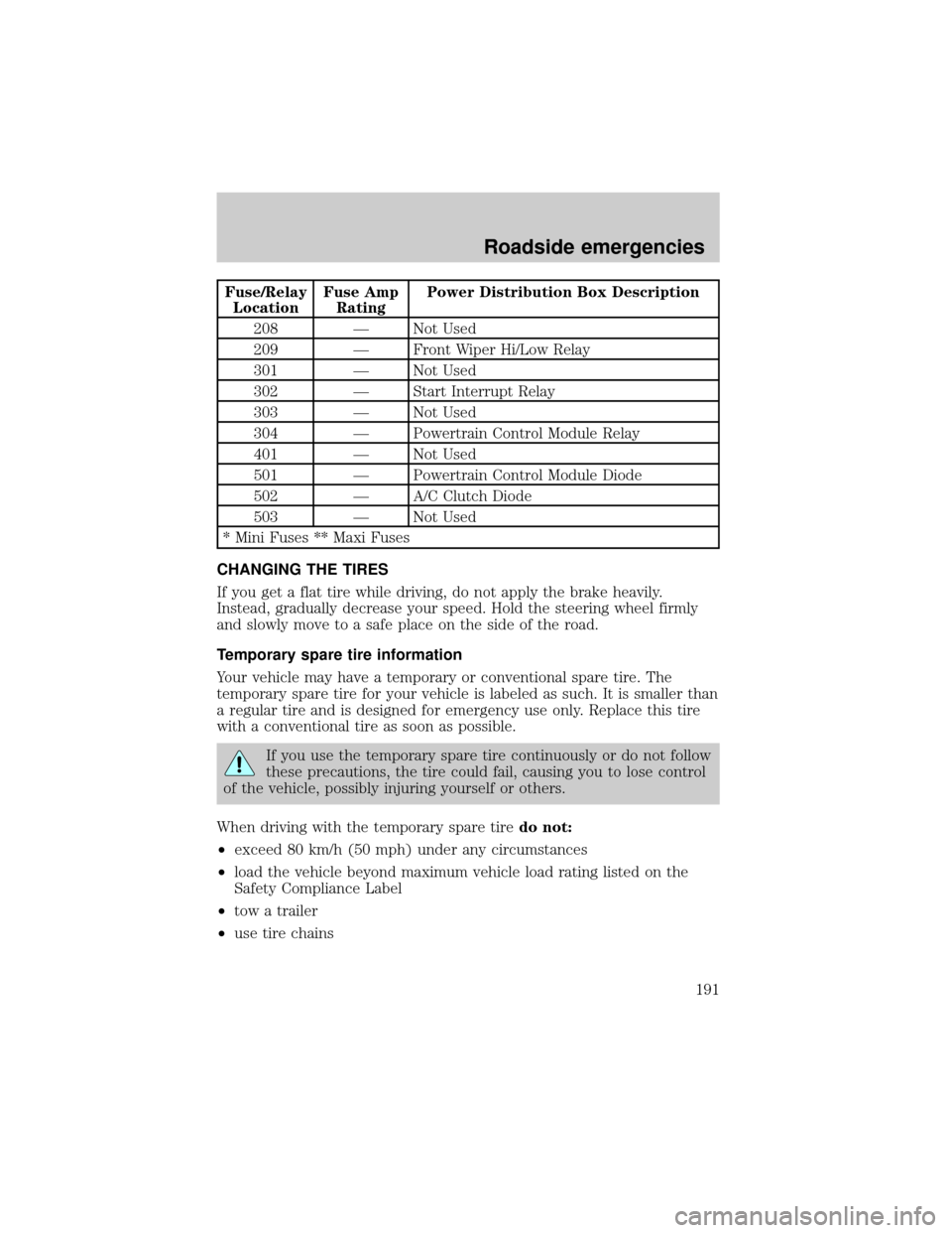
Fuse/Relay
LocationFuse Amp
RatingPower Distribution Box Description
208 Ð Not Used
209 Ð Front Wiper Hi/Low Relay
301 Ð Not Used
302 Ð Start Interrupt Relay
303 Ð Not Used
304 Ð Powertrain Control Module Relay
401 Ð Not Used
501 Ð Powertrain Control Module Diode
502 Ð A/C Clutch Diode
503 Ð Not Used
* Mini Fuses ** Maxi Fuses
CHANGING THE TIRES
If you get a flat tire while driving, do not apply the brake heavily.
Instead, gradually decrease your speed. Hold the steering wheel firmly
and slowly move to a safe place on the side of the road.
Temporary spare tire information
Your vehicle may have a temporary or conventional spare tire. The
temporary spare tire for your vehicle is labeled as such. It is smaller than
a regular tire and is designed for emergency use only. Replace this tire
with a conventional tire as soon as possible.
If you use the temporary spare tire continuously or do not follow
these precautions, the tire could fail, causing you to lose control
of the vehicle, possibly injuring yourself or others.
When driving with the temporary spare tiredo not:
²exceed 80 km/h (50 mph) under any circumstances
²load the vehicle beyond maximum vehicle load rating listed on the
Safety Compliance Label
²tow a trailer
²use tire chains
Roadside emergencies
191
Page 192 of 280
²drive through an automatic car wash, because of the vehicle's reduced
ground clearance
²try to repair the temporary spare tire or remove it from its wheel
²use the wheel for any other type of vehicle
Spare tire information
Your vehicle is equipped with a spare tire thatmust be usedfor
emergencies only. Vehicles equipped with 16º tires have a 15º spare tire.
Vehicles equipped with self-sealing tires do not have a self-sealing spare.
Location of the spare tire and tools
The spare tire and tools for your vehicle are stowed in the following
locations:
Item Location
Spare tire Under the vehicle, just forward of the rear
bumper
Jack, wheel nut
wrench,Behind the access panel located on the right rear
quarter panel interior trim
Jack handle Attached to jack with clip
Removing the jack and tools
1. Locate the access panel on the interior trim. Rotate the two panel
retaining clips and remove the panel.
2. Remove the jack and lug nut wrench by turning the thumbscrew
counterclockwise to remove clamp and relieve tension against the
stowage bracket.
Roadside emergencies
192
Page 193 of 280
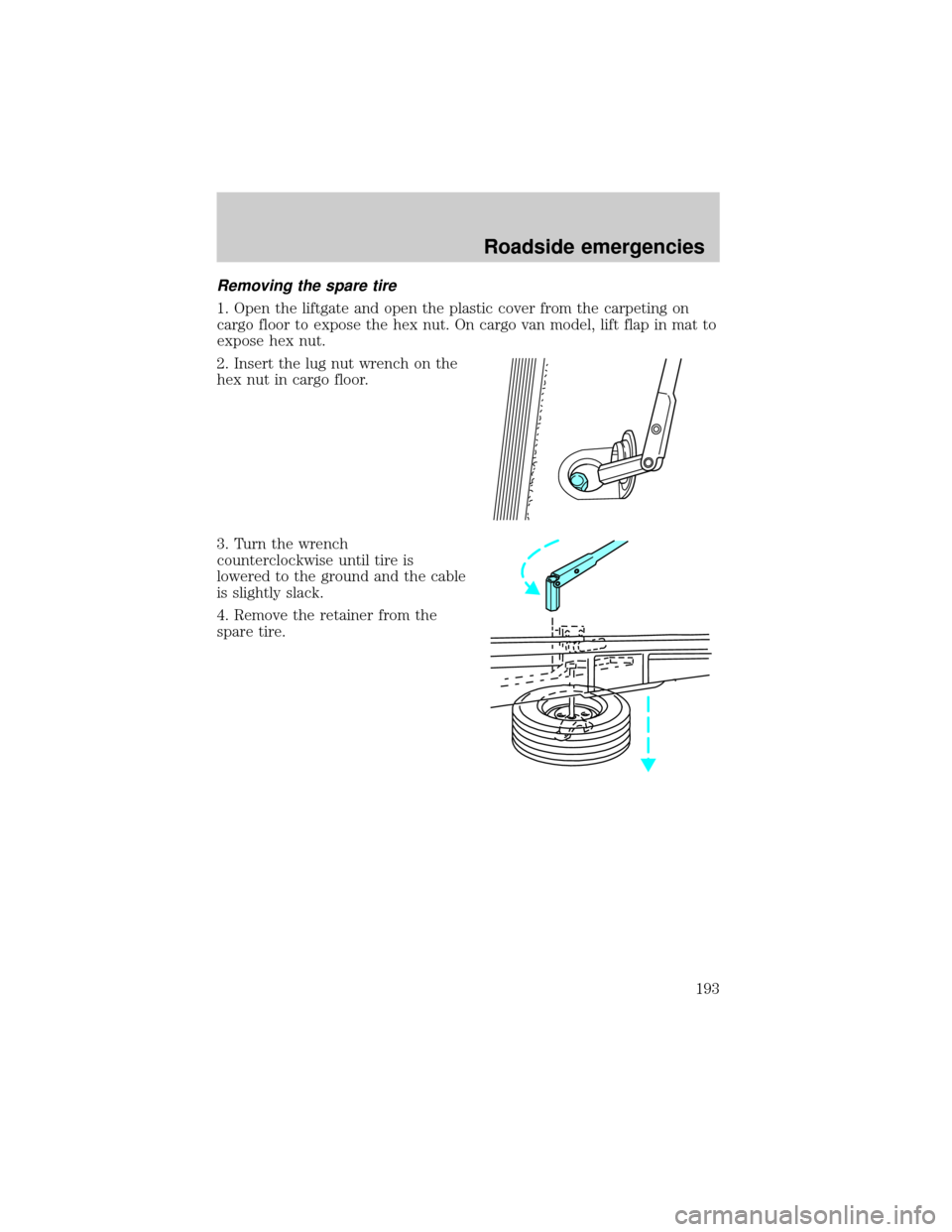
Removing the spare tire
1. Open the liftgate and open the plastic cover from the carpeting on
cargo floor to expose the hex nut. On cargo van model, lift flap in mat to
expose hex nut.
2. Insert the lug nut wrench on the
hex nut in cargo floor.
3. Turn the wrench
counterclockwise until tire is
lowered to the ground and the cable
is slightly slack.
4. Remove the retainer from the
spare tire.
Roadside emergencies
193
Page 194 of 280
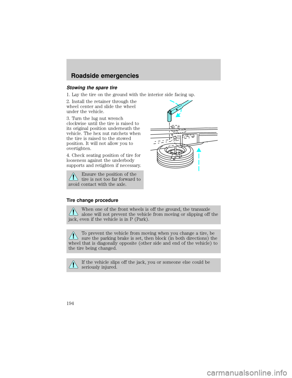
Stowing the spare tire
1. Lay the tire on the ground with the interior side facing up.
2. Install the retainer through the
wheel center and slide the wheel
under the vehicle.
3. Turn the lug nut wrench
clockwise until the tire is raised to
its original position underneath the
vehicle. The hex nut ratchets when
the tire is raised to the stowed
position. It will not allow you to
overtighten.
4. Check seating position of tire for
looseness against the underbody
supports and retighten if necessary.
Ensure the position of the
tire is not too far forward to
avoid contact with the axle.
Tire change procedure
When one of the front wheels is off the ground, the transaxle
alone will not prevent the vehicle from moving or slipping off the
jack, even if the vehicle is in P (Park).
To prevent the vehicle from moving when you change a tire, be
sure the parking brake is set, then block (in both directions) the
wheel that is diagonally opposite (other side and end of the vehicle) to
the tire being changed.
If the vehicle slips off the jack, you or someone else could be
seriously injured.
Roadside emergencies
194
Page 195 of 280
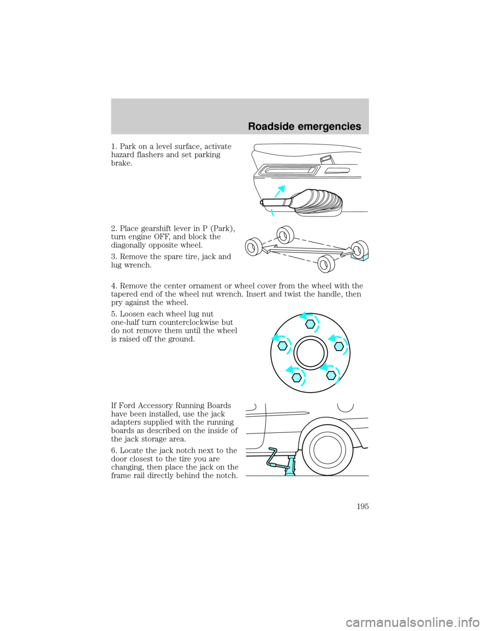
1. Park on a level surface, activate
hazard flashers and set parking
brake.
2. Place gearshift lever in P (Park),
turn engine OFF, and block the
diagonally opposite wheel.
3. Remove the spare tire, jack and
lug wrench.
4. Remove the center ornament or wheel cover from the wheel with the
tapered end of the wheel nut wrench. Insert and twist the handle, then
pry against the wheel.
5. Loosen each wheel lug nut
one-half turn counterclockwise but
do not remove them until the wheel
is raised off the ground.
If Ford Accessory Running Boards
have been installed, use the jack
adapters supplied with the running
boards as described on the inside of
the jack storage area.
6. Locate the jack notch next to the
door closest to the tire you are
changing, then place the jack on the
frame rail directly behind the notch.
Roadside emergencies
195
Page 196 of 280
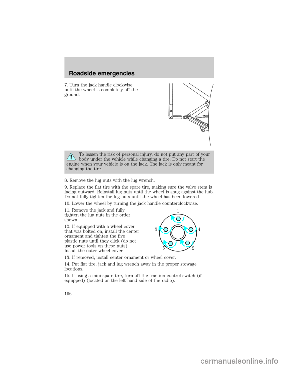
7. Turn the jack handle clockwise
until the wheel is completely off the
ground.
To lessen the risk of personal injury, do not put any part of your
body under the vehicle while changing a tire. Do not start the
engine when your vehicle is on the jack. The jack is only meant for
changing the tire.
8. Remove the lug nuts with the lug wrench.
9. Replace the flat tire with the spare tire, making sure the valve stem is
facing outward. Reinstall lug nuts until the wheel is snug against the hub.
Do not fully tighten the lug nuts until the wheel has been lowered.
10. Lower the wheel by turning the jack handle counterclockwise.
11. Remove the jack and fully
tighten the lug nuts in the order
shown.
12. If equipped with a wheel cover
that was bolted on, install the center
ornament and tighten the five
plastic nuts until they click (do not
use power tools on these nuts).
Install the outer wheel cover.
13. If removed, install center ornament or wheel cover.
14. Put flat tire, jack and lug wrench away in the proper stowage
locations.
15. If using a mini-spare tire, turn off the traction control switch (if
equipped) (located on the left hand side of the radio).
1
4 3
2 5
Roadside emergencies
196
Page 226 of 280
Changing the wiper blades
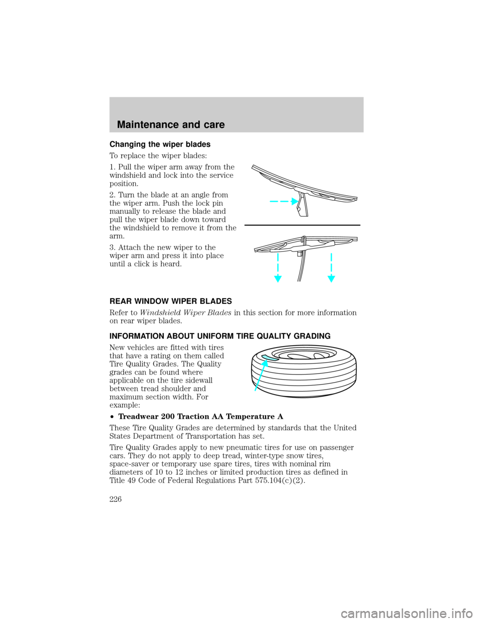
To replace the wiper blades:
1. Pull the wiper arm away from the
windshield and lock into the service
position.
2. Turn the blade at an angle from
the wiper arm. Push the lock pin
manually to release the blade and
pull the wiper blade down toward
the windshield to remove it from the
arm.
3. Attach the new wiper to the
wiper arm and press it into place
until a click is heard.
REAR WINDOW WIPER BLADES
Refer toWindshield Wiper Bladesin this section for more information
on rear wiper blades.
INFORMATION ABOUT UNIFORM TIRE QUALITY GRADING
New vehicles are fitted with tires
that have a rating on them called
Tire Quality Grades. The Quality
grades can be found where
applicable on the tire sidewall
between tread shoulder and
maximum section width. For
example:
²Treadwear 200 Traction AA Temperature A
These Tire Quality Grades are determined by standards that the United
States Department of Transportation has set.
Tire Quality Grades apply to new pneumatic tires for use on passenger
cars. They do not apply to deep tread, winter-type snow tires,
space-saver or temporary use spare tires, tires with nominal rim
diameters of 10 to 12 inches or limited production tires as defined in
Title 49 Code of Federal Regulations Part 575.104(c)(2).
Maintenance and care
226