2000 FORD WINDSTAR warning light
[x] Cancel search: warning lightPage 139 of 280
6. Within seven seconds of the safety belt warning light turning off,
buckle then unbuckle the safety belt.
²This will disable Belt Minder if it is currently enabled, or enable Belt
Minder if it is currently disabled.
7. Confirmation of disabling Belt Minder is provided by flashing the
safety belt warning light four times per second for three seconds.
8. Confirmation of enabling Belt Minder is provided by flashing the safety
belt warning light four times per second for three seconds, followed by
three seconds with the safety belt warning light off, then followed by
flashing the safety belt warning light four times per second for three
seconds again.
9. After receiving confirmation, the deactivation/activation procedure is
complete.
Safety belt maintenance
Inspect the safety belt systems periodically to make sure they work
properly and are not damaged. Inspect the safety belts to make sure
there are no nicks, wears or cuts, replacing if necessary. All safety belt
assemblies, including retractors, buckles, front seat belt buckle
assemblies, buckle support assemblies (slide bar-if equipped), shoulder
belt height adjusters (if equipped), child safety seat tether bracket
assemblies (if equipped), and attaching hardware, should be inspected
after a collision. Ford recommends that all safety belt assemblies used in
vehicles involved in a collision be replaced. However, if the collision was
minor and a qualified technician finds that the belts do not show damage
and continue to operate properly, they do not need to be replaced,
except as described in theReplacing the second row bench seat belt
assemblies after a collisionsection of this chapter. Safety belt
assemblies not in use during a collision should also be inspected and
replaced if either damage or improper operation is noted.
Failure to inspect and if necessary replace the safety belt
assembly under the above conditions could result in severe
personal injuries in the event of a collision.
Refer toCleaning and maintaining the safety beltsin the
Maintenance and caresection.
Seating and safety restraints
139
Page 144 of 280
Several air bag system components get hot after inflation. Do not
touch them after inflation.
If the air bag is deployed,the air bag will not function again
and must be replaced immediately.If the air bag is not
replaced, the unrepaired area will increase the risk of injury in a
collision.
The SRS consists of:
²driver and passenger air bag modules (which include the inflators and
air bags),
²one or more impact and safing sensors,
²a readiness light and tone
²diagnostic module
²and the electrical wiring which connects the components.
The diagnostic module monitors its own internal circuits and the
supplemental air bag electrical system warning (including the impact
sensors), the system wiring, the air bag system readiness light, the air
bag back up power and the air bag ignitors.
Determining if the system is operational
The SRS uses a readiness light in the instrument cluster or a tone to
indicate the condition of the system. Refer to theAir bag readiness
section in theInstrumentationchapter. Routine maintenance of the air
bag is not required.
A difficulty with the system is indicated by one or more of the following:
²The readiness light will either
flash or stay lit.
²The readiness light will not
illuminate immediately after
ignition is turned on.
²A series of five beeps will be heard. The tone pattern will repeat
periodically until the problem and light are repaired.
If any of these things happen, even intermittently, have the SRS serviced at
your dealership or by a qualified technician immediately. Unless serviced,
the system may not function properly in the event of a collision.
Seating and safety restraints
144
Page 146 of 280
How does the side air bag system work?
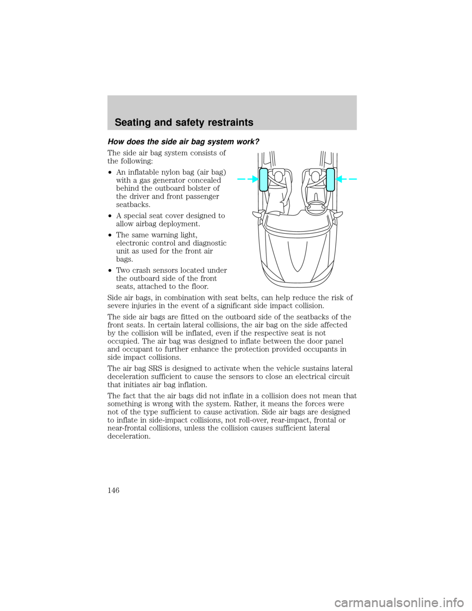
The side air bag system consists of
the following:
²An inflatable nylon bag (air bag)
with a gas generator concealed
behind the outboard bolster of
the driver and front passenger
seatbacks.
²A special seat cover designed to
allow airbag deployment.
²The same warning light,
electronic control and diagnostic
unit as used for the front air
bags.
²Two crash sensors located under
the outboard side of the front
seats, attached to the floor.
Side air bags, in combination with seat belts, can help reduce the risk of
severe injuries in the event of a significant side impact collision.
The side air bags are fitted on the outboard side of the seatbacks of the
front seats. In certain lateral collisions, the air bag on the side affected
by the collision will be inflated, even if the respective seat is not
occupied. The air bag was designed to inflate between the door panel
and occupant to further enhance the protection provided occupants in
side impact collisions.
The air bag SRS is designed to activate when the vehicle sustains lateral
deceleration sufficient to cause the sensors to close an electrical circuit
that initiates air bag inflation.
The fact that the air bags did not inflate in a collision does not mean that
something is wrong with the system. Rather, it means the forces were
not of the type sufficient to cause activation. Side air bags are designed
to inflate in side-impact collisions, not roll-over, rear-impact, frontal or
near-frontal collisions, unless the collision causes sufficient lateral
deceleration.
Seating and safety restraints
146
Page 165 of 280
BRAKES
Your service brakes are self-adjusting. Refer to the scheduled
maintenance guide for scheduled maintenance.
Occasional brake noise is normal and often does not indicate a
performance concern with the vehicle's brake system. In normal
operation, automotive brake systems may emit occasional or intermittent
squeal or groan noises when the brakes are applied. Such noises are
usually heard during the first few brake applications in the morning;
however, they may be heard at any time while braking and can be
aggravated by environmental conditions such as cold, heat, moisture,
road dust, salt or mud. If a ªmetal-to-metal,º ªcontinuous grindingº or
ªcontinuous squealº sound is present while braking, the brake linings
may be worn-out and should be inspected by a qualified service
technician.
Anti-lock brake system (ABS)
On vehicles equipped with an anti-lock braking system (ABS), a noise
from the hydraulic pump motor and pulsation in the pedal may be
observed during ABS braking events. Pedal pulsation coupled with noise
while braking under panic conditions or on loose gravel, bumps, wet or
snowy roads is normal and indicates proper functioning of the vehicle's
anti-lock brake system. The ABS performs a self-check after you start
the engine and begin to drive away. A brief mechanical noise may be
heard during this test. This is normal. If a malfunction is found, the ABS
warning light will come on. If the vehicle has continuous vibration or
shudder in the steering wheel while braking, the vehicle should be
inspected by a qualified service technician.
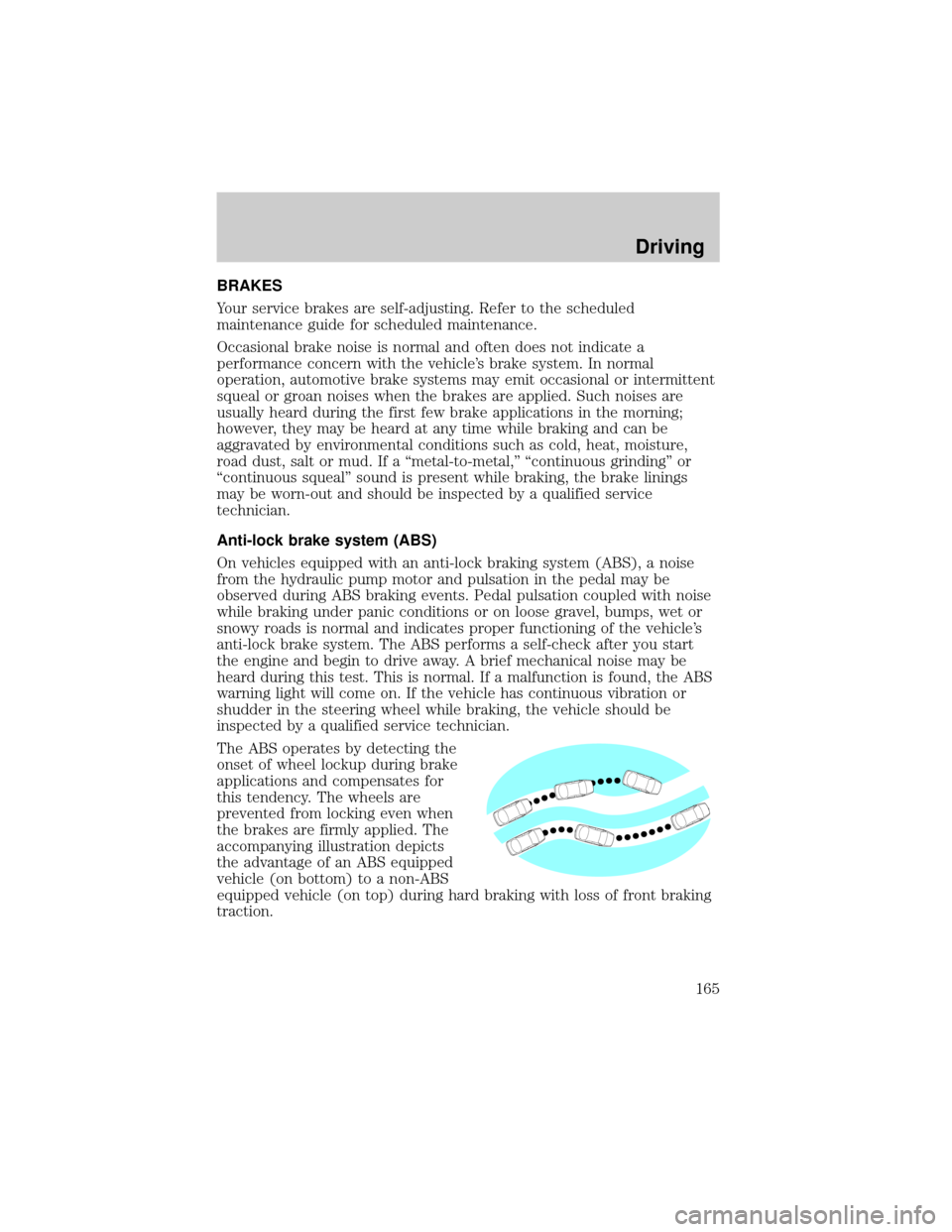
The ABS operates by detecting the
onset of wheel lockup during brake
applications and compensates for
this tendency. The wheels are
prevented from locking even when
the brakes are firmly applied. The
accompanying illustration depicts
the advantage of an ABS equipped
vehicle (on bottom) to a non-ABS
equipped vehicle (on top) during hard braking with loss of front braking
traction.
Driving
165
Page 166 of 280
ABS warning lampABS
TheABSwarning lamp in the instrument cluster momentarily illuminates
when the ignition is turned to the ON position. If the light does not
illuminate momentarily at start up or remains on the ABS needs to be
serviced.
With the ABS light on, the anti-lock
brake system is disabled and normal
braking is still effective unless the
brake warning light also remains
illuminated with parking brake released. (If your brake warning lamp
illuminates, have your vehicle serviced immediately.)
Using ABS
²In an emergency or when maximum efficiency from the ABS is
required, apply continuous force on the brake. The ABS will be
activated immediately, thus allowing you to retain full steering control
of your vehicle and, providing there is sufficient space, will enable you
to avoid obstacles and bring the vehicle to a controlled stop.
²The Anti-Lock system does not decrease the time necessary to apply
the brakes or always reduce stopping distance. Always leave enough
room between your vehicle and the vehicle in front of you to stop.
²We recommend that you familiarize yourself with this braking
technique. However, avoid taking any unnecessary risks.
Parking brake
Apply the parking brake whenever
the vehicle is parked. To set the
parking brake, pull the handle up as
far as possible.
The BRAKE warning lamp in the
instrument cluster illuminates and
remains illuminated (when the
ignition is turned ON) until the
parking brake is released.
!
BRAKE
!
BRAKE
Driving
166
Page 169 of 280
AUTOMATIC TRANSAXLE OPERATION
Brake-shift interlock
This vehicle is equipped with a brake-shift interlock feature that prevents
the gearshift lever from being moved from P (Park) unless the brake
pedal is depressed.
If the gearshift lever cannot be moved from P (Park) with the brake
pedal depressed, it is possible that a fuse has blown or the vehicle's
brakelamps are not operating properly. Refer toFuses and relaysin the
Roadside emergencieschapter.
Do not drive your vehicle until you verify that the brakelamps
are working.
If your vehicle gets stuck in mud or snow it may be rocked out by
shifting from forward and reverse gears, stopping between shifts, in a
steady pattern. Press lightly on the accelerator in each gear.
Do not rock the vehicle if the engine is not at normal operating
temperature or damage to the transaxle may occur.
Do not rock the vehicle for more than a few minutes or damage
to the transaxle and tires may occur or the engine may overheat.
Always set the parking brake fully and make sure the gearshift is
latched in P (Park). Turn off the ignition whenever you leave
your vehicle.
If the parking brake is fully released, but the brake warning lamp
remains illuminated, the brakes may not be working properly.
See your dealer or a qualified service technician.
Driving with an automatic overdrive transaxle with column
gearshift and O/D off switch
Your automatic transaxle electronically controls the shift feel by using an
adaptive learning strategy. This feature is designed to optimize shift
smoothness. It is normal for your transaxle to shift firmly during the first
few hundred kilometers (miles) of operation until the adaptive strategy
has been learned. The adaptive learning strategy is maintained by power
from the battery. When the battery is disconnected or a new battery is
Driving
169
Page 239 of 280
EMISSION CONTROL SYSTEM
Your vehicle is equipped with various emission control components and a
catalytic converter which will enable your vehicle to comply with
applicable exhaust emission standards. To make sure that the catalytic
converter and other emission control components continue to work
properly:
²Use only the specified fuel listed.
²Avoid running out of fuel.
²Do not turn off the ignition while your vehicle is moving, especially at
high speeds.
²Have the items listed in your Scheduled Maintenance Guide performed
according to the specified schedule.
The scheduled maintenance items listed in the Scheduled Maintenance
Guide are essential to the life and performance of your vehicle and to its
emissions system.
If other than Ford, Motorcraft or Ford-authorized parts are used for
maintenance replacements or for service of components affecting
emission control, such non-Ford parts should be equivalent to genuine
Ford Motor Company parts in performance and durability.
Do not park, idle, or drive your vehicle in dry grass or other dry
ground cover. The emission system heats up the engine
compartment and exhaust system, which can start a fire.
Illumination of the ªCheck Engineº light, charging system warning light
or the temperature warning light, fluid leaks, strange odors, smoke or
loss of engine power, could indicate that the emission control system is
not working properly.
Exhaust leaks may result in entry of harmful and potentially
lethal fumes into the passenger compartment.
Do not make any unauthorized changes to your vehicle or engine. By
law, vehicle owners and anyone who manufactures, repairs, services,
sells, leases, trades vehicles, or supervises a fleet of vehicles are not
permitted to intentionally remove an emission control device or prevent
it from working. Information about your vehicle's emission system is on
the Vehicle Emission Control Information Decal located on or near the
Maintenance and care
239
Page 240 of 280

engine. This decal identifies engine displacement and gives some tune up
specifications.
Please consult your ªWarranty Guideº for complete emission warranty
information.
Readiness for Inspection/Maintenance (I/M) testing
In some localities, it may be a legal requirement to pass an I/M test of
the on-board diagnostics system. If your ªCheck Engine/Service Engine
Soonº light is on, refer to the description in theWarning Lights and
Chimessection of theInstrumentationchapter. Your vehicle may not
pass the I/M test with the ªCheck Engine/Service Engine Soonº light on.
If the vehicle's powertrain system or its battery has just been serviced,
the on-board diagnostics system is reset to a ªnot ready for I/M testº
condition. To ready the on-board diagnostics system for I/M testing, a
minimum of 30 minutes of city and highway driving is necessary as
described below:
²First, at least 10 minutes of driving on an expressway or highway.
²Next, at least 20 minutes driving in stop-and-go, city-type traffic with
at least four idle periods.
Allow the vehicle to sit for at least eight hours without starting the
engine. Then, start the engine and complete the above driving cycle. The
engine must warm up to its normal operating temperature. Once started,
do not turn off the engine until the above driving cycle is complete.
BULBS
Replacing exterior bulbs
It is a good idea to check the operation of the following lights frequently:
²Headlamps
²Turn signals
²Cornering lamps
²High-mount brakelamp
²Tail lamps
²Brakelamps
²Backup lamps
²License plate lamps
Maintenance and care
240