Page 7 of 256
Vehicle Symbol Glossary
Child Safety Door
Lock/Unlock
Interior Luggage
Compartment Release
Symbol
Panic AlarmEngine Oil
Engine CoolantEngine Coolant
Temperature
Do Not Open When HotBattery
Avoid Smoking, Flames,
or SparksBattery Acid
Explosive GasFan Warning
Power Steering FluidMaintain Correct Fluid
LevelMAX
MIN
Emission SystemEngine Air Filter
Passenger Compartment
Air FilterJack
Introduction
7
Page 15 of 256

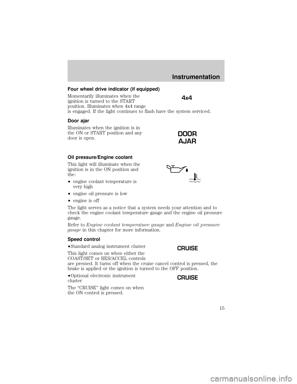
Four wheel drive indicator (if equipped)
Momentarily illuminates when the
ignition is turned to the START
position. Illuminates when 4x4 range
is engaged. If the light continues to flash have the system serviced.
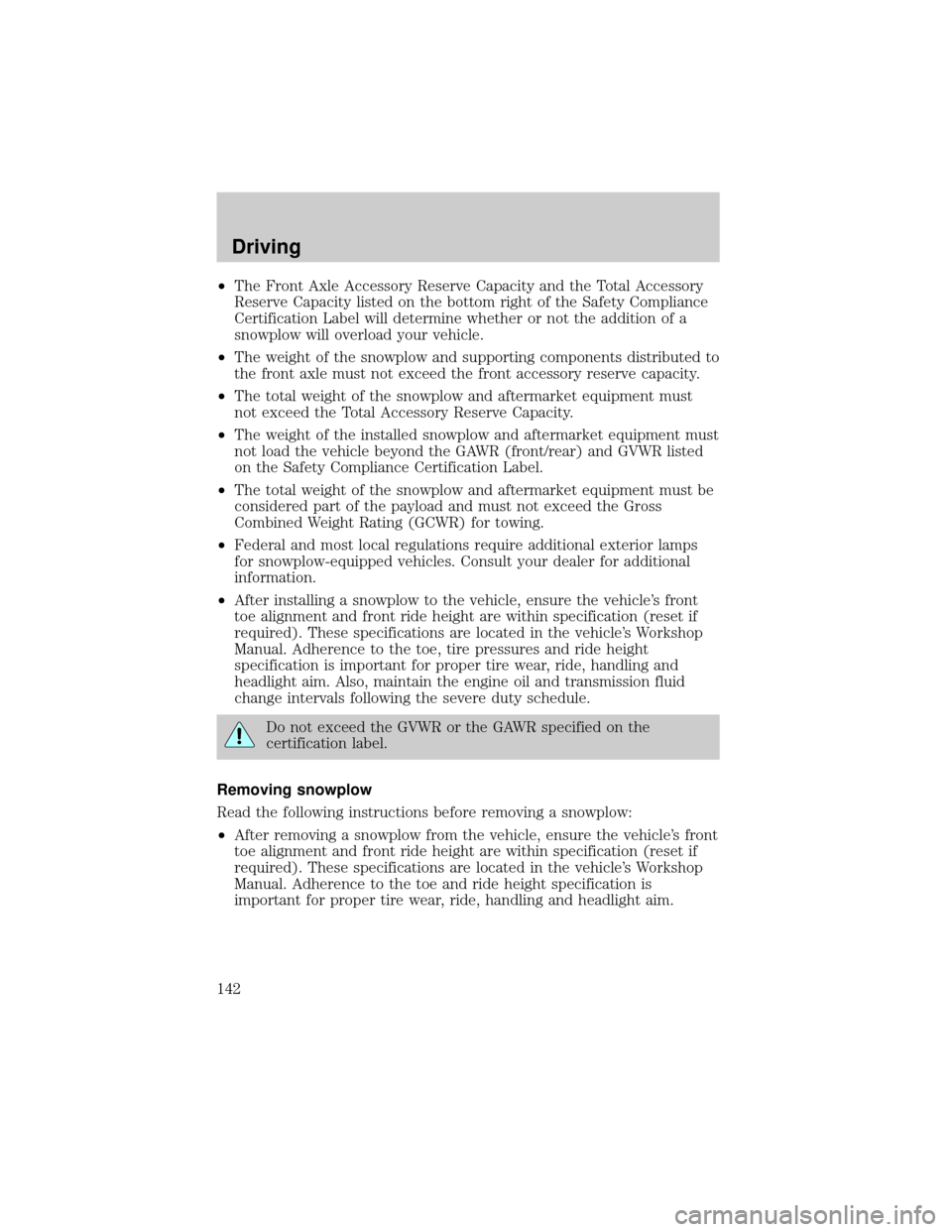
Door ajar
Illuminates when the ignition is in
the ON or START position and any
door is open.
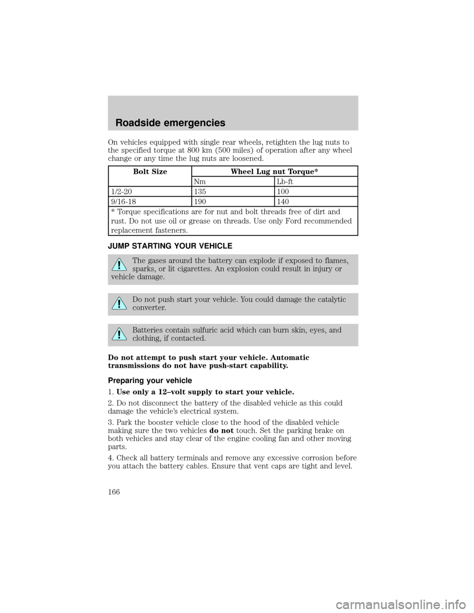
Oil pressure/Engine coolant
This light will illuminate when the
ignition is in the ON position and
the:
²engine coolant temperature is
very high
²engine oil pressure is low
²engine is off
The light serves as a notice that a system needs your attention and to
check the engine coolant temperature gauge and the engine oil pressure
gauge.
Refer toEngine coolant temperature gaugeandEngine oil pressure
gaugein this chapter for more information.
Speed control
²Standard analog instrument cluster
This light comes on when either the
COAST/SET or RES/ACCEL controls
are pressed. It turns off when the cruise cancel control is pressed, the
brake is applied or the ignition is turned to the OFF position.
²Optional electronic instrument
cluster
The ªCRUISEº light comes on when
the ON control is pressed.
4x4
DOOR
AJAR
CRUISE
CRUISE
Instrumentation
15
Page 19 of 256
Tachometer
Indicates the engine speed in
revolutions per minute.
Driving with your tachometer
pointer at the top of the scale or in
the red zone may damage the
engine.
Battery voltage gauge
This shows the battery voltage when
the ignition is in the ON position. If
the pointer moves and stays outside
the normal operating range (as
indicated), have the vehicle's
electrical system checked as soon as
possible.
Engine oil pressure gauge
This shows the engine oil pressure
in the system. Sufficient pressure
exists as long as the needle remains
in the normal range (the area
between the ªLº and ªHº).
If the gauge indicates low pressure,
stop the vehicle as soon as safely
possible and switch off the engine
immediately. Check the oil level.
Add oil if needed (refer toEngine
oilin theMaintenance and care
chapter). If the oil level is correct, have your vehicle checked at your
dealership or by a qualified technician.
RPM1000X0123
5
6 4
818
L
H
Instrumentation
19
Page 142 of 256

²The Front Axle Accessory Reserve Capacity and the Total Accessory
Reserve Capacity listed on the bottom right of the Safety Compliance
Certification Label will determine whether or not the addition of a
snowplow will overload your vehicle.
²The weight of the snowplow and supporting components distributed to
the front axle must not exceed the front accessory reserve capacity.
²The total weight of the snowplow and aftermarket equipment must
not exceed the Total Accessory Reserve Capacity.
²The weight of the installed snowplow and aftermarket equipment must
not load the vehicle beyond the GAWR (front/rear) and GVWR listed
on the Safety Compliance Certification Label.
²The total weight of the snowplow and aftermarket equipment must be
considered part of the payload and must not exceed the Gross
Combined Weight Rating (GCWR) for towing.
²Federal and most local regulations require additional exterior lamps
for snowplow-equipped vehicles. Consult your dealer for additional
information.
²After installing a snowplow to the vehicle, ensure the vehicle's front
toe alignment and front ride height are within specification (reset if
required). These specifications are located in the vehicle's Workshop
Manual. Adherence to the toe, tire pressures and ride height
specification is important for proper tire wear, ride, handling and
headlight aim. Also, maintain the engine oil and transmission fluid
change intervals following the severe duty schedule.
Do not exceed the GVWR or the GAWR specified on the
certification label.
Removing snowplow
Read the following instructions before removing a snowplow:
²After removing a snowplow from the vehicle, ensure the vehicle's front
toe alignment and front ride height are within specification (reset if
required). These specifications are located in the vehicle's Workshop
Manual. Adherence to the toe and ride height specification is
important for proper tire wear, ride, handling and headlight aim.
Driving
142
Page 166 of 256

On vehicles equipped with single rear wheels, retighten the lug nuts to
the specified torque at 800 km (500 miles) of operation after any wheel
change or any time the lug nuts are loosened.
Bolt Size Wheel Lug nut Torque*
Nm Lb-ft
1/2-20 135 100
9/16-18 190 140
* Torque specifications are for nut and bolt threads free of dirt and
rust. Do not use oil or grease on threads. Use only Ford recommended
replacement fasteners.
JUMP STARTING YOUR VEHICLE
The gases around the battery can explode if exposed to flames,
sparks, or lit cigarettes. An explosion could result in injury or
vehicle damage.
Do not push start your vehicle. You could damage the catalytic
converter.
Batteries contain sulfuric acid which can burn skin, eyes, and
clothing, if contacted.
Do not attempt to push start your vehicle. Automatic
transmissions do not have push-start capability.
Preparing your vehicle
1.Use only a 12±volt supply to start your vehicle.
2. Do not disconnect the battery of the disabled vehicle as this could
damage the vehicle's electrical system.
3. Park the booster vehicle close to the hood of the disabled vehicle
making sure the two vehiclesdo nottouch. Set the parking brake on
both vehicles and stay clear of the engine cooling fan and other moving
parts.
4. Check all battery terminals and remove any excessive corrosion before
you attach the battery cables. Ensure that vent caps are tight and level.
Roadside emergencies
166
Page 175 of 256
IDENTIFYING COMPONENTS IN THE ENGINE COMPARTMENT
5.4L V8/6.8L V10 gasoline engines
Refer to the7.3 Liter Power Stroke Direct Injection Turbo Diesel
Owner's Guide Supplementfor diesel engine component locations.
1. Engine oil dipstick
2. Clutch fluid reservoir (manual transmission)
3. Brake fluid reservoir
4. Power distribution box
5. Power steering fluid reservoir
6. Air filter assembly
7. Engine coolant reservoir
8. Windshield washer fluid reservoir
9. Battery
10. Engine oil filler cap
11. Transmission fluid dipstick (automatic transmission)
910111234
867
5
Maintenance and care
175
Page 176 of 256
ENGINE OIL
Checking the engine oil
Refer to the Scheduled Maintenance Guide for the appropriate intervals
for checking the engine oil.
1. Make sure the vehicle is on level ground.
2. Turn the engine off and wait a few minutes for the oil to drain into the
oil pan.
3. Set the parking brake and ensure the gearshift is securely latched in P
(Park) (automatic transmission) or 1 (First) (manual transmission).
4. Open the hood. Protect yourself from engine heat.
5. Locate and carefully remove the
engine oil level indicator (dipstick).
6. Wipe the indicator clean. Insert the indicator fully, then remove it
again.
²If the oil level isbetween the MIN and MAX marks,the oil level is
acceptable.DO NOT ADD OIL.
MIN MAX
Maintenance and care
176
Page 177 of 256

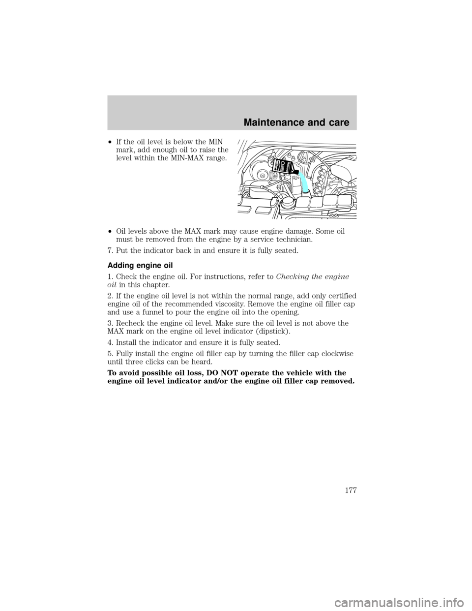
²If the oil level is below the MIN
mark, add enough oil to raise the
level within the MIN-MAX range.
²Oil levels above the MAX mark may cause engine damage. Some oil
must be removed from the engine by a service technician.
7. Put the indicator back in and ensure it is fully seated.
Adding engine oil
1. Check the engine oil. For instructions, refer toChecking the engine
oilin this chapter.
2. If the engine oil level is not within the normal range, add only certified
engine oil of the recommended viscosity. Remove the engine oil filler cap
and use a funnel to pour the engine oil into the opening.
3. Recheck the engine oil level. Make sure the oil level is not above the
MAX mark on the engine oil level indicator (dipstick).
4. Install the indicator and ensure it is fully seated.
5. Fully install the engine oil filler cap by turning the filler cap clockwise
until three clicks can be heard.
To avoid possible oil loss, DO NOT operate the vehicle with the
engine oil level indicator and/or the engine oil filler cap removed.
Maintenance and care
177