Page 142 of 256

•The Front Axle Accessory Reserve Capacity and the Total Accessory
Reserve Capacity listed on the bottom right of the Safety Compliance
Certification Label will determine whether or not the addition of a
snowplow will overload your vehicle.
•The weight of the snowplow and supporting components distributed to
the front axle must not exceed the front accessory reserve capacity.
•The total weight of the snowplow and aftermarket equipment must
not exceed the Total Accessory Reserve Capacity.
•The weight of the installed snowplow and aftermarket equipment must
not load the vehicle beyond the GAWR (front/rear) and GVWR listed
on the Safety Compliance Certification Label.
•The total weight of the snowplow and aftermarket equipment must be
considered part of the payload and must not exceed the Gross
Combined Weight Rating (GCWR) for towing.
•Federal and most local regulations require additional exterior lamps
for snowplow-equipped vehicles. Consult your dealer for additional
information.
•After installing a snowplow to the vehicle, ensure the vehicle’s front
toe alignment and front ride height are within specification (reset if
required). These specifications are located in the vehicle’s Workshop
Manual. Adherence to the toe, tire pressures and ride height
specification is important for proper tire wear, ride, handling and
headlight aim. Also, maintain the engine oil and transmission fluid
change intervals following the severe duty schedule.
Do not exceed the GVWR or the GAWR specified on the
certification label.
Removing snowplow
Read the following instructions before removing a snowplow:
•After removing a snowplow from the vehicle, ensure the vehicle’s front
toe alignment and front ride height are within specification (reset if
required). These specifications are located in the vehicle’s Workshop
Manual. Adherence to the toe and ride height specification is
important for proper tire wear, ride, handling and headlight aim.
Driving
142
ProCarManuals.com
Page 145 of 256

GETTING ROADSIDE ASSISTANCE
To fully assist you should you have a vehicle concern, Ford offers a
complimentary roadside assistance program. This program is separate
from the New Vehicle Limited Warranty. The service is available:
•24–hours, seven days a week
•for the Basic warranty period (Canada) or New Vehicle Limited
Warranty period (U.S.) of three years or 60,000 km (36,000 miles),
whichever comes first on Ford and Mercury vehicles, and four years or
80,000 km (50,000 miles) on Lincoln vehicles
Roadside assistance will cover:
•changing a flat tire
•jump-starts
•lock-out assistance
•fuel delivery
•towing of your disabled vehicle to the nearest Ford dealership, or your
selling dealer if within 25 kms (15.5 miles) of the nearest Ford
Dealership (one tow per disablement). Even non-warranty related
tows, like accidents or getting stuck in the mud or snow, are covered
(some exclusions apply, such as impound towing or repossession).
Using roadside assistance
Complete the roadside assistance identification card and place it in your
wallet for quick reference. In the United States, this card is found in the
Owner Guide portfolio in the glove compartment in Ford vehicles and is
mailed to you if you own a Mercury or Lincoln. In Canada, it is found in
the Roadside Assistance book in the glove compartment.
To receive roadside assistance in the United States for Ford or Mercury
vehicles, call 1-800-241-3673 or if you own a Lincoln vehicle, call
1–800–521–4140. In Canada call 1–800–665–2006.
Should you need to arrange roadside assistance for yourself, Ford will
reimburse a reasonable amount. To obtain information about
reimbursement, call 1-800-241-3673 in the United States for Ford or
Mercury vehicles; or if you own a Lincoln vehicle, call 1–800–521–4140.
Call 1–800–665–2006 in Canada.
Roadside emergencies
145
ProCarManuals.com
Page 150 of 256
The fuses are coded as follows.
Fuse/Relay
LocationFuse Amp
RatingPassenger Compartment
Fuse Panel Description
1 20A Turn/Hazard Lamps
2 10A Airbag Module
3 20A Cigar Lighter, Data Link Connector
4 10A Glove Box Lamp, Map Lamps, Power
Mirrors, Underhood Lamp
5 — Not Used
6 — Not Used
7 5A Power Window/Lock Switch Illumination
8 5A Radio, Headlamp Switch Illumination
9 — Not Used
10 15A Dual Fuel Tanks
11 30A Wiper Motor, Wiper Run/Park Relay Coil,
Wiper Hi/LO Relay Coil, Washer Pump
Relay Coil
12 15A Horn
13 20A Stop Lamps, Center High-mount Stop
Lamp, Trailer Tow Stop Lamp, Speed
Control
14 10A Dome Lamp, Cargo Lamp, Courtesy Lamps,
Running Board Lamps
15 5A Stop Lamp Switch (Logic): Generic
Electronic Module (GEM), Powertrain
Control Module (PCM), Four Wheel
Anti-lock Brake System (4WABS) Module,
Brake Shift Interlock, Cluster and PCM
Keep Alive Memory
16 15A Instrument Cluster, Hi-beam Headlamps
17 — Not Used
18 — Not Used
Roadside emergencies
150
ProCarManuals.com
Page 151 of 256

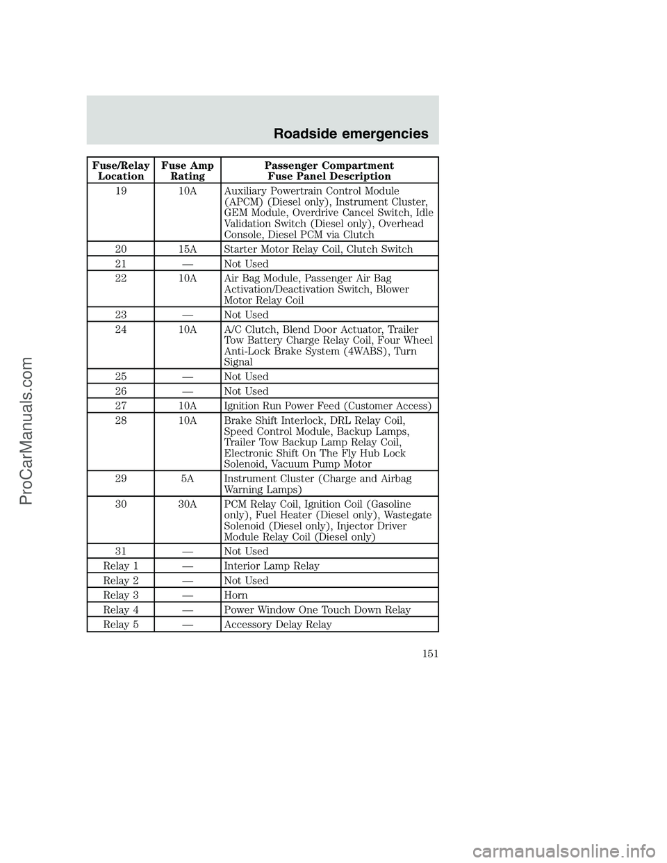
Fuse/Relay
LocationFuse Amp
RatingPassenger Compartment
Fuse Panel Description
19 10A Auxiliary Powertrain Control Module
(APCM) (Diesel only), Instrument Cluster,
GEM Module, Overdrive Cancel Switch, Idle
Validation Switch (Diesel only), Overhead
Console, Diesel PCM via Clutch
20 15A Starter Motor Relay Coil, Clutch Switch
21 — Not Used
22 10A Air Bag Module, Passenger Air Bag
Activation/Deactivation Switch, Blower
Motor Relay Coil
23 — Not Used
24 10A A/C Clutch, Blend Door Actuator, Trailer
Tow Battery Charge Relay Coil, Four Wheel
Anti-Lock Brake System (4WABS), Turn
Signal
25 — Not Used
26 — Not Used
27 10A
Ignition Run Power Feed (Customer Access)
28 10A Brake Shift Interlock, DRL Relay Coil,
Speed Control Module, Backup Lamps,
Trailer Tow Backup Lamp Relay Coil,
Electronic Shift On The Fly Hub Lock
Solenoid, Vacuum Pump Motor
29 5A Instrument Cluster (Charge and Airbag
Warning Lamps)
30 30A PCM Relay Coil, Ignition Coil (Gasoline
only), Fuel Heater (Diesel only), Wastegate
Solenoid (Diesel only), Injector Driver
Module Relay Coil (Diesel only)
31 — Not Used
Relay 1 — Interior Lamp Relay
Relay 2 — Not Used
Relay 3 — Horn
Relay 4 — Power Window One Touch Down Relay
Relay 5 — Accessory Delay Relay
Roadside emergencies
151
ProCarManuals.com
Page 152 of 256
Power distribution box
The power distribution box, trailer tow and electronic shift on the fly
relay blocks are located in the engine compartment near the brake
master cylinder.
The power distribution box contains high-current fuses that protect your
vehicle’s main electrical systems from overloads.
Always disconnect the battery before servicing high current
fuses.
Always replace the cover to the Power Distribution Box before
reconnecting the battery or refilling fluid reservoirs.
If the battery has been disconnected and reconnected, refer to the
Batterysection of theMaintenance and carechapter.
19 29
18 2830
31
32
33
34
35
37 36 17 27
16 26
15 25
14 24
13
11 12
910
78
56
34
1223
22
21
20
Roadside emergencies
152
ProCarManuals.com
Page 153 of 256

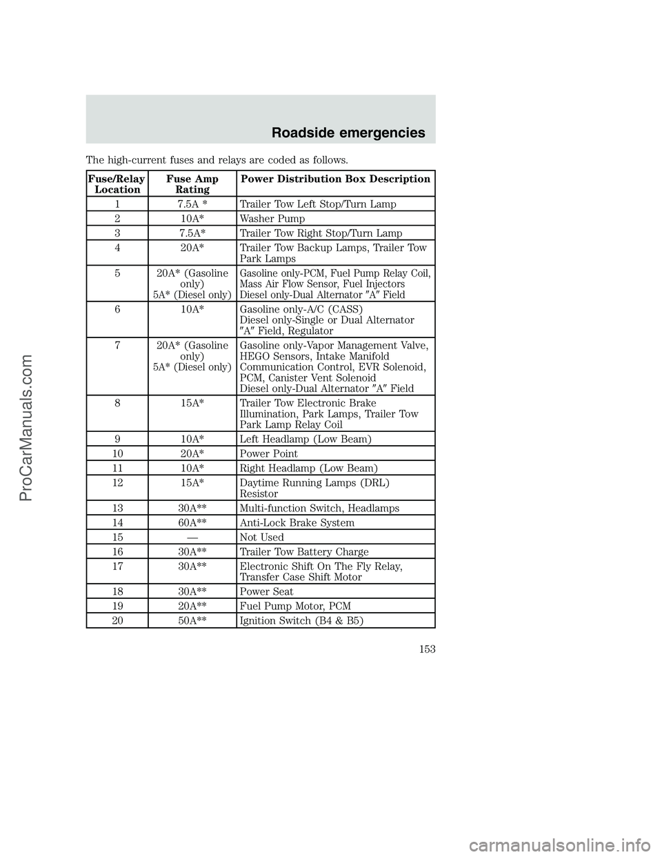
The high-current fuses and relays are coded as follows.
Fuse/Relay
LocationFuse Amp
RatingPower Distribution Box Description
1 7.5A * Trailer Tow Left Stop/Turn Lamp
2 10A* Washer Pump
3 7.5A* Trailer Tow Right Stop/Turn Lamp
4 20A* Trailer Tow Backup Lamps, Trailer Tow
Park Lamps
5 20A* (Gasoline
only)
5A* (Diesel only)Gasoline only-PCM, Fuel Pump Relay Coil,
Mass Air Flow Sensor, Fuel Injectors
Diesel only-Dual Alternator�A�Field
6 10A* Gasoline only-A/C (CASS)
Diesel only-Single or Dual Alternator
�A�Field, Regulator
7 20A* (Gasoline
only)
5A* (Diesel only)
Gasoline only-Vapor Management Valve,
HEGO Sensors, Intake Manifold
Communication Control, EVR Solenoid,
PCM, Canister Vent Solenoid
Diesel only-Dual Alternator�A�Field
8 15A* Trailer Tow Electronic Brake
Illumination, Park Lamps, Trailer Tow
Park Lamp Relay Coil
9 10A* Left Headlamp (Low Beam)
10 20A* Power Point
11 10A* Right Headlamp (Low Beam)
12 15A* Daytime Running Lamps (DRL)
Resistor
13 30A** Multi-function Switch, Headlamps
14 60A** Anti-Lock Brake System
15 — Not Used
16 30A** Trailer Tow Battery Charge
17 30A** Electronic Shift On The Fly Relay,
Transfer Case Shift Motor
18 30A** Power Seat
19 20A** Fuel Pump Motor, PCM
20 50A** Ignition Switch (B4 & B5)
Roadside emergencies
153
ProCarManuals.com
Page 154 of 256

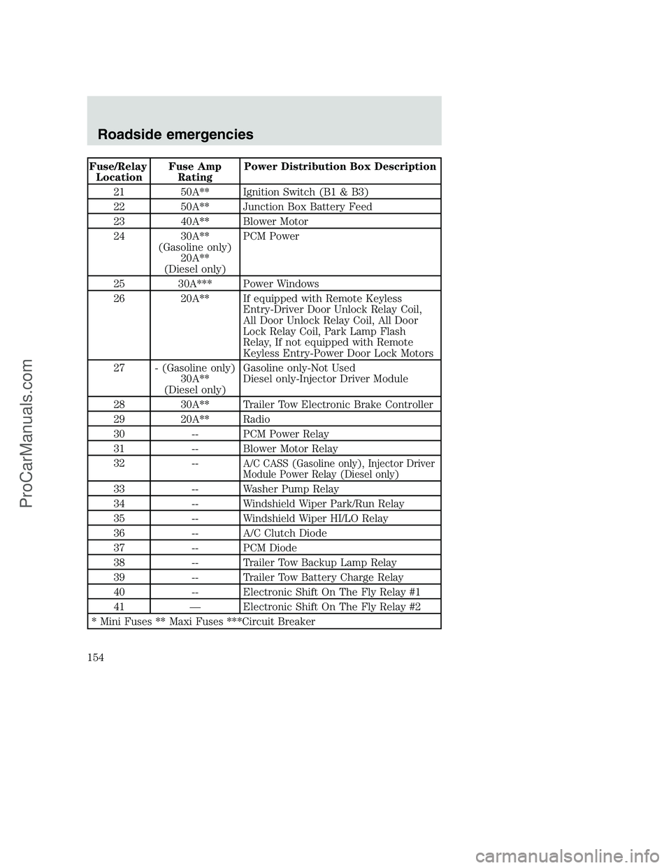
Fuse/Relay
LocationFuse Amp
RatingPower Distribution Box Description
21 50A** Ignition Switch (B1 & B3)
22 50A** Junction Box Battery Feed
23 40A** Blower Motor
24 30A**
(Gasoline only)
20A**
(Diesel only)PCM Power
25 30A*** Power Windows
26 20A** If equipped with Remote Keyless
Entry-Driver Door Unlock Relay Coil,
All Door Unlock Relay Coil, All Door
Lock Relay Coil, Park Lamp Flash
Relay, If not equipped with Remote
Keyless Entry-Power Door Lock Motors
27 - (Gasoline only)
30A**
(Diesel only)Gasoline only-Not Used
Diesel only-Injector Driver Module
28 30A** Trailer Tow Electronic Brake Controller
29 20A** Radio
30 -- PCM Power Relay
31 -- Blower Motor Relay
32 --
A/C CASS (Gasoline only), Injector Driver
Module Power Relay (Diesel only)
33 -- Washer Pump Relay
34 -- Windshield Wiper Park/Run Relay
35 -- Windshield Wiper HI/LO Relay
36 -- A/C Clutch Diode
37 -- PCM Diode
38 -- Trailer Tow Backup Lamp Relay
39 -- Trailer Tow Battery Charge Relay
40 -- Electronic Shift On The Fly Relay #1
41 — Electronic Shift On The Fly Relay #2
* Mini Fuses ** Maxi Fuses ***Circuit Breaker
Roadside emergencies
154
ProCarManuals.com
Page 155 of 256

CHANGING THE TIRES
If you get a flat tire while driving, do not apply the brake heavily.
Instead, gradually decrease your speed. Hold the steering wheel firmly
and slowly move to a safe place on the side of the road.
Spare tire information
Your vehicle may be equipped with a spare tire that can be used as
either a spare or a regular tire. The spare tire is not equipped with wheel
trim. The wheel trim from the original wheel/tire may be used on the
spare.
If your vehicle is equipped with 4WD, a spare tire of a different
size than the road tires should not be used. Such a tire could
result in damage to driveline components and make the vehicle
difficult to control.
Location of the spare tire and tools
The spare tire and tools for your vehicle are stowed in the following
locations:
Tool Location
Spare tire (pick-up
trucks only)Under the vehicle, just forward of the rear
bumper
Jack Regular cab, crew cab and SuperCab without
rear bench seat: Fastened to floor pan behind
rearmost seat on passenger side
SuperCab with rear bench seat: Under rear
bench on passenger side
Jack handle and lug
wrenchOn top of the radiator support at the front of
the engine compartment
Key, spare tire lock (if
equipped)In the glove box
Removing the spare tire (with spare tire carrier only)
1. The following tools are required to remove the spare tire:
•one handle extension and one
typical extension. To assemble,
align button with hole and slide
parts together. To disconnect,
depress button and pull apart.
Roadside emergencies
155
ProCarManuals.com