Page 182 of 280

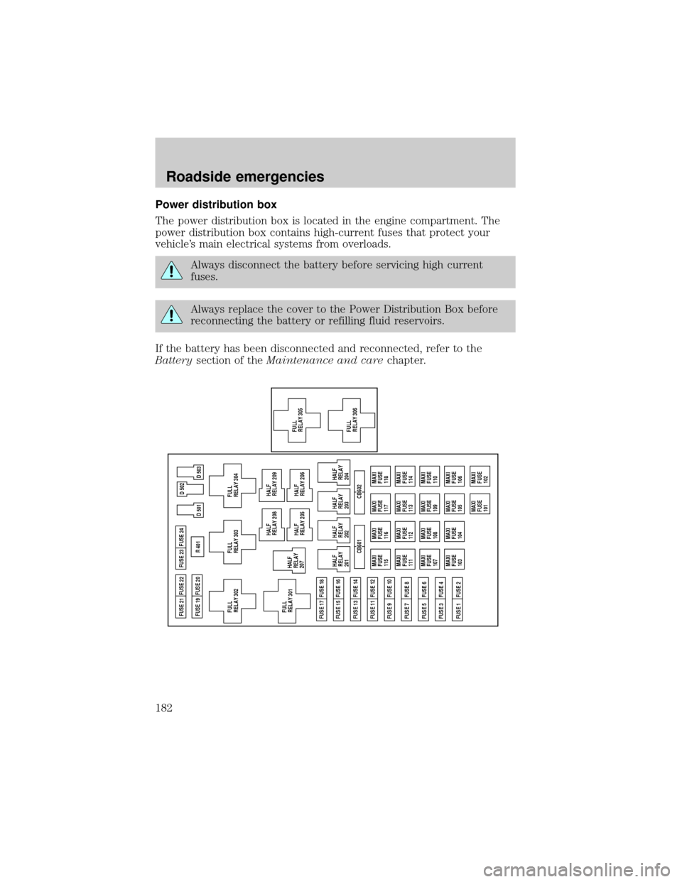
Power distribution box
The power distribution box is located in the engine compartment. The
power distribution box contains high-current fuses that protect your
vehicle's main electrical systems from overloads.
Always disconnect the battery before servicing high current
fuses.
Always replace the cover to the Power Distribution Box before
reconnecting the battery or refilling fluid reservoirs.
If the battery has been disconnected and reconnected, refer to the
Batterysection of theMaintenance and carechapter.
MAXI
FUSE
115MAXI
FUSE
116MAXI
FUSE
117
MAXI
FUSE
118
MAXI
FUSE
111MAXI
FUSE
112MAXI
FUSE
113
MAXI
FUSE
114
MAXI
FUSE
107MAXI
FUSE
108MAXI
FUSE
109
MAXI
FUSE
110
MAXI
FUSE
103MAXI
FUSE
104MAXI
FUSE
105
MAXI
FUSE
106
MAXI
FUSE
101MAXI
FUSE
102 CB601 CB602 FUSE 17 FUSE 18FUSE 21 FUSE 22
FUSE 19 FUSE 20FUSE 23
FULL
RELAY 302R 401
D 501 FUSE 24
FUSE 15 FUSE 16
FUSE 13 FUSE 14
FUSE 11 FUSE 12
FUSE 9 FUSE 10
FUSE 7 FUSE 8
FUSE 5 FUSE 6
FUSE 3 FUSE 4
FUSE 1 FUSE 2
D 503 D 502
FULL
RELAY 301HALF
RELAY
207
FULL
RELAY 305FULL
RELAY 306
FULL
RELAY 303
FULL
RELAY 304
HALF
RELAY
201
HALF
RELAY
202HALF
RELAY 208
HALF
RELAY 209
HALF
RELAY 205
HALF
RELAY 206
HALF
RELAY
203
HALF
RELAY
204
Roadside emergencies
182
Page 184 of 280
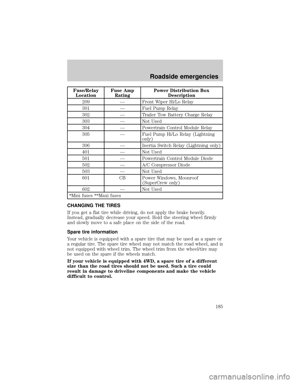
Fuse/Relay
LocationFuse Amp
RatingPower Distribution Box
Description
101 30A** Trailer Tow Battery Charge
102 50/20A** Four Wheel Antilock Brake
Module/Rear Wheel Antilock Brake
Module
103 50A** Junction Block Battery Feed
104 30A** 4x4 Shift Motor & Clutch
105 40A** Climate Control Front Blower
106 20A** Inter Cooler Pump (Lightning only)
107 Ð Not Used
108 30A** Trailer Tow Electric Brake
109 Ð Not Used
110 30A** Power Windows
111 40A** Ignition Switch Battery Feed (Start
and Run Circuits)
112 30A** Drivers Power Seat, Adjustable
Pedals
113 40A** Ignition Switch Battery Feed (Run
and Accessory Circuits)
114 Ð Not Used
115 20A** Power Door Locks (SuperCrew only)
116 Ð Not Used
117 Ð Not Used
118 Ð Not Used
201 Ð Trailer Tow Park Lamp Relay
202 Ð Front Wiper Run/Park Relay
203 Ð Trailer Tow Backup Lamp Relay
204 Ð A/C Clutch Relay
205 Ð Horn Relay
206 Ð Fog Lamp Relay
207 Ð Front Washer Pump Relay
208 Ð Inter Cooler Pump Relay (Lightning
only)
Roadside emergencies
184
Page 185 of 280

Fuse/Relay
LocationFuse Amp
RatingPower Distribution Box
Description
209 Ð Front Wiper Hi/Lo Relay
301 Ð Fuel Pump Relay
302 Ð Trailer Tow Battery Charge Relay
303 Ð Not Used
304 Ð Powertrain Control Module Relay
305 Ð Fuel Pump Hi/Lo Relay (Lightning
only)
306 Ð Inertia Switch Relay (Lightning only)
401 Ð Not Used
501 Ð Powertrain Control Module Diode
502 Ð A/C Compressor Diode
503 Ð Not Used
601 CB Power Windows, Moonroof
(SuperCrew only)
602 Ð Not Used
*Mini fuses **Maxi fuses
CHANGING THE TIRES
If you get a flat tire while driving, do not apply the brake heavily.
Instead, gradually decrease your speed. Hold the steering wheel firmly
and slowly move to a safe place on the side of the road.
Spare tire information
Your vehicle is equipped with a spare tire that may be used as a spare or
a regular tire. The spare tire wheel may not match the road wheel, and is
not equipped with wheel trim. The wheel trim from the wheel/tire may
be used on the spare if the wheels match.
If your vehicle is equipped with 4WD, a spare tire of a different
size than the road tires should not be used. Such a tire could
result in damage to driveline components and make the vehicle
difficult to control.
Roadside emergencies
185
Page 190 of 280

To lessen the risk of
personal injury, do not put
any part of your body under the
vehicle while changing a tire. Do
not start the engine when your
vehicle is on the jack. The jack is
only meant for changing the tire.
²Never use the front or rear
differential as a jacking point.
8. Remove the lug nuts with the lug wrench.
9. Replace the flat tire with the spare tire, making sure the valve stem is
facing outward. Reinstall the lug nuts until the wheel is snug against the
hub. Do not fully tighten the lug nuts until the wheel has been lowered.
10. Lower the wheel by turning the jack handle counterclockwise.
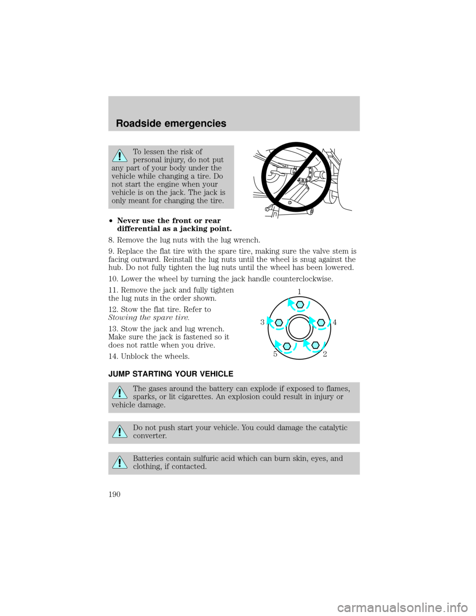
11.
Remove the jack and fully tighten
the lug nuts in the order shown.
12. Stow the flat tire. Refer to
Stowing the spare tire.
13. Stow the jack and lug wrench.
Make sure the jack is fastened so it
does not rattle when you drive.
14. Unblock the wheels.
JUMP STARTING YOUR VEHICLE
The gases around the battery can explode if exposed to flames,
sparks, or lit cigarettes. An explosion could result in injury or
vehicle damage.
Do not push start your vehicle. You could damage the catalytic
converter.
Batteries contain sulfuric acid which can burn skin, eyes, and
clothing, if contacted.
1
4 3
2 5
Roadside emergencies
190
Page 191 of 280

Do not attempt to push start your vehicle. Automatic
transmissions do not have push-start capability.
Preparing your vehicle
When the battery is disconnected or a new battery is installed, the
transmission must relearn its adaptive strategy. As a result of this, the
transmission may shift firmly. This operation is considered normal and
will not effect function or durability of the transmission. Over time, the
adaptive learning process will fully update transmission operation to its
optimum shift feel.
1.Use only a 12±volt supply to start your vehicle.
2. Do not disconnect the battery of the disabled vehicle as this could
damage the vehicle's electrical system.
3.
Park the booster vehicle close to the hood of the disabled vehicle
making sure the two vehiclesdo nottouch. Set the parking brake on both
vehicles and stay clear of the engine cooling fan and other moving parts.
4. Check all battery terminals and remove any excessive corrosion before
you attach the battery cables. Ensure that vent caps are tight and level.
5. Turn the heater fan on in both vehicles to protect any electrical
surges. Turn all other accessories off.
Connecting the jumper cables
1. Connect the positive (+) booster cable to the positive (+) terminal of
the discharged battery.
Note:In the illustrations,lightning boltsare used to designate the
assisting (boosting) battery.
+–+–
Roadside emergencies
191
Page 192 of 280
2. Connect the other end of the positive (+) cable to the positive (+)
terminal of the assisting battery.
3. Connect the negative (-) cable to the negative (-) terminal of the
assisting battery.
4. Make the final connection of the negative (-) cable to an exposed
metal part of the stalled vehicle's engine, away from the battery and the
carburetor/fuel injection system.Do notuse fuel lines, engine rocker
covers or the intake manifold asgroundingpoints.
+–+–
+–+–
+–+–
Roadside emergencies
192
Page 193 of 280
Do not connect the end of the second cable to the negative (-)
terminal of the battery to be jumped. A spark may cause an
explosion of the gases that surround the battery.
5. Ensure that the cables are clear of fan blades, belts, moving parts of
both engines, or any fuel delivery system parts.
Jump starting
1. Start the engine of the booster vehicle and run the engine at
moderately increased speed.
2. Start the engine of the disabled vehicle.
3. Once the disabled vehicle has been started, run both engines for an
additional three minutes before disconnecting the jumper cables.
Removing the jumper cables
Remove the jumper cables in the reverse order that they were
connected.
1. Remove the jumper cable from thegroundmetal surface.
Note:In the illustrations,lightning boltsare used to designate the
assisting (boosting) battery.
+–+–
Roadside emergencies
193
Page 194 of 280
2. Remove the jumper cable on the negative (-) connection of the
booster vehicle's battery.
3. Remove the jumper cable from the positive (+) terminal of the booster
vehicle's battery.
4. Remove the jumper cable from the positive (+) terminal of the
disabled vehicle's battery.
+–+–
+–+–
+–+–
Roadside emergencies
194