2000 FORD F SERIES MOTORHOME AND COMMERCIAL CHASSIS battery location
[x] Cancel search: battery locationPage 43 of 104
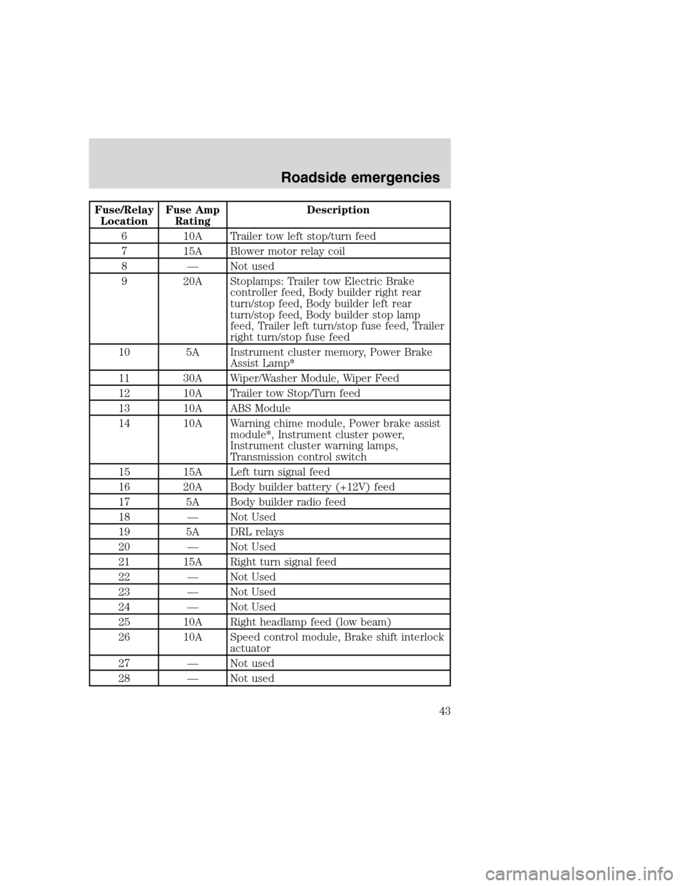
Fuse/Relay
LocationFuse Amp
RatingDescription
6 10A Trailer tow left stop/turn feed
7 15A Blower motor relay coil
8 — Not used
9 20A Stoplamps: Trailer tow Electric Brake
controller feed, Body builder right rear
turn/stop feed, Body builder left rear
turn/stop feed, Body builder stop lamp
feed, Trailer left turn/stop fuse feed, Trailer
right turn/stop fuse feed
10 5A Instrument cluster memory, Power Brake
Assist Lamp*
11 30A Wiper/Washer Module, Wiper Feed
12 10A Trailer tow Stop/Turn feed
13 10A ABS Module
14 10A Warning chime module, Power brake assist
module*, Instrument cluster power,
Instrument cluster warning lamps,
Transmission control switch
15 15A Left turn signal feed
16 20A Body builder battery (+12V) feed
17 5A Body builder radio feed
18 — Not Used
19 5A DRL relays
20 — Not Used
21 15A Right turn signal feed
22 — Not Used
23 — Not Used
24 — Not Used
25 10A Right headlamp feed (low beam)
26 10A Speed control module, Brake shift interlock
actuator
27 — Not used
28 — Not used
Roadside emergencies
43
Page 44 of 104
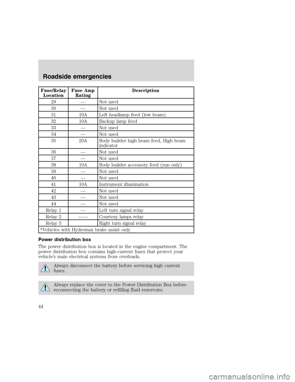
Fuse/Relay
LocationFuse Amp
RatingDescription
29 — Not used
30 — Not used
31 10A Left headlamp feed (low beam)
32 10A Backup lamp feed
33 — Not used
34 — Not used
35 20A Body builder high beam feed, High beam
indicator
36 — Not used
37 — Not used
38 10A Body builder accessory feed (run only)
39 — Not used
40 — Not used
41 10A Instrument illumination
42 — Not used
43 — Not used
44 — Not used
Relay 1 — Left turn signal relay
Relay 2 —— Courtesy lamps relay
Relay 3 Right turn signal relay
*Vehicles with Hydromax brake assist only
Power distribution box
The power distribution box is located in the engine compartment. The
power distribution box contains high-current fuses that protect your
vehicle’s main electrical systems from overloads.
Always disconnect the battery before servicing high current
fuses.
Always replace the cover to the Power Distribution Box before
reconnecting the battery or refilling fluid reservoirs.
Roadside emergencies
44
Page 45 of 104
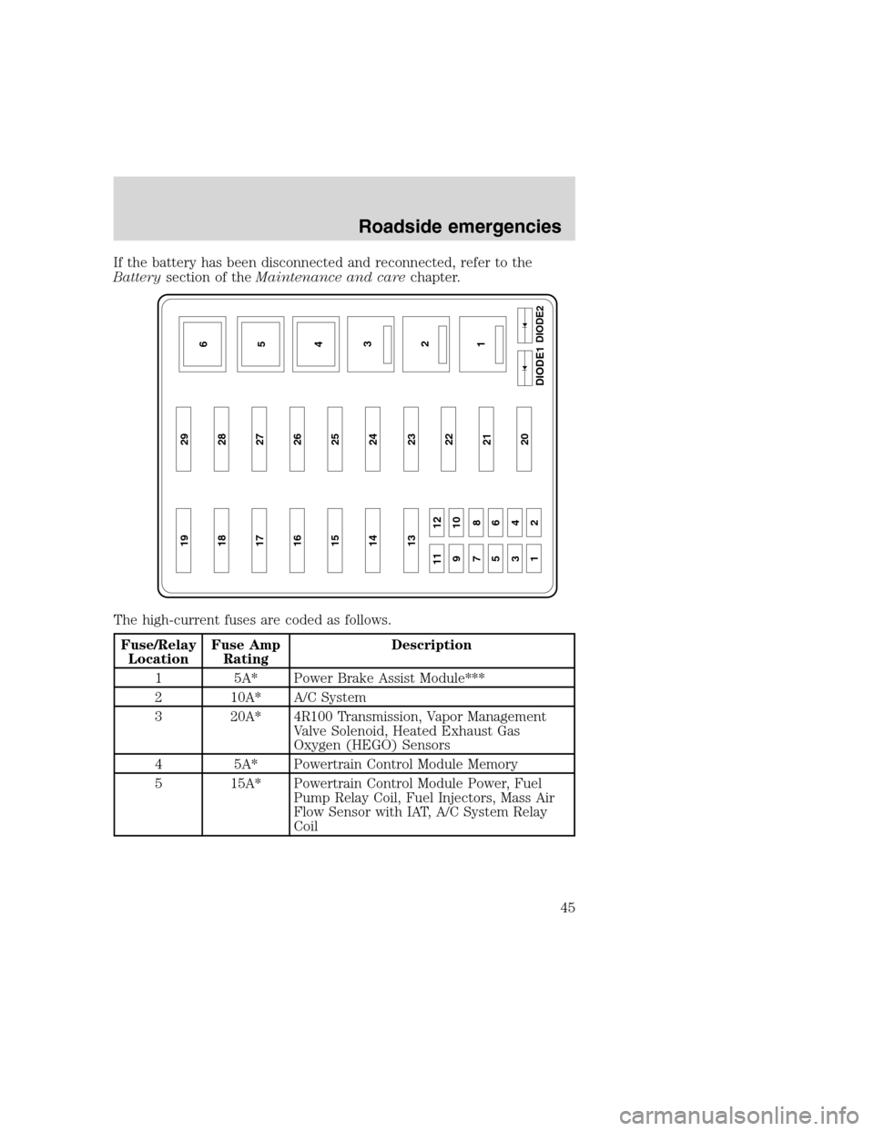
If the battery has been disconnected and reconnected, refer to the
Batterysection of theMaintenance and carechapter.
The high-current fuses are coded as follows.
Fuse/Relay
LocationFuse Amp
RatingDescription
1 5A* Power Brake Assist Module***
2 10A* A/C System
3 20A* 4R100 Transmission, Vapor Management
Valve Solenoid, Heated Exhaust Gas
Oxygen (HEGO) Sensors
4 5A* Powertrain Control Module Memory
5 15A* Powertrain Control Module Power, Fuel
Pump Relay Coil, Fuel Injectors, Mass Air
Flow Sensor with IAT, A/C System Relay
Coil
19 29
18 28
17 27
16 26
15 25
14 24
13
11 12
910
78
56
34
1223
22
21
20
6
5
4
3
2
1DIODE2
DIODE1
Roadside emergencies
45
Page 46 of 104
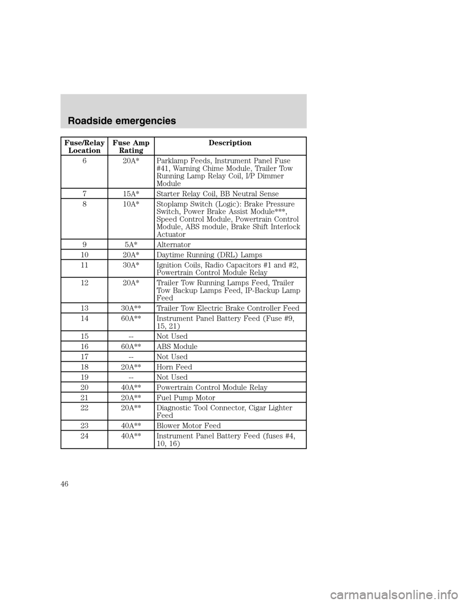
Fuse/Relay
LocationFuse Amp
RatingDescription
6 20A* Parklamp Feeds, Instrument Panel Fuse
#41, Warning Chime Module, Trailer Tow
Running Lamp Relay Coil, I/P Dimmer
Module
7 15A* Starter Relay Coil, BB Neutral Sense
8 10A* Stoplamp Switch (Logic): Brake Pressure
Switch, Power Brake Assist Module***,
Speed Control Module, Powertrain Control
Module, ABS module, Brake Shift Interlock
Actuator
9 5A* Alternator
10 20A* Daytime Running (DRL) Lamps
11 30A* Ignition Coils, Radio Capacitors #1 and #2,
Powertrain Control Module Relay
12 20A* Trailer Tow Running Lamps Feed, Trailer
Tow Backup Lamps Feed, IP-Backup Lamp
Feed
13 30A** Trailer Tow Electric Brake Controller Feed
14 60A** Instrument Panel Battery Feed (Fuse #9,
15, 21)
15 -- Not Used
16 60A** ABS Module
17 -- Not Used
18 20A** Horn Feed
19 -- Not Used
20 40A** Powertrain Control Module Relay
21 20A** Fuel Pump Motor
22 20A** Diagnostic Tool Connector, Cigar Lighter
Feed
23 40A** Blower Motor Feed
24 40A** Instrument Panel Battery Feed (fuses #4,
10, 16)
Roadside emergencies
46
Page 54 of 104
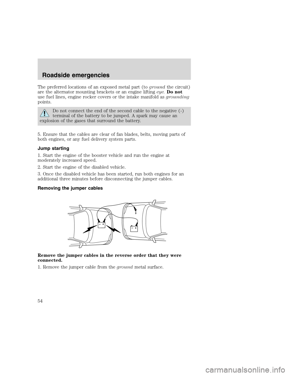
The preferred locations of an exposed metal part (togroundthe circuit)
are the alternator mounting brackets or an engine liftingeye.Do not
use fuel lines, engine rocker covers or the intake manifold asgrounding
points.
Do not connect the end of the second cable to the negative (-)
terminal of the battery to be jumped. A spark may cause an
explosion of the gases that surround the battery.
5. Ensure that the cables are clear of fan blades, belts, moving parts of
both engines, or any fuel delivery system parts.
Jump starting
1. Start the engine of the booster vehicle and run the engine at
moderately increased speed.
2. Start the engine of the disabled vehicle.
3. Once the disabled vehicle has been started, run both engines for an
additional three minutes before disconnecting the jumper cables.
Removing the jumper cables
Remove the jumper cables in the reverse order that they were
connected.
1. Remove the jumper cable from thegroundmetal surface.
+–+–
Roadside emergencies
54
Page 57 of 104
SERVICE RECOMMENDATIONS
To help you service your vehicle:
•We highlight do-it-yourself items in the engine compartment for easy
location.
•We provide a Scheduled Maintenance Guide which makes tracking
routine service easy.
If your vehicle requires professional service, your dealership can provide
necessary parts and service. Check your “Warranty Guide” to find out
which parts and services are covered.
Use only recommended fuels, lubricants, fluids and service parts
conforming to specifications. Motorcraft parts are designed and built to
provide the best performance in your vehicle.
PRECAUTIONS WHEN SERVICING YOUR VEHICLE
Be especially careful when inspecting or servicing your vehicle.
•Do not work on a hot engine.
•When the engine is running, make sure that loose clothing, jewelry or
long hair does not get caught up in moving parts.
•Do not work on a vehicle with the engine running in an enclosed
space, unless you are sure you have enough ventilation.
•Keep all lit cigarettes, open flames and other lit material away from
the battery and all fuel related parts.
If you disconnect the battery, the engine must “relearn” its idle
conditions before your vehicle will drive properly, as explained inBattery
in this chapter.
Working with the engine off
1. Set the parking brake and ensure the gearshift is securely latched in P
(Park).
2. Turn off the engine and remove the key.
3. Block the wheels to prevent the vehicle from moving unexpectedly.
Working with the engine on
1. Set the parking brake and ensure the gearshift is securely latched in P
(Park).
2. Block the wheels to prevent the vehicle from moving unexpectedly.
Maintenance and care
57
Page 99 of 104
filter, specifications .............85,92
gauge .........................................12
improving fuel economy ..........82
low fuel warning light ................6
octane rating ........................81,95
quality ........................................81
running out of fuel ...................82
safety information relating to
automotive fuels .......................79
Fuses .......................................41,42
Gas mileage
(see Fuel economy) ...................82
Gauges .........................................12
battery voltage gauge ...............13
engine coolant
temperature gauge ...................13
engine oil pressure gauge ........12
fuel gauge ..................................12
odometer ...................................14
speedometer .............................14
tachometer ................................15
trip odometer ............................14
GAWR
(Gross Axle Weight Rating) .......33
calculating .................................35
definition ...................................33
driving with a heavy load ........33
location ......................................33
GVWR (Gross Vehicle
Weight Rating) ............................33
calculating ............................33,35
definition ...................................33
driving with a heavy load ........33
location ......................................33
Hazard flashers ...........................39
Headlamps ...................................16
daytime running lights .............16
flash to pass ..............................17
high beam ............................11,16
turning on and off ....................16
warning chime ..........................11
Ignition .........................................95positions of the ignition ...........17
Inspection/maintenance
(I/M) testing ................................89
Instrument panel
cluster ..........................................6
lighting up
panel and interior .....................17
Jump-starting your vehicle ........52
Keys
key in ignition chime ...............11
positions of the ignition ...........17
Lamps
cargo lamps ...............................17
daytime running light ...............16
headlamps .................................16
headlamps, flash to pass ..........17
instrument panel, dimming .....17
replacing bulbs .........................90
Lights, warning and indicator ......6
anti-lock brakes (ABS) .......10,28
brake ............................................7
charging system ..........................7
check coolant ..............................6
door ajar ....................................10
engine oil pressure .....................6
fuel reset ...................................11
high beam .................................11
low fuel ........................................6
safety belt ...................................7
service engine soon .................8,9
turn signal indicator .................11
Load limits ...................................33
GAWR ........................................33
GVWR ........................................33
trailer towing ............................33
Lubricant specifications ........94,95
Motorcraft parts .....................85,92
Octane rating ..............................81
Odometer .....................................14
Overdrive .....................................22
Parking brake ..............................29
Parts (see Motorcraft parts) ......92
Index
99