2000 FIAT MAREA AUX
[x] Cancel search: AUXPage 104 of 330

Engine
Fuel feed system
JTD Marea- Marea Weekend 0
2000 range ©
10.
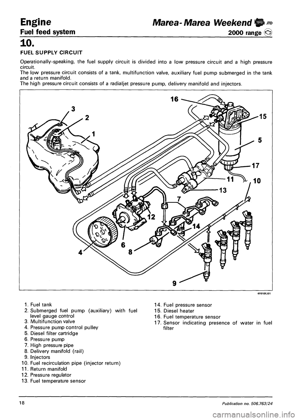
FUEL SUPPLY CIRCUIT
Operationally-speaking, the fuel supply circuit is divided into a low pressure circuit and a high pressure
circuit.
The low pressure circuit consists of a tank, multifunction valve, auxiliary fuel pump submerged in the tank
and a return manifold.
The high pressure circuit consists of a radialjet pressure pump, delivery manifold and injectors.
1. Fuel tank
2. Submerged fuel pump (auxiliary) with fuel
level gauge control
3. Multifunction valve
4. Pressure pump control pulley
5. Diesel filter cartridge
6. Pressure pump
7. High pressure pipe
8. Delivery manifold (rail)
9. Injectors
10. Fuel recirculation pipe (injector return)
11. Return manifold
12. Pressure regulator
13. Fuel temperature sensor
14. Fuel pressure sensor
15. Diesel heater
16. Fuel temperature sensor
17. Sensor indicating presence of water in fuel
filter
18 Publication no. 506.763/24
Page 105 of 330

Marea- Marea Weekend 9 ™
2000 range (Q)
4F019XJ01
1. Impeller
2. Volumes
3. Intake port
4. Outlet port
5. Rollers
6. Outer race
7. Pressure relief valve
4F019XJ02
Engine
Fuel feed system
10.
SUBMERGED FUEL PUMP ASSEMBLY
(AUXILIARY) AND LEVEL GAUGE CON
TROL
The assembly consists mainly of:
- a roller-type fuel pump;
- a fuel level gauge;
- a fuel filter
The submerged fuel pump is volumetric type
with rollers and a motor with brushes and
permanent magnet excitation.
Impeller (1) is driven by the electric motor to
turn and create volumes (2) that move from
intake port (3) to outlet port (4).
These volumes are delimited by rollers (5) that
adhere to outer race(6) as the motor turns.
The pump is fitted with two valves: a check
valve to prevent the fuel circuit emptying
(with the pump off); a second pressure relief
valve (7) that short-circuits the outlet to the
inlet when pressures exceed 5 bars.
FUEL FILTER
The fuel filter is located in the engine bay.
The filter is cartridge type with a filter element
(1) made up of a pack of paper discs with a
filtering area of some 5300 cm 2 and a filter
gauge of 4 - 5 microns.
The filter is equipped with a fuel preheating
device (2) controlled by the engine control
unit via a relay.
The control unit activates or deactivates the
diesel filter on the basis of a diesel tempera
ture signal sent by sensor (3) on the filter.
A plug (4) screwed to the base of the fuel
filter cartridge is used to drai off the water.
The plug incorporates a sensor for the detec
tion of water in the diesel filter connected to a
warning light on the instrument panel.
1. Filter cartridge
2. Diesel preheating device
3. Diesel temperature sensor
4. Water drain plug with sensor to detect
presence of water in diesel filter
Copyright by Fiat Auto 19
Page 106 of 330

Engine
Fuel feed system
JTD Marea-Marea Weekend @
2000 range ©
10.
7^ £3
PRESSURE PUMP
The pressure pump is radialjet type with three
radial pistons (total capacity 0.657 cc). It is
controlled by a timing belt with or without
timing requirements.
Each pump unit consists of:
a piston (5) opered by a cam (2) integral with
the pump shaft (6);
a plate-type intake valve (3);
a delivery ball valve (4).
The pressure pump must be supplied at a
pressure of at least 0.5 bars; and for this rea
son the fuel system is equipped with an aux
iliary pump submerged in the tank.
The pressure pump is lubricated and cooled
by the diesel fuel via channels and is able to
deliver a maximum pressure of 1350 bars.
1.
2.
3.
4.
5.
6.
7.
8.
Cylinder
Cam
Plate-type intake valve
Ball-type delivery valve
Piston
Pump shaft
Diesel intake connection -
from fuel filter
Diesel delivery connection
to manifold (rail)
Diesel delivery connection
recirculation
low pressure
high pressure
low pressure
PRESSURE REGULATOR
FILTER
The fuel pressure regulator is fitted to the
pressure pump and controlled directly by the
injection control unit. It regulates fuel feed
pressure to the injectors.
The pressure regulator consists mainly of the
following parts:
1. Ball plunger
2. Pin
3. Valve
4. Preload spring
5. Coil
6. Body
7. Anchor
20 Publication no. 506.763/24
Page 108 of 330

Engine
Fuel feed system
Marea- Marea Weekend W)JTD
2000 range ©
INERTIA SAFETY SWITCH
To increase car occupant safety in the case of
impact, the car is fitted with an inertia switch
located inside the passenger compartment se
cured to the inside of the left panel.
This sensor reduces the possibility of fire (due
to emerging fuel) by deactivating the auxiliary
fuel pump that supplies the injection circuit.
The switch consists of a steel ball, fitted in a
tapered housing, kept in place by the attrac
tion force of a permanent magnet.
In the case of violent impact, the ball is released from the magnetic detent and opens the normally closed
(NC) electrical circuit to cut off the auxiliary fuel pump connection to earth, and as a consequence the
supply to the injection system.
To restore the auxiliary pump earth connection, move back the seat and press the switch until a click is
heard.
Even after an apparently slight impact, if there is a smell of fuel or there are leaks from the fuel
system, do not turn the switch back on, but search for the fault and remedy it to prevent the risk
of fire.
'N.C. N.A. C
Inertia switch components
1. Inertia switch assembly
2. Sheath
3. Button
4. Upper side
5. Engagement side
6. Permanent magnet
7. Permanent magnet seat
8. Steel ball
C Common terminal
N.C. Normally closed contact
N.A. Normally open contact
22 Publication no. 506.763/24
Page 125 of 330

Marea- Marea Weekend
2000 range CJ
Auxiliary Units
Index
Compressor ( 1596 engine)
Compressor ( 1910 JTD)
Compressor ( 1998 engine)
Specifications
50
page
1
2
3
4
FOR ANYTHING NOT DEALT WITH,
REFER TO THE BASIC MANUAL, SECTION 50.
Copyright by Fiat Auto
Page 126 of 330

Marea- Marea Weekend
2000 range ©
Auxiliary Units
Climate control
50
COMPRESSOR ( 1596 engine)
The compressor fitted on this version is the HR V5 variable capacity type, illustrated in the diagram below,
and consists of:
- a crankcase (7) which contains the bores in which the pistons (4) slide;
- an assembly comprising a shaft on which an inclined plate (6) is fitted on which a disc (2) guided by
a pin (5) integral with the five connecting rods (3) controlled by the pistons (4) rotates on roller bear
ings;
- a cylinder head which contains the intake and supply ducts as well as the housing for the regulation
valve (9);
- a plate (8), between the crankcase and the cylinder head, which contains the inlet and supply valves;
- a pulley assembly with an electro-magnet coupling (1).
1. Pulley with coupling
2. Disc
3. Connecting rod
4. Piston
5. Disc guide pin
6. Inclined plate
7. Crankcase
8. Valve holder plate
9. Regulation valve
10. Valve control bellows
Operation
The alternating drive required for the sliding of the pistons in the bores/liners is produced by the rotary
motion of the inclined plate (6), whilst the variation in the capacity, dependent on the piston stroke, is
chieved through the alteration in the angle of the disc (2) controlling the connecting rods (3).
The inclination of the above mentioned disc depends on the difference in pressure between the intake
duct and the inside of the compressor. This difference, measured by the bellows (10), operates the regu
lation valve (9) and consequently causes the movement of the disc (2).
When the request for conditioned air is high, the regulation valve (9) is positioned in such a way that it
uncovers an opening which places the intake side in contact with the inside of the compressor; as, in this
case, there is no difference in pressure, the compressor operates at maximum capacity corresponding to
the position of the disc illustrated in the previous section.
When the air request is less, the valve is positioned so that the supply section is in contact with the crank
case and, at the same time, it stops the flow between the latter and the intake side activated previously.
Copyright by Fiat Auto 1
Page 127 of 330

Auxiliary Units
Climate control
Marea-Marea Weekend
2000 range O
50
COMPRESSOR (1910 JTD)
The compressor fitted on this version is the SANDEN SD7V16 variable capacity type.
The capacity of the compressor varies starting from the maximum value (161.3 cm^/rev) and is gradually
reduced (up to 10.4 cm^/rev) according to the system load variations. - changed outside temperature
and/or humidity conditions or sharp variations in the engine load.
This solution is defined as "unlimited variable capacity".
The compressor is the alternating piston type: the variation in capacity is achieved by tilting the connect
ing rod holder plate with a consequent variation of the piston stroke: the movement of the plate is acti
vated by an internal regulation valve according to the balance of pressure upstream and downstream of
the compressor. In particular, a low intake pressure involves the shuttering of the compressor (reduced ca
pacity), whilst a high pressure involves operation at maximum power (maximum capacity).
7 6 4 3 2
5 9
1 Diaphgram valve
2 Pistons
3 Connecting rods
4 Connecting rod plate
5 Shaft
6 Pin
7 Arm
8 Slide
9 Guide
Pa Intake pressure
Pi Pressure inside the compressor
Pm Supply pressure
Operation
The SD7V16 compressor is illustrated in the diagram; it consists of seven pistons (2) and connecting rods
(3) fastened to a connecting rod holder plate (4). The rotary motion of the plate (4), on the shaft (5)
produces the alternating movement of the pistons.
A change in the plate angle allows an alteration in capacity: maximum inclination (as in the diagram) for
maximum capacity; almost zero inclination (vertical position) for minimum capacity (virtually nil).
The plate (4) rotates around the pin (6) hinged on the shaft (5) arm (7).
The movement of the plate (4) in relation to the shaft (5) takes place by means of splining made from a
low resistance material.
The plate (4) slides below along a guide (9) via a runner (8) made from a low friction material.
The diaphragm valve (1) controls the flow rate adjustment according to the difference between Pa (intake
pressure) and Pi (pressure inside the compressor).
N.B. the solution adopted for this compressor is designed to keep the internal pressure Pi constant, with
advantages in terms of ease of adjustment and quiet, smooth operation.
2 Print n° 506.763/23
Page 128 of 330

Marea-Marea Weekend
2000 range ©)
Auxiliary Units
Climate control
50
COMPRESSOR ( 1998 engine)
The compressor fitted on this version is the SANDEN SD6V12 variable capacity type.
The capacity of the compressor varies starting from the maximum value (125.1 cnrfVrev) and is gradually
reduced (up to 6.2 cm /rev) according to the system load variations. - changed outside temperature
and/or humidity conditions or sharp variations in the engine load.
This solution is defined as "unlimited variable capacity".
The compressor is the alternating piston type: the variation in capacity is achieved by tilting the connect
ing rod holder plate with a consequent variation of the piston stroke: the movement of the plate is acti
vated by an internal regulation valve according to the balance of pressure upstream and downstream of
the compressor. In particular a low intake pressure involves the shuttering of the compressor (reduced ca
pacity), whilst a high pressure involves operation at maximum power (maximum capacity).
1. Diaphgram valve
2. Pistons
3. Connecting rods
4. Connecting rod plate
5. Shaft
6. Pin
7. Arm
8. Slide
9. Guide
Operation
The operation is the same as described for the previous SANDEN 7V16 compressor.
Copyright by Fiat Auto 3