2000 FIAT MAREA Ok pump
[x] Cancel search: Ok pumpPage 45 of 330

Technical Data
Braking system
Marea- Marea Weekend
2000 range @>
00.33
FRONT BRAKES
M16v
Values in mm
0
Disc
permitted
283.800 - 284.200
21.800 - 22.100
20.55
20.20
1
Brake
pads allowed 1.5
£ Caliper 0 54
Master cylinder
(pump) 0 23.81 (15/16")
Brake servo
Iso-Vac 8" + 7"
pneumatic vacuum
acting on all four wheels
Distance of hydraulic pis
ton push rod from master
L cylinder support plate
22.45 - 22.65
REAR BRAKES
0 II II Disc
0
allowed
240
10.80 + 11.10
10.10
9.20
Brake
"^s Pads allowed 1.5
0 Shoe 0 34
Load proportioning valve
(•)
Ratio (reduction)
acting on rear wheels
0.36
(•) Not fitted on versions with ABS
38 Print n° 506.763/23
Page 68 of 330

Marea- Marea Weekend • *» Engine
2000 range (§) Fuel feed system
10.
Pages
FUEL FEED SYSTEM
- Engine management system 1
- Diagram showing engine exhaust assem
bly 1
- Fuel anti-evaporation system ~2
- Location of diagnostic socket 2
- Location of injection/ignition system
components in the engine compartment 3
- Front Lambda sensor . 4
- Rear Lambda sensor 4
- Catalytic converter heat shield 5
- Catalytic converter 5
- Exhaust manifold 6
- Electric fuel pump with level sender unit 7
Copyright by Fiat Auto
Page 74 of 330

Engine
Fuel feed system
16v Marea- Marea Weekend ©
2000 range @
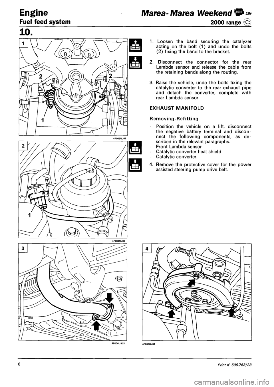
1. Loosen the band securing the catalyzer
acting on the bolt (1) and undo the bolts
(2) fixing the band to the bracket.
2. Disconnect the connector for the rear
Lambda sensor and release the cable from
the retaining bands along the routing.
3. Raise the vehicle, undo the bolts fixing the
catalytic converter to the rear exhaust pipe
and detach the converter, complete with
rear Lambda sensor.
EXHAUST MANIFOLD
Removing-Refitting
- Position the vehicle on a lift, disconnect
the negative battery terminal and discon
nect the following components, as de
scribed in the relevant paragraphs.
- Front Lambda sensor
- Catalytic converter heat shield
- Catalytic converter.
4. Remove the protective cover for the power
assisted steering pump drive belt.
6 Print n° 506.763/23
Page 75 of 330

Marea- Marea Weekend •
2000 range ©
16v Engine
Fuel feed system
10.
1. Loosen the belt tension using the lock nut
(2) and the adjustment screw (1); then re
lease the belt from the pulley.
2. Undo the bolts fixing the bracket for the
power assisted steering pump mounting
and detach the pump.
3. Undo the nuts fixing the exhaust manifold
to the cylinder head and detach the mani
fold.
- To refit, reverse the order of the operations
carried out for the removal; tension the
power assisted steering pump drive belt,
using the adjustment screw; use tool
189576200 to check that the tension is
between 32 and 45 daN.
ELECTRIC FUEL PUMP WITH LEVEL
SENDER UNIT
Removing-refitting
- Disconnect the negative battery terminal.
- Lift up the lining in the luggage compart
ment and remove the fuel pup protective
cover.
- Disconnect the electrical connection for the
electric pump assembly and the fuel supply
and breather pipes.
4. Undo the ring nut fixing the electric fuel
pump to the tank using tool 1870736000.
The gasket on the tank housing should be
replaced each time the pump drip tray is
removed-refitted.
NOTE The position of the fuel pump is fixed
and is established by a reference in
the housing in the tank which sou Id
correspond to the projection on the
pump drip tray.
Copyright by Fiat Auto 7
Page 86 of 330

Marea- Marea Weekend 9 \) JTD
2000 range O
Engine
Index
FUEL SYSTEM
- Introduction
- System management strategies
- Fuel system functional diagram
- Diagram showing information ente
ring/leaving the control unit and
sensors/actuators
INJECTION SYSTEM WIRING DIA
GRAM
- Injection electronic control unit
- Rpm sensor
- Timing sensor
- Air flow meter
- Injectors
- Engine coolant temperature sensor
- Fuel temperature sensor
- Fuel pressure sensor
- Heater plugs control unit
- Accelerator pedal potentiometer
- Brake pedal switch
- Clutch pedal switch
- Excess pressure sensor
- Atmospheric pressure sensor
page
1
1
1
2
8
10
12
13
13
14
15
15
15
16
16
17
17
17
17
THROTTLE CASING
- Removing-refitting
E.G.R. VALVE
- Removing-refitting
E.G.R. VALVE SELF-ADJUSTMENT
MOTOR
- Removing-refitting
E.G.R. VALVE HEAT EXCHANGER
- Removing-refitting
SOLENOID VALVE ON VACUUM
RESERVOIR FOR THROTTLE CA
SING PNEUMATIC VALVE
- Removing-refitting
VACUUM RESERVOIR
- Removing-refitting
10.
page
30
31
32
32
34
34
FUEL SUPPLY CIRCUIT 18
- Immersed (auxiliary) pump and fuel
gauge assembly 19
- Fuel filter 19
- Pressure pump 20
- Fuel pressure regulator 20
- Multifunction valve 21
- Supply manifold (rail) 21
- Inertia safety switch 22
AIR SUPPLY CIRCUIT 23
- Throttle case 24
- Turbocharger 25
SUPERCHARGING PRESSURE
CONTROL SOLENOID VALVE
- Removing-refitting 35
FUEL FILTER
- Removing-refitting 35
PRESSURE REGULATOR
- Removing-refitting 36
EMISSION CONTROL DEVICES 27
- Oxidizing catalytic converter 27
- Exhaust gas recirculation circuit
(EGR) 27
- Recirculation circuit for crankcase
vapours (blow-by) 29
Copyright by Fiat Auto VI 01 Cancels anil replaces
Page 87 of 330

Marea- Marea Weekend © ™ Engine
2000 range Q Fuel feed system
10.
FUEL SYSTEM
INTRODUCTION
Marea and Marea Weekend 1.9 JTD cars are equipped with a 4 cylinder in line, 1910 cc turbodiesel en
gine with two valves per cylinder, an overhead camshaft, turbocharger and intercooler and electronic in
jection.
The fuel system ensures correct engine operation and can be divided into the following subsystems:
- Fuel feed circuit with common rail injection;
- air feed circuit;
- exhaust circuit;
- blow by vapour recirculation circuit;
- Exhaust Gas Recirculation (EGR) circuit
Operation of the various circuits making up the fuel system is optimised by an electronic control system
managed by a special control unit.
The main feature of the fuel system is common rail fuel injection. Common rail is a higher pressure elec
tronic injection system for fast direct injection diesel engines.
The main features of the common rail system are as follows:
- availability of high injection pressures (up to 1350 bars);
- possibility of modulating these pressures (from a minimum of 150 bars to a maximum of 1350 bars)
independently of engine speed (rpm) and engine load;
- ability to operate at high engine speeds (up to 6000 rpm);
- precise injection control (injection advance and duration);
- reduced fuel consumption;
- reduced emissions.
FUEL SYSTEM MANAGEMENT STRATEGIES
The management program (software) is stored inside the control unit memory and consists of a series of
strategies, each of which manages a precise system control function.
Through the use of information providd by the various sensors (input), each strategy processes a set of
parameters based on data stored in special control unit memory areas. It then controls system actuators
(output), i.e. the devices that allow the engine to operate.
The main purpose of these management strategies is to determine the exact amount of fuel to be injected
into the cylinders with timing (injection advance) and pressure designed to achieve the best possible en
gine performance in terms of power, fuel consumption, fumes, emissions and handling.
The main system management strategies are essentially as follows:
contro
contro
contro
contro
contro
contro
contro
contro
contro
contro
contro
contro
contro
contro
contro
of injected fuel quantity;
of injection advance;
of injection pressure;
of auxiliary fuel pump;
of injection during over-run (cut-off);
of idle speed;
of maximum speed limitation;
of maximum torque limitation;
of fuel temperature;
of engine coolant temperature;
of air turbocharging pressure;
of glow plugs;
of exhaust fumes;
of exhaust gas recirculation (EGR);
of climate control system activation;
control of engine immobiliser operation (Fiat
CODE);
self-diagnosis
Copyright by Fiat Auto 1
Page 88 of 330

Engine
Fuel feed system
Marea- Marea Weekend © ™
2000 range ©
10.
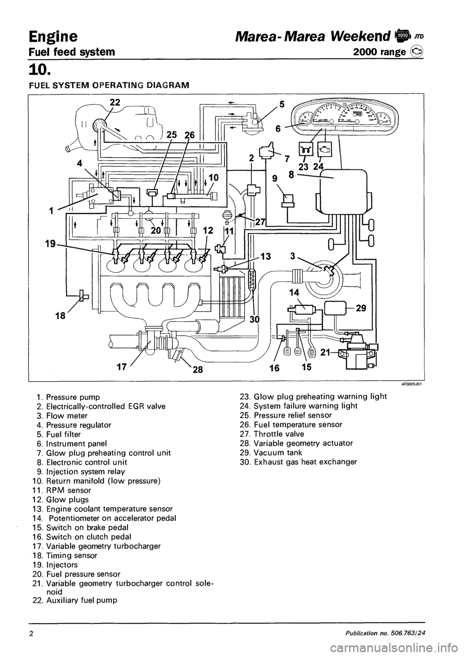
FUEL SYSTEM OPERATING DIAGRAM
1. Pressure pump
2. Electrically-controlled EGR valve
3. Flow meter
4. Pressure regulator
5. Fuel filter
6. Instrument panel
7. Glow plug preheating control unit
8. Electronic control unit
9. Injection system relay
10. Return manifold (low pressure)
11. RPM sensor
12. Glow plugs
13. Engine coolant temperature sensor
14. Potentiometer on accelerator pedal
15. Switch on brake pedal
16. Switch on clutch pedal
17. Variable geometry turbocharger
18. Timing sensor
19. Injectors
20. Fuel pressure sensor
21. Variable geometry turbocharger control sole
noid
22. Auxiliary fuel pump
23. Glow plug preheating warning light
24. System failure warning light
25. Pressure relief sensor
26. Fuel temperature sensor
27. Throttle valve
28. Variable geometry actuator
29. Vacuum tank
30. Exhaust gas heat exchanger
2 Publication no. 506.763/24
Page 89 of 330

Ma tea- Marea Weekend 9 ™
2000 range (Q) Fuel feed system
Engine
10.
Control of injected fuel quantity
The control unit controls the fuel pressure regulator and injectors on the basis of output signals from the
accelerator pedal potentiometer, flow meter and rpm sensor.
The timing and thus the injection sequence are determined when the engine is started up using signals
from the rpm and timing sensor (synchronisation stage); injection timing is then implemented using the
rpm sensor signal alone and considering a injection sequence of 1 -3-4-2.
The control unit inhibits injection in the following cases:
- fuel pressure level greater than 1500 bars;
- fuel pressure level lower than 120 bars;
- engine speed higher than 6000 rpm.
When the engine has warmed up, maximum injection duration (injector opening time) is 1500 ns, but it
can reach 3000 ns during the start-up stage.
Control of injection advance
The electronic control unit determines injection advance mainly on the basis of the quantity of fuel to be
injected.
The injection advance is then corrected on the basis of coolant temperature and speed in order to com
pensate for ignition delays due to low temperatures in the combustion chamber during warm-up.
The optimum injection point is also processed to ensure driving comfort and emission limits laid down by
Euro 3 legislation.
Control of injection pressure
This control is of particular importance because injection pressure influences the following parameters:
- amount of fuel taken into the cylinders for the same injection time duration;
- injected fuel nebulation;
- spray penetration;
- lag between electrical control to injection and actual injection start and end times.
The above parameters engine behaviour significantly, particularly in terms of power output, exhaust emis
sions, noise levels and handling.
The injection control unit controls the pressure governor on the basis of engine load to obtain an optimal
line pressure at all times.
When the engine is cold, injection pressure is corrected on the basis of engine speed and engine coolant
temperature to meet engine needs at different operating temperatures.
Control of auxiliary fuel pump
The auxiliary fuel pump submerged in the tank is supplied by the injection control unit by means of a relay
when the ignition key is turned on.
Fuel supply to the pump is inhibited when one of the following condition occurs:
- when the ignition has been turned on for a certain length of time without the engine running;
- if the inertia switch cuts in.
Control of injection during over-run (cut-off)
The fuel cut-off strategy is implemented when the injection control unit receives information that the ac
celerator pedal has been released from the potentiometer.
Under these conditions, the control unit cuts off the fuel supply to the injectors and restores it before idle
speed is reached.
Copyright by Fiat Auto 3