Page 13 of 37
13
ENGINE COOLING SYSTEM
The cooling system concepts introduced in
the 1999 Model year including the automatic
transmission heat exchanger and the the
water cooled alternator have been retained
for the X5.
The component locations have however
been changed:
• Thermostat for heat exchanger mounted
directly on radiator
• Transmission heat exchanger - right side
of radiator.
Page 15 of 37
15
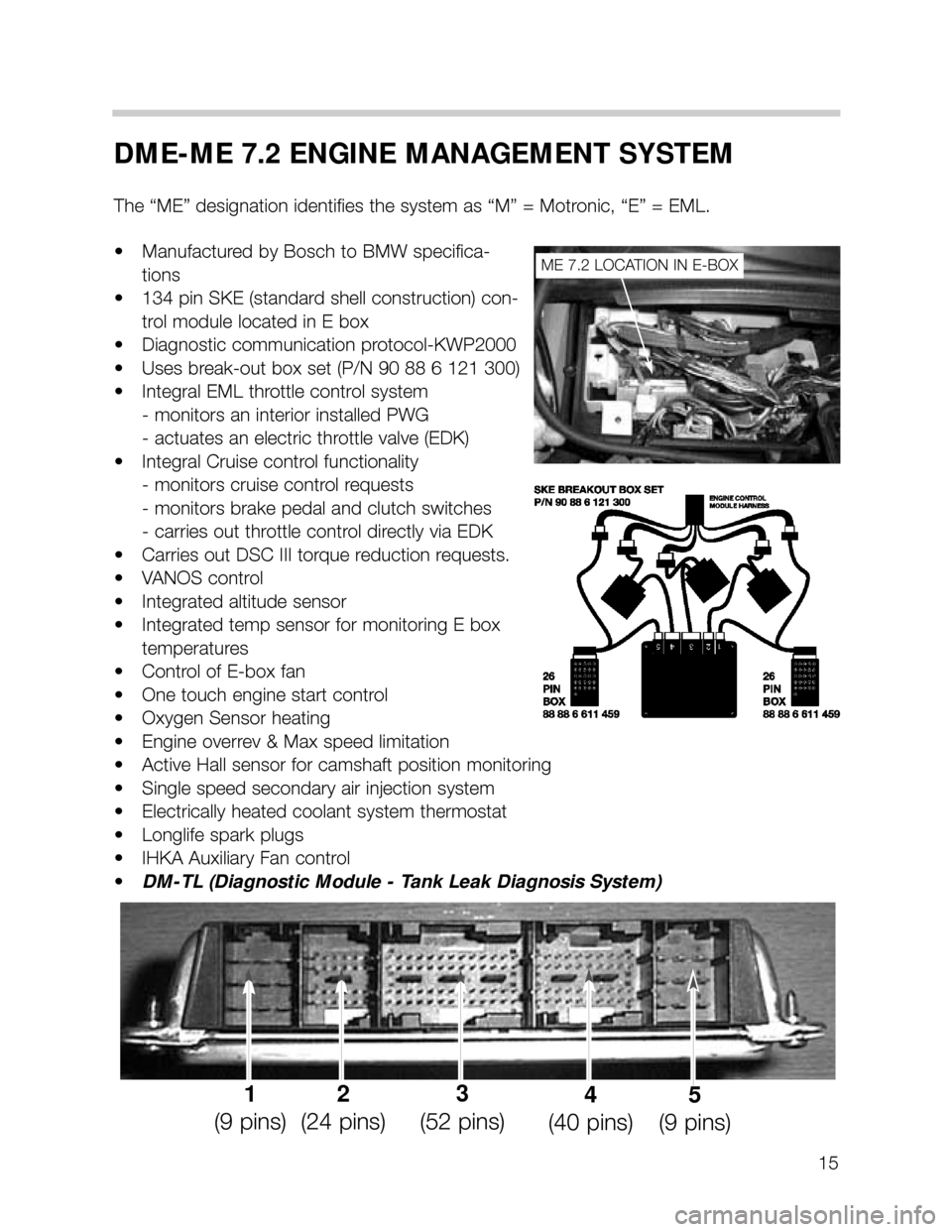
DME-ME 7.2 ENGINE MANAGEMENT SYSTEM
The “ME” designation identifies the system as “M” = Motronic, “E” = EML.
• Manufactured by Bosch to BMW specifica-
tions
• 134 pin SKE (standard shell construction) con-
trol module located in E box
• Diagnostic communication protocol-KWP2000
• Uses break-out box set (P/N 90 88 6 121 300)
• Integral EML throttle control system
- monitors an interior installed PWG
- actuates an electric throttle valve (EDK)
• Integral Cruise control functionality
- monitors cruise control requests
- monitors brake pedal and clutch switches
- carries out throttle control directly via EDK
• Carries out DSC III torque reduction requests.
• VANOS control
• Integrated altitude sensor
• Integrated temp sensor for monitoring E box
temperatures
• Control of E-box fan
• One touch engine start control
• Oxygen Sensor heating
• Engine overrev & Max speed limitation
• Active Hall sensor for camshaft position monitoring
• Single speed secondary air injection system
• Electrically heated coolant system thermostat
• Longlife spark plugs
• IHKA Auxiliary Fan control
•DM-TL (Diagnostic Module - Tank Leak Diagnosis System)
ME 7.2 LOCATION IN E-BOX
1
(9 pins)2
(24 pins)3
(52 pins)4
(40 pins)5
(9 pins)
Page 17 of 37
17
INTEGRAL ELECTRIC THROTTLE SYSTEM (EML)
FUNCTIONAL DESCRIPTION
When the accelerator pedal
is moved, the PWG pro-
vides a change in the mon-
itored signals. The ME 7.2
compares the input signal
to a programmed map and
appropriately activates the
EDK motor via proportional-
ly high/low switching cir-
cuits. The control module
self-checks it’s activation of
the EDK motor via the EDK
feedback potentiometers.
Requirements placed on the Electric Throttle System:
• Regulate the calculated intake air load based on PWG input signals and programmed
mapping.
• Control idle air when LL detected with regard to road speed as per previous systems.
• Monitor the driver’s input request for cruise control operation.
• Automatically position the EDK for accurate cruise control (FGR) operation.
• Perform all DSC III throttle control interventions.
• Monitor and carryout max engine and road speed cutout.
Page 18 of 37
18
PWG SIGNAL MONITORING & PWG FAILSAFE OPERATION:
• As a redundant safety feature the PWG provides two separate signals from two integral
potentiometers (Pot 1 and Pot 2) representing the driver’s request for throttle activation.
• If the monitored PWG potentiometer signals are not plausible, ME 7.2 will only use the
lower of the two signals as the driver’s pedal request input providing failsafe operation.
Throttle response will be slower and maximum throttle position will be reduced.
• When in PWG failsafe operation, ME 7.2 sets the EDK throttle plate and injection time
to idle (LL) whenever the brake pedal is depressed.
• When the system is in PWG failsafe operation, the instrument cluster matrix display will
post “Engine Emergency Program” and PWG specific fault(s) will be stored in memory.
EDK FEEDBACK SIGNAL MONITORING & EDK FAILSAFE OPERATION:
• The EDK provides two separate signals from two integral potentiometers (Pot 1 and Pot
2) representing the exact position of the throttle plate.
• EDK Pot 1 provides the primary throttle plate position feedback. As a redundant safe-
ty feature, Pot 2 is continuously cross checked with Pot 1 for signal plausibility.
• If plausibility errors are detected between Pot 1 and Pot 2, ME 7.2 will calculate the
inducted engine air mass (from HFM signal) and only utilize the potentiometer signal that
closely matches the detected intake air mass.
- The ME 7.2 uses the air mass signalling as a “virtual potentiometer” (pot 3) for a
comparative source to provide failsafe operation.
- If ME 7.2 cannot calculate a plausible conclusion from the monitored pots (1 or 2
and virtual 3) the EDK motor is switched off and fuel injection cut out is activated
(no failsafe operation possible).
• The EDK is continuously monitored during all phases of engine operation. It is also
briefly activated when KL 15 is initially switched on as a “pre-flight check” to verify it’s
mechanical integrity (no binding, appropriate return spring tension, etc). This is accom-
plished by monitoring both the motor control amperage and the reaction speed of the
EDK feedback potentiometers. If faults are detected the EDK motor is switched off and
fuel injection cut off is activated (no failsafe operation possible). The engine does how-
ever continue to run extremely rough at idle speed.
• When a replacement EDK is installed, the ME 7.2 adapts to the new component
(required amperage draw for motor control, feedback pot tolerance differences, etc).
This occurs immediately after the next cycle of KL 15 for approximately 30 seconds.
During this period of adaptation, the maximum opening of the throttle plate is 25%.
Page 19 of 37
19
INPUT SIGNALS/COMPONENTS
CAMSHAFT POSITION SENSORS
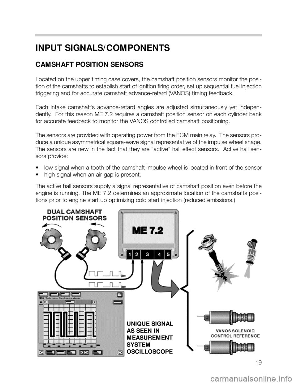
Located on the upper timing case covers, the camshaft position sensors monitor the posi-
tion of the camshafts to establish start of ignition firing order, set up sequential fuel injection
triggering and for accurate camshaft advance-retard (VANOS) timing feedback.
Each intake camshaft’s advance-retard angles are adjusted simultaneously yet indepen-
dently. For this reason ME 7.2 requires a camshaft position sensor on each cy linder bank
for accurate feedback to monitor the VANOS controlled camshaft positioning.
The sensors are provided with operating power from the ECM main relay. The sensors pro-
duce a unique asymmetrical square-wave signal representative of the impulse wheel shape.
The sensors are new in the fact that they are “active” hall effect sensors. Active hall sen-
sors provide:
• low signal when a tooth of the camshaft impulse wheel is located in front of the sensor
• high signal when an air gap is present.
The active hall sensors supply a signal representative of camshaft position even before the
engine is running. The ME 7.2 determines an approximate location of the camshafts posi-
tions prior to engine start up optimizing cold start injection (reduced emissions.)
UNIQUE SIGNAL
AS SEEN IN
MEASUREMENT
SYSTEM
OSCILLOSCOPE
Page 23 of 37
23
ACCELERATOR PEDAL SENSOR (PWG)
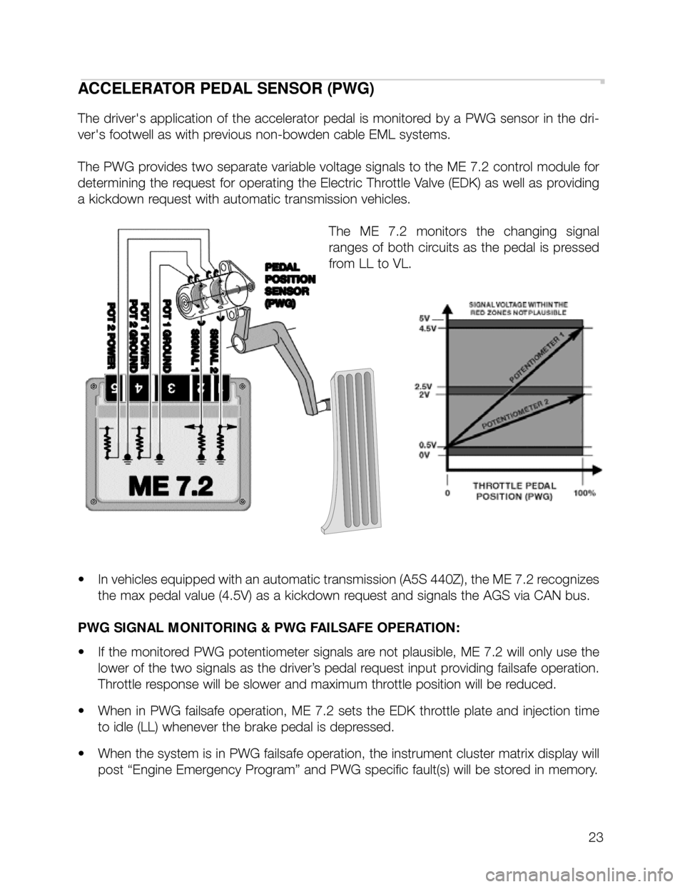
The driver's application of the accelerator pedal is monitored by a PWG sensor in the dri-
ver's footwell as with previous non-bowden cable EML systems.
The PWG provides two separate variable voltage signals to the ME 7.2 control module for
determining the request for operating the Electric Throttle Valve (EDK) as well as providing
a kickdown request with automatic transmission vehicles.
The ME 7.2 monitors the changing signal
ranges of both circuits as the pedal is pressed
from LL to VL.
• In vehicles equipped with an automatic transmission (A5S 440Z), the ME 7.2 recognizes
the max pedal value (4.5V) as a kickdown request and signals the AGS via CAN bus.
PWG SIGNAL MONITORING & PWG FAILSAFE OPERATION:
• If the monitored PWG potentiometer signals are not plausible, ME 7.2 will only use the
lower of the two signals as the driver’s pedal request input providing failsafe operation.
Throttle response will be slower and maximum throttle position will be reduced.
• When in PWG failsafe operation, ME 7.2 sets the EDK throttle plate and injection time
to idle (LL) whenever the brake pedal is depressed.
• When the system is in PWG failsafe operation, the instrument cluster matrix display will
post “Engine Emergency Program” and PWG specific fault(s) will be stored in memory.
Page 24 of 37
24
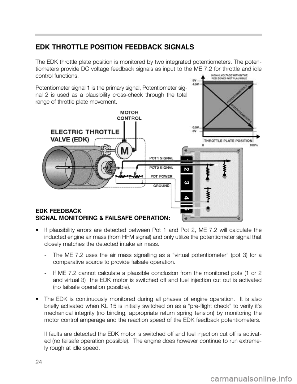
EDK THROTTLE POSITION FEEDBACK SIGNALS
The EDK throttle plate position is monitored by two integrated potentiometers. The poten-
tiometers provide DC voltage feedback signals as input to the ME 7.2 for throttle and idle
control functions.
Potentiometer signal 1 is the primary signal, Potentiometer sig-
nal 2 is used as a plausibility cross-check through the total
range of throttle plate movement.
EDK FEEDBACK
SIGNAL MONITORING & FAILSAFE OPERATION:
• If plausibility errors are detected between Pot 1 and Pot 2, ME 7.2 will calculate the
inducted engine air mass (from HFM signal) and only utilize the potentiometer signal that
closely matches the detected intake air mass.
- The ME 7.2 uses the air mass signalling as a “virtual potentiometer” (pot 3) for a
comparative source to provide failsafe operation.
- If ME 7.2 cannot calculate a plausible conclusion from the monitored pots (1 or 2
and virtual 3) the EDK motor is switched off and fuel injection cut out is activated
(no failsafe operation possible).
• The EDK is continuously monitored during all phases of engine operation. It is also
briefly activated when KL 15 is initially switched on as a “pre-flight check” to verify it’s
mechanical integrity (no binding, appropriate return spring tension) by monitoring the
motor control amperage and the reaction speed of the EDK feedback potentiometers.
If faults are detected the EDK motor is switched off and fuel injection cut off is activat-
ed (no failsafe operation possible). The engine does however continue to run extreme-
ly rough at idle speed.
Page 26 of 37
26
CAN BUS
• The CAN bus consists entirely of a twisted pair wire set. This configuration eliminates
the need for a ground shield.
• The Engine Control Module has two CAN bus communication ports, one dedicated to
AGS and the other for the balance of the vehicle’s CAN bus control modules.
• This configuration improves the reliability of CAN bus signalling. If an open occurs in one
area, the other control systems can still communicate on either side of the open.
• However, signals not reaching their intended recipients will cause CAN bus faults to be
stored in the affected systems.