2000 BMW 540i Bolt Torque
[x] Cancel search: Bolt TorquePage 17 of 1002

Downloaded from www.Manualslib.com manuals search engine
General
ADVICE FOR THE BEGINNER
The tips that follow are general advice to help the do-it-your-
self BMW owner
periorm repairs and maintenance taslts
more easily and more professionally.
Planning ahead
Know what the whole job requires before starting. Read the
procedure thoroughly, from beginning to end, in
orderto know
just what to expect and what parts will have to be replaced.
Workshop practices
Keeping things organized, neat, and clean is essential to do-
ing a good job. When working under the hood, iender covers
will protectthe finish from scratches and otherdamage. Make
sure the car finish is clean so that dirt under the cover does
not scratch the iinish.
Any repair job will be less troublesome if the parts are clean
For cleaning old parts, there are many solvents and parts
cleaners commercially available.
For cleaning parts prior to assembly, commercially available
aerosol cans of parts cleaner or brake cleaner are handy to
use, and the cleaner will evaporate completely.
WARNING-
Most solvents used for cleaning parts are highly flammable
as well as toxic, especially in aerosol form. Use with extreme
care. Do not smoke. Do not use these products indoors or
near any source of heat, sparks or flame.
Non reusable fasteners
Many fasteners used on the cars covered by this manual
must be replaced with new ones once they are removed.
These include but are not limited to: bolts, nuts (self-locking,
nylock, etc.), roll pins, clips and washers. Genuine BMW
parts should be the only replacement parts used for this pur-
pose.
Some bolts are designed to stretch during assembly and are
permanently altered, rendering them unreliable once re-
moved. These are known as torque-to-yield fasteners. Al-
ways replace fasteners where instructed to do so. Failure to
replace these fasteners could cause personal injury
orvehi-
cle damage. See an authorized BMW dealer for applications
and ordering information.
Page 18 of 1002

Downloaded from www.Manualslib.com manuals search engine
General Tightening fasteners
When tightening the bolts ornuts on acomponent, it is always
good practice to tighten the bolts gradually and evenly to
avoid misalignment or over-stressing any one portion of the
component. For components sealed with gaskets, this meth-
od helps to ensure that the
gasket will seal properly.
WARNING
-
Table a: General bolt tightening torques in Nm (max.
permissible) is
a general reference only The values listedin
the table are not intended to be usedas a substitute for tor-
ques specifically called out in the text or in manufacturer's in-
formation.
4 Where there are several fasteners, tighten them in a se-
NOTE-
* Metric bolt classes or grades are rnarlced on the bolt head.
* Do not confuse wrench size with bolt diameter. Fora listing
of the common wrenches used on various bolt
diameters,
see Basic tool requirements.
2 BOO~FNG
quence alternating between opposite sides of the compo-
nent. Repeat the sequence until all the bolts are evenly
tightened to the proper specification.
For some repairs a specific tightening sequence is
neces-
sary, or particular order of assembly is required. Such special
conditions are noted in the text, and the necessary sequence
is described or illustrated. Where no specific torque is listed,
Table
a: General bolt tightening torques in Nm (max. per-
missible) can be used as a general guide for tightening fas-
teners.
Page 19 of 1002

Downloaded from www.Manualslib.com manuals search engine
General
Table a. General bolt tightening torques in Nm
(max. permissible)
Bolt Class (according to DIN
267)
Gaskets and seals
Gasket aredesigned to crush and become thinner as the mat-
ing parts are bolted together. Once agasket has been used, it
is no longer capable
;f malting as good a seal as when new,
and is much more likely to leak.
Forthis reason, gaskets
should not be reused.
Some gaskets and seals are
d~rectional. Make sure thatthese
are
~nstalled correctly. In places where a shaft must pass
through a housing,
flex~ble lip seals are used to keep the lubri-
cating
011 or grease from leaking out past the rotatlng shaft.
Seals should never be reused once they have been removed.
When
rernovlng a seal, be careful not to damage the metal
surfaces.
The ltey to seal installation is to get the seal in straight without
damaging it. Use a seal driver that is the same diameter as
the seal housing to gently and evenly install into place.
If a
proper size seal driver is not available, a socket of the right
size will do.
Some seals are directional and special installation instruc-
tions apply. Make sure a seal is installed with the lip facing the
correct way. Note the installation direction of the old seal be-
fore removing it.
Page 51 of 1002

Downloaded from www.Manualslib.com manuals search engine
Maintenance
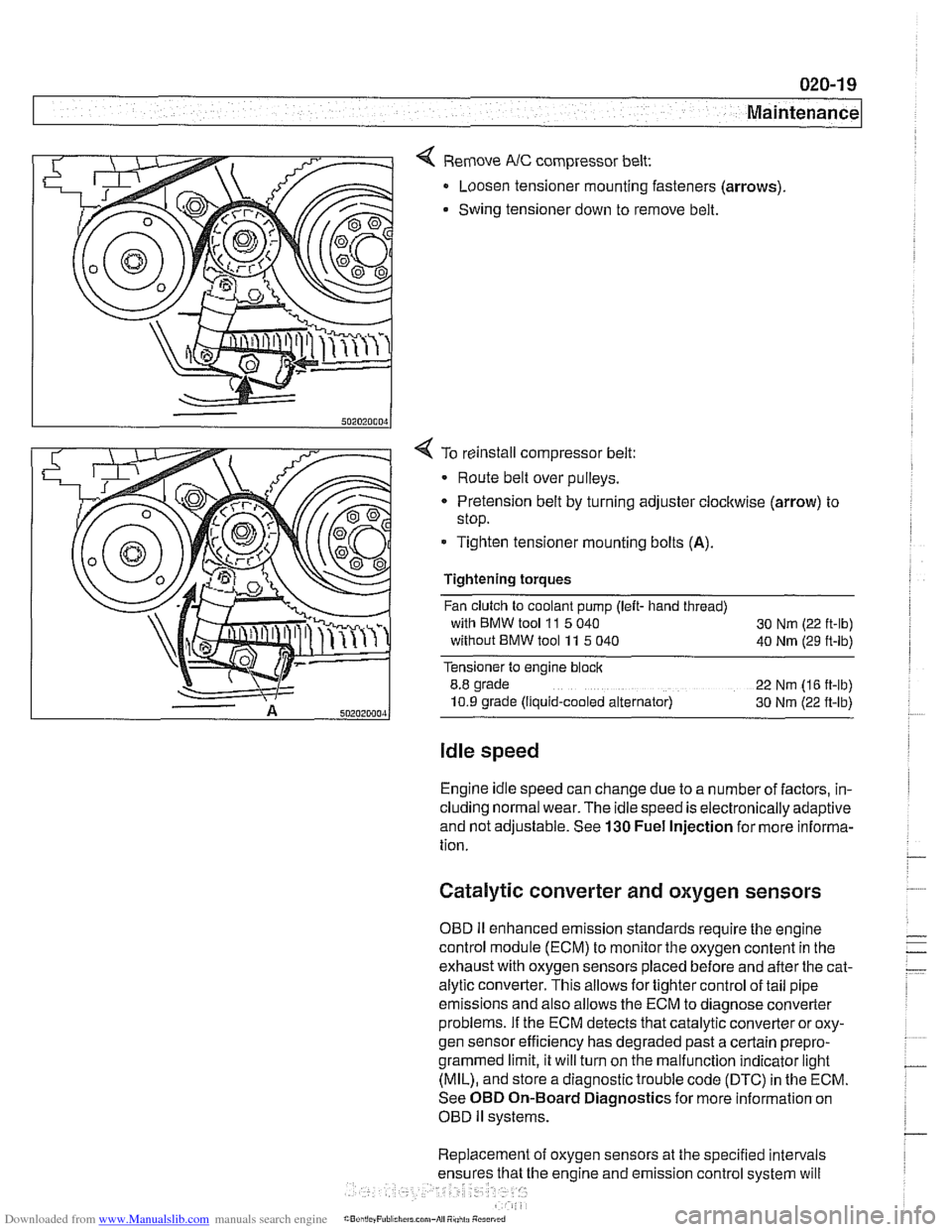
< Remove NC compressor belt:
Loosen tensioner mounting fasteners (arrows)
Swing tensioner down to remove belt.
4 To reinstall compressor belt:
Route belt over pulleys.
* Pretension belt by turning adjuster clockwise (arrow) to
stop.
- Tighten tensioner mounting bolts (A).
Tightening torques
Fan clutch to coolant pump (left- hand thread)
with BMW tool
11 5 040
30 Nm (22 ft-lb)
without BMW tool 11 5 040
40 Nm (29 ft-lb)
Tensioner to engine block
8.8 grade
22 Nm (16 ft-lb)
10.9 grade (Ilquid-cooled alternator) 30 Nm (22 ft-lb)
Idle speed
Engine idle speed can change due to a number of factors, in-
cluding normal wear. The idle speed is electronically adaptive
and not adjustable. See
130 Fuel Injection for more informa-
tion.
Catalytic converter and oxygen sensors
OBD II enhanced emission standards require the engine
control module (ECM) to monitor the oxygen content in the
exhaust with oxygen sensors placed before and after the cat-
alytic converter. This allows for tighter control of tail pipe
emissions and also allows the ECM to diagnose converter
problems. If the ECM detects that catalytic converter or oxy-
gen sensor efficiency has degraded past a certain
prepro-
grammed limit, it will turn on the malfunction indicator light
(MIL), and store a diagnostic trouble code (DTC) in the ECM.
See OBD On-Board Diagnostics for more information on
OBD
ll systems.
Replacement of oxygen sensors at the specified intervals
he engine and emission control system will
Page 97 of 1002

Downloaded from www.Manualslib.com manuals search engine
11 3-3
Cylinder Head Removal and Installation
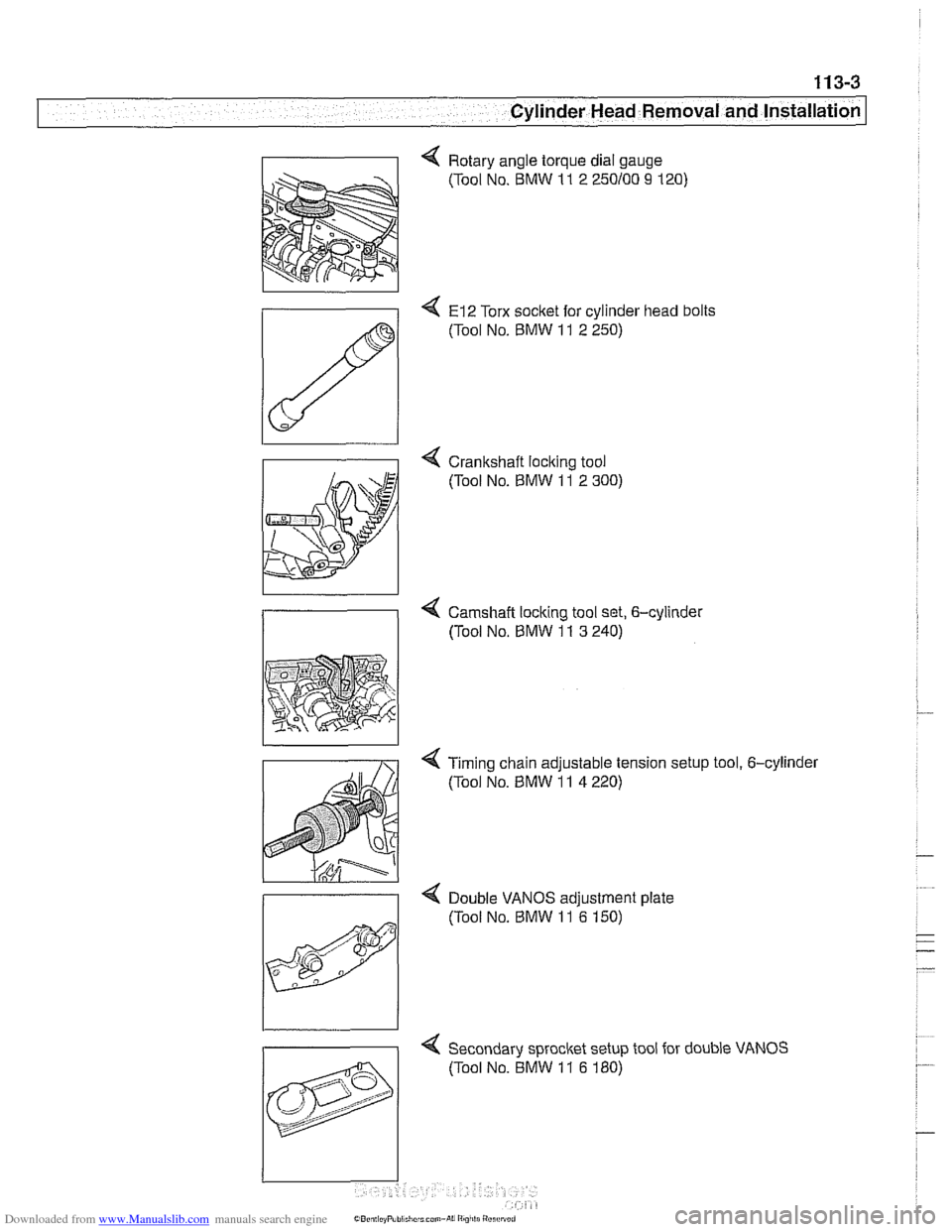
4 Rotary angle torque dial gauge
(Tool No. BMW
11 2 250100 9 120)
4 El2 Torx socket for cylinder head bolts
(Tool No.
BMW 11 2 250)
4 Crankshaft loclting tool
(Tool No.
BMW 11 2 300)
4 Camshaft locking tool set, 6-cylinder
/I (Tool No, BMW 11 3 240)
< Timing chain adjustable tension setup tool, 6-cylinder
(Tool No.
BMW 11 4 220)
>
Double VANOS adiustment date
4 Secondary sprocket setup tool for double VANOS
(Tool No. BMW
11 6 180)
Page 112 of 1002

Downloaded from www.Manualslib.com manuals search engine
I Cylinder Head Removal and Installation
4 Check that two locating dowels are correctly positioned in
block and are not damaged.
- Apply permanently elastic sealing compound Three Bond
1209 8 to joints where cylinder block joins timing case cover.
- Place new cylinder head gasket on cylinder block.
NOTE-
The word "OBEN" or 'TOP': printed on the gasket, should
face up. The cylinder head
gasket will fit correctly in only one
orientation.
- With camshafts locked in TDC oosition with BMW soecial
tools as described during cylinder head removal,
seicylinder
head in position, guiding primary chain through cylinder head
opening.
NOTE-
* The camshafts must be locl(ed in the TDC position at the
rear of the cylinder head with
BMW special tool I1 3 240
before installing the cylinder head.
Make sure the
cranksha% which had been rotated approx-
imately
30" opposite the direction of engine rotation, is still
in that position before lowering the cylinder head into posi-
tion.
- Lightly lubricate new cylinder head bolts. Loosely install bolts
and their washers, then thread them in until they are finger
tight.
NOTE-
. Torx-type cylinder head bolts should not be reused. They
are stretch-type bolts and must always be replaced when-
ever loosened.
Check that all washers for the cylinder head bolts are in
place before installing the bolts. Some of the washers may
be
stalced to the cylinder head.
CAUTIOI\C
Cylinder head bolts for a cast iron engine block are different
length and require different tightening torque than bolts for an
aluminum cylinder bloclc engines
(95 rnm versus 110 rnm
bolts).
- Install cylinder head-to-lower timing chain cover bolts finger
tight.
< Tighten cylinder head bolts in correct sequence to initial
torque value.
Page 113 of 1002

Downloaded from www.Manualslib.com manuals search engine
I Cylinder Head Removal and Installation I
< Use BMW tool 11 2 110 or torque angle gauge to tighten cyl-
inder head bolts in sequence to stage
2 and 3.
Tightening torques
Cylinder head to cast iron
bloclc
Staoe 1
staie 2
Stage 3
Cyllnder head to aiumlnum block
Stage
1 40 Nm (30 it-lb)
Stage 2 +90°
Staoe 3 -80"
- Tighten cylinder head-to-lower timing chain cover bolts.
Tightening torques
cylinderhead to lower timing chain cover 10 Nm (89 in-lb)
- Inspect secondary chain guide rail and tensioner rail for
grooves caused by chain contact. Replace any part that is
worn.
NOTE-
Inspect timing chain sprocl(ets. Sprockets that have worn
or missing teeth should be replaced.
* If any of the sprockets are being replaced due to wear, the
chain should also be replaced.
If the crankshaft sproclet requir?s replacement, the oil
pump drive sprocket and chain must be removed as de-
scribed under
119 Lubrication System.
The procedure outlined below assumes that the camshafts
and the
cranl(shaft are locledin the TDCposition with special
4 Mount primary timing chain sprocltet to primary chain so that
arrow on sprocket faces up. Mount sprocket to camshaft so
that tapped holes in camshaft are on left side of elongated
holes in sprocltet
Install BMW special tool
1 I 4 220 into primary timing chain
tensioner sleeve. Thread center spindle in finger tight
until
slack is removed from chain.
Page 114 of 1002

Downloaded from www.Manualslib.com manuals search engine
--
Cylinder Head Removal and Installation
NOTE-
BMW special tool 11 4 220 is an adjustable primary chain
tensioner and simulates the function of the hydraulic
tensioner.
- Check that elongated holes in primary sprocket are now cen-
tered to bolt holes in camshaft and chain is free of slack. If
not, reposition sprocket to chain and reinstall.
- lnstall secondary timing chain guide and secondary chain
tensioner. Tighten mounting bolts (tensioner remains locked
down for now using
BMW special tool 11 3 292).
- Install cylinder identification trigger plate to front of intake
camshaft with studs.
- Install spacer to front of intake camshaft.
- Install secondary chain sprockets and chain as an assembly
so that arrows on sprockets are pointing up. Center mounting
holes in sprockets to bolt holes in camshafts.
4 lnstall thrust washers and diaphragm spring to intake cam
sprocket.
I 2hm thrust washer I
- Install shim and torx bolts to exhaust camshaft. Tighten fin-
ger tight; do not torque down.
- Tighten intake sprocket nuts.
CA UTIOG
Hold the camshaft stationary (at hex on camshaft) when loos-
enino or tiahtenino sorocket mounting bolts and studs.
Tightening torque
Intake s~rocket nuts to studs 10 +l Nm (89 +9 in-lb)
- Turn crankshaft approx. 30" in direction of rotation to bring
engine to TDC. Lock crankshaft in TDC position with BMW
special tool
11 2 300.
CAUTION-
The camshafts andcranlshaft must be lockedin the TDCpo-
sition using BMW special tools 11 2 300 and 11 3 240. If the
camshafts and cranl(shaft are not at TDC, the valves can
contact the pistons.