2000 BMW 540i Release
[x] Cancel search: ReleasePage 505 of 1002

Downloaded from www.Manualslib.com manuals search engine
Radiator and Cooling System
Check for cloggedlplugged radiator or coolant passages.
Cooling system pressure test
A cooling system pressure tester is used to test for coolant
leaks, including internal ones. Common sources of internal
coolant leaks are a faulty cylinder head gasket, a
craclted cyl-
inder head, or a cracked engine block.
WARNING-
At normal operating temperature the cooling system is pres-
surized. Allow the system to cool before opening. Release
the cap slowly to allow safe release ofpressure.
4 With engine cold, install pressure tester (BMW special tools
17 0 002117 0 005 or equivalent) to expansion tank. Pressur-
ize system to specification listed in Table a. Cooling system
test pressures.
Pressure should not drop more than 0.1 bar (1.45 psi) for
at least two minutes.
. If pressure drops rapidly and there is no sign of external
leakage, cylinder head gasket may be faulty. Perform com-
pression and leak-down tests.
Test expansion
tank cap using pressure tester with correct
adapter (BMW special tool 17
0 007 or equivalent). Re-
place faulty cap or cap gasket.
Table a. Cooling system test pressures
0021663 I Component l~est pressure
Radiator
11.5 bar (21.75 psi)
Radiator cap
12 bar (29 psi)
CAUTION-
Exceeding the specified test pressure could damage the ra-
diator or other svstem
com~onents.
Page 530 of 1002

Downloaded from www.Manualslib.com manuals search engine
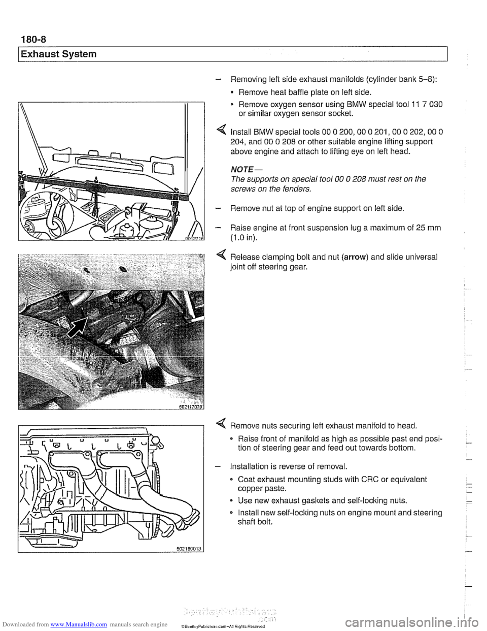
- Removing left side exhaust manifolds (cylinder bank 5-8):
- Remove heat baffle plate on left side.
Remove oxygen sensor using
BMW special tool 11 7 030
or similar oxygen sensor socket.
Install
BMW special tools 00 0 200,OO 0 201,OO 0 202,OO 0
204, and 00 0 208 or other suitable engine lifting support
above engine and attach to lifting eye on left head.
NOTE-
The supports on special tool 00 0 208 must rest on the
screws on the fenders.
- Remove nut at top of engine support on left side
- Raise engine at front suspension lug a maximum of 25 mm
(I
.O in).
Release clamping bolt and nut
(arrow) and slide universal
joint off steering gear.
4 Remove nuts securing left exhaust manifold to head,
Raise front of manifold as high as possible past end posi-
tion of steering gear and feed out towards bottom.
- Installation is reverse of removal.
Coat exhaust mounting studs with CRC or equivalent
copper paste.
Use new exhaust gaskets and self-locking nuts.
Install new self-locking nuts on engine mount and steering
shaft bolt.
Page 546 of 1002

Downloaded from www.Manualslib.com manuals search engine
Tool for bleeding clutch hydraulics (Tool No. 21 5 030)
21 5 030 I
The clutch is hydraulically actuated by the master and slave
cylinders. With the self-adjusting clutch
(SAC), clutch disc
wear is automatically taken up through the self-adjusting
pressure plate springs, making pedal feel consistent through-
out the life of the clutch.
A soft or spongy feel to the clutch pedal, long pedal free-play,
or grinding noises
from the gears while shifting can all indi-
cate problems with the clutch hydraulics. In these circum-
stances it is best to
star? with a clutch fluid flush, followed, if
necessary, by replacement of the hydraulic parts.
NOTE-
The clutch hydraulic system shares the fluid reservoir and flu-
id with the brake hydraulic system.
Clutch hydraulic system,
bleeding and flushing
If the clutchlbralte fluid is murky or muddy, or has not been
changed within the last two years, flush the system and
change the fluid. Flushing the old fluid from the clutch lines is
done using a bralte system pressure bleeder.
- Remove brake fluid reservoir cap. Using a clean syringe, re-
move brake fluid from reservoir. Refill reservoir with clean
DOT
4 bralte fluid.
Worlting inside engine compartment, remove left
interiorven-
tilation filter housing:
Release 3 plastic taps
(A) on duct. Earlier models use a
single release latch.
Rotate duct inward to remove.
Disconnect electrical harness to hood position switch.
Remove filter housing cover.
Release spring lock
(B) on interior ventilation housing and
remove housing.
Page 548 of 1002

Downloaded from www.Manualslib.com manuals search engine
21 0-6
1 Clutch
Hydraulic system, bleeding
(using
BMW special tool 21 5 030)
4 Working underneath transmission, remove slave cylinder
mounting nuts (arrow) from clutch housing and remove
cylinder. Leave fluid line attached.
4 Use BMW special tool 21 5 030 to press slave cylinder push-
rod completely into slave cylinder.
Hold slave cylinder so that bleeder valve is at highest point.
Open bleeder valve and allow brake fluid to expel until
clean fluid comes out, free of air bubbles.
* Close bleeder valve and disconnect pressure bleeding
equipment from fluid reservoir.
Slowly unscrew and detach special tool 21
5 030 from
slave cylinder.
CAUTION-
Do not remove tool if hydraulic system is pressurized.
- Reinstall slave cylinder.
Tightening torque Slave cylinder to transmission case
22 Nm (1 6 ft-lb)
- Slowly operate clutch pedal about 10 times. Fill reservoir with
clean fluid as necessary.
Clutch master cylinder, replacing
The clutch master cylinder is mounted to the pedal assembly
directly above the clutch pedal.
Working inside engine compartment, remove left interior
ventilation filter housing:
Release 3 plastic taps
(A) on duct. Earlier models use a
single release latch.
Rotate duct inward to remove
Disconnect electrical harness to hood position switch.
Remove filter housing cover.
Release spring
loclc (B) on interior ventilation housing and
remove housing.
Page 550 of 1002

Downloaded from www.Manualslib.com manuals search engine
21 0-8
Clutch
4 Remove hydraulic line locking clip (1) and pull line (2) off
master cylinder.
CAUTION-
. To prevent brake fluidspill, wrap clutch master cylinder with
shop rags when removing hydraulic fluid lines from master
cylinder.
* Brake fluid damages paint andstains carpets. Clean off
any brake fluid on or
in the car immediately.
- Remove master cylinder with supply hose
4 Remove switch module from master cylinder.
Press locking button
(A) to release harness connector.
Pull harness connector
(8) off switch module.
Use screwdriver to lever
off switch module (C).
- Installation is reverse of removal.
CA UTlON-
Switch module must snap firmly into place on the master cyl-
inder during installation.
Tightening torques
Clutch master cylinder to pedal cluster
10 Nm (89 in-lb)
Fluid line
to master cylinder or slave cylinder 17 Nm (13 ft-lb)
- Fill fluid reservoir with clean fluid. Bleed clutch hydraulics as
described earlier.
Clutch slave cylinder, replacing
4 Working inside engine compartment, remove left interiorven-
tilation filter housing:
Release
3 plastic taps (A) on duct. Early models: release
latch.
Rotate duct inward to remove.
Disconnect electrical harness to hood position switch.
Release spring lock (B) on interior ventilation housing and
remove housing.
- Pinch off brake fluid supply hose to clutch master cylinder us-
ing BMW special tool
13 3 01 0 or equivalent hose clamping
tool.
Page 551 of 1002

Downloaded from www.Manualslib.com manuals search engine
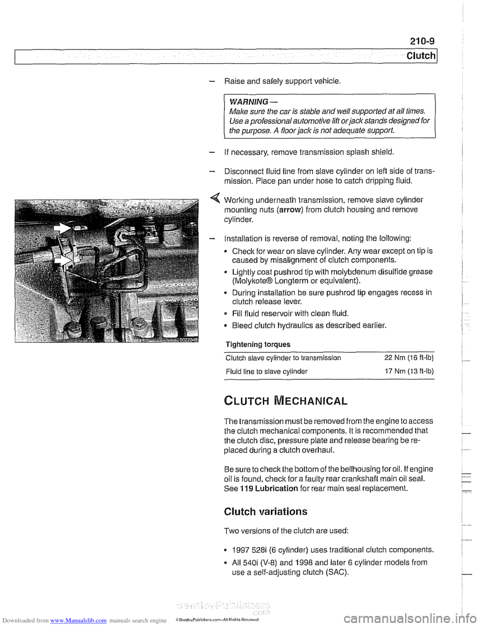
- Raise and safely support vehicle
WARNING-
Make sure the car is stable and well supporied at all times.
Use a professional automotive /iff orjack stands designed for
the
ournose. A floor jack is not adeouate suooort.
- If necessary, remove transmission splash shield.
- Disconnect fluid line from slave cylinder on lefl side of trans-
mission. Place pan under hose to catch dripping fluid.
4 Working underneath transmission, remove slave cylinder
mounting nuts (arrow) from clutch housing and remove
cylinder.
- Installation is reverse of removal, noting the following:
Check for wear on slave cylinder. Any wear except on tip is
caused by misalignment of clutch components.
Lightly coat
pushrod tip with molybdenum disulfide grease
(MolyltoteIB Longterm or equivalent).
. During installation be sure pushrod tip engages recess in
clutch release lever.
Fill fluid reservoir with clean fluid.
. Bleed clutch hydraulics as described earlier.
Tightening
toraues - -.
Clutch slave cylinder to transmission 22 Nm (16 R-lb)
Fluid line to slave cylinder 17 Nm (13 ft-lb)
The transmission must be removed from the engine to access
the clutch mechanical components. It is recommended that
the clutch disc, pressure plate and release bearing be re-
placed during a clutch overhaul.
Besure tocheck the bottom of the bellhousing foroil. If engine
oil is found, check for a faulty rear crankshaft main oil seal.
See
119 Lubrication for rear main seal replacement.
Clutch variations
Two versions of the clutch are used:
1997 528i (6 cylinder) uses traditional clutch components.
All
540i (V-8) and 1998 and later 6 cylinder models from
use a self-adjusting clutch (SAC).
Page 553 of 1002

Downloaded from www.Manualslib.com manuals search engine
Clutch, removing
The procedure given here applies to both non-SAC and SAC
clutch assemblies.
- Remove transmission from engine. See 230 Manual Trans-
mission.
4 Loosen 6 clutch mounting bolts (arrows) evenly
- Remove pressure plate and clutch disc.
WARNING-
The clutch disc contains asbestos. Inhaling or ingesting as-
bestos dust can cause severe health problems. Always wear
an approved respiratorandprotective clothing when handling
components containing asbestos. Do not use compressed
air to clean components. Do not
grind, heat, weld, or sand on
or near anv asbestos materials.
Pull release bearing off transmission input shaft. Remove
clutch release lever by sliding it out of spring clip in direction
of arrow.
Clutch components, inspecting
- Inspect clutch disc for wear, cracks, loose rivets, contamina-
tion or excessive
runout (warping). Replace if necessary.
- Measure clutch disc lining thickness at shallowest rivet head. 7
Clutch and pressure plate wear limits
Minimum clutch disc lining thickness (at rivets)
1.0
mm (0.04 in) - Maxtmum lateral runout
(d~aphragm sprtngs to pressure plate) 0 6 mm (0 02 in)
Page 554 of 1002

Downloaded from www.Manualslib.com manuals search engine
21 0-1 2
Clutch
Release bearing
Release
bearin
- lnspect flywheel for scoring, hot spots, cracks or loose or
worn guide pins. If any faults are found, replace flywheel as
described later.
- lnspect transmission pilot bearing in end of crankshaft. The
bearing should rotate smoothly without play. If necessary,
replace as described later.
4 lnspect and clean release bearing lever. Apply a thin coat of
grease to release bearing lever lubrication points (arrows).
Clean and lightly lubricate clutch disc splines and transmis-
sion input
shaft splines.
4 Checlc release bearing ball stud and spring retainer. Replace
if damaged or worn.
CAUTION--
On S6S 420G transmission, always replace release bearing
ball stud and retainer spring.
- Clean release bearing guide sleeve.
CA U TIOG
Do not grease guide sleeve. If guide sleeve is greased,
release bearing may stick to it.
Flywheel, removing and installing
(6 cylinder engine)
- lnspect flywheel for scoring, hot spots, cracks or loose or
worn guide pins. Replace flywheel if any faults are found.
Lock flywheel with BMW special tool
11 2 170. Remove
pressure plate and clutch disc as described earlier.
- Loosen and remove flywheel mounting bolts. Remove
flywheel.
- Clean flywheel bolt threads in crankshaft.