Page 192 of 1002

Downloaded from www.Manualslib.com manuals search engine
.
Cylinder Head and Valvetrain
< Remove cylinder head cover retaining studs (arrows) from
center and rear of cylinder head.
< Remove spark plugs and install BMW special tool 11 3 260
(A) and 11 3 270 (6) to cylinder head. Tighten tool retaining
bolts in spark plug bores. Do not overtighten bolts.
Tightening
torque
BMW special tool 11 3 260 I1 1 3 270 to 23 Nm (17 It-lb)
cylinder head
- Remove intake camshaft bearing cap for cylinder number 1.
CA UTIOG
Intake camshaft bearing cap 1 is centered with adapter
sleeves. To avoid
can~sllaft daniage, it must be removed bs-
fore any other caps.
Turn eccentric shaft on special tool until pressure is applied
to camshaft bearing caps.
- Remove remaining bearing cap mounting nuts
- Slowly release pressure on camshaft bearing caps by turning
eccentric shaft. Remove bearing caps and camshaft. Repeat
procedure on remaining camshaft.
CAUTION-
Camshaft bearing caps must be reinstalled in their original lo-
cations.
NOTE-
The camshaft bearing caps are coded with a letter anda
number. For example,
'XI" is the first exhaust camshaft
bearing cap at the front of the engine, and
"El "is the intalce
camshaft bearing cap at the front of the engine.
0 The camshafts are stamped with a code letter - "E" for the
intake side and 'MA" for the exhaust side.
0 "E is for Einlap, (German for intake) and 'XA"is for Auspuff,
(German for exhaust).
Page 200 of 1002

Downloaded from www.Manualslib.com manuals search engine
..--.
I Cylinder Head and Valvetrain - I
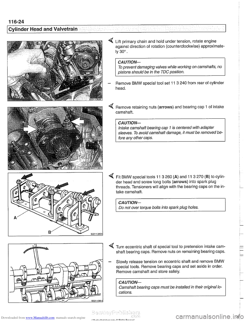
4 Lift primary chain and hold under tension, rotate engine
against direction of rotation (counterclockwise) approximate-
ly 30".
To prevent damaging valves while
worlcing on camshafts, no
aistons should be in the TDC position.
- Remove BMW special tool set 1 I 3 240 from rear of cylinder
head.
Remove retaining nuts (arrows) and bearing cap
1 of intake
camshaft.
Intake camshaft bearing cap
1 is centered with adapter
sleeves. To avoid camshaft damage, it must be removed be-
fore anv other caos.
4 Fit BMW special tools 11 3 260 (A) and 11 3 270 (B) to cylin-
der head and screw long bolts (aiiows) into spark plug
threads. Tensioners will align with the bearing caps on the in-
take camshaft.
CA UTION--
Do not over torque bolts into spark plug holes. 1
4 Turn eccentric shaft of special tool to pretension intake carn-
shaft bearing caps. Remove nuts on remaining bearing caps.
- Slowly release tension on eccentric shaft and remove BMW
special tools. Remove bearing caps and set aside in order.
Remove camshaft and store safely.
CA U TIOW-
Camshaft bearing caps must be installed in their original lo-
cations.
Page 203 of 1002

Downloaded from www.Manualslib.com manuals search engine
-- - . .- -,
Cylinder Head and Valvetrain
4 Rotate camshafts so that intalte and exhaust lobes for cylin-
der
1 face each other (arrows).
CAUJION-
A minimum waiting time is required for the hydraulic lifters to
'bleed down"after installing the camshafts into the cylinder
head, before bringing the piston to TDC. When the camshafts
are removed, the hydraulic lifters can expand. This expan-
sion can cause increased valve lift when the camshafts are
bolted down, possibly resulting in piston interference.
Place bearing caps on cams, but do not install retaining nuts.
4 Fit BMW special tool 11 3 260 (A) and 11 3 270 (B) to cylinder
head over
intalte camshaft and screw long bolts (arrows)
into spark plug threads.
CA UTION-
Do not overtighten bolts into spark plug holes.
< Turn eccentric shaft of special tool to pretension bearing
caps. Install and torque nuts on intake camshaft bearing
caps.
Tightening torque Camshaft bearing cap
to cylinder head (M7) 14 Nm (10 it-ib)
- Release tension on eccentric shaft and remove BMW special
tools
11 3 2601270.
- Repeat procedure for exhaust camshaft.
NOTE-
Observe waiting time for lifter bleed down before continuing
with camshaff installation.
Crankshaft
I valve timing waiting times
68°F (20°C) and higher 5 minutes
50-6S°F(10-20°C) 15 minutes
32-50DF(O-10°C) 30 minutes
Page 215 of 1002

Downloaded from www.Manualslib.com manuals search engine
Cylinder Head and valvetrain1
Camshaft removal and installation
(M62 engine)
Camshafts, removing (M62 engine)
Special
BMW service tools should always be used to remove
and install the camshafts. Removal of the camshafts without
the special tools can result in personal injury and lor cylinder
head damage.
NOTE-
Cylinder bank 1-4 is referred to as the right cylinder bank
and is located on the passenger side. Cylinder bank 5-8 is
referred to as the left cylinder bank and is located on the driv-
er's side.
WARNING-
Allow enqine to cool before beqinninq this procedure. 1
- Disconnect negative (-) cable from battery.
CAUTION-
Prior to disconnecting the battery, read the battery discon-
nection cautions
in 001 General Cautions and Warnings.
- Dra~n coolant. See 170 Radiator and Cooling System.
Remove plastic engine covers:
Press down on locking pins (arrows) and remove top
cover.
Pry out
trlm caps (A) from covers.
Remove fasteners from beneath
trlm caps and remove
side covers.
4 Remove left and right interior ventilation filter housing (lefl
side shown):
Release locking tabs
(A) or locking strap (early models,
not shown).
Rotate duct inward (arrow) to disconnect.
- Release spring lock (6) to unloclc ventilation housing.
Disconnect electrical harness from hood switch
(C).
Release locking clip and remove ventilation filter cover (0).
Remove filter housing.
Removal of right side ventilation duct is similar.
Page 268 of 1002

Downloaded from www.Manualslib.com manuals search engine
-- -
Chain 1
- Install cylinder identification trigger plate to front of intake
camshaft.
- Install spacer to front of intake camshaft
- Install secondary chain sprockets and chain as an assembly
so that arrows on sprockets are pointing up. Center mounting
holes in sprockets to bolt holes in camshafts.
4 lnstall thrust washers and spring plate to intake cam
sprocket.
Tighten intake camshaft sprocket nuts.
- Install VANOS control unit, see VANOS control unit, install-
ing
(M52 engine).
Tightening torque
Intake camshaft sprocket nuts to studs
(ME) 1011 Nm (8919 In-lb) 502117068
- Unlock and release secondary chain tensioner,
4 Preload primary timing chain by torquing adjustable primary
chain tensioner (BMW special tool
11 4 220) to 1.3 Nm
(11 in-lb).
- Tighten exhaust camshaft sprocket bolts in two stage
Tightening torque Exhaust camshaft sprocket bolls (M7)
Stage 1
5 Nrn (44 in-lb)
Stage
2 22 Nm (17 ft-lb)
- Remove crankshaft locking tool and camshaft locking tools.
< Align hub with keyway and tap into place. Insert new center
bolt with washer shoulder (arrow) facing hub.
CAUTION-
Inspect woodruff ley for damage before installing hub.
- Attach crankshaft holding tool (BMW special tools 11 2
15011 1 2 410) to hub. Counterhold hub with tool while tight-
ening center bolt.
CAUTION-
Do not use flywheel locling tool to hold crankshaft stationary
to loosen or tighten
cranlshaft hub center bolt. Use only the
special tools specified, or equivalent hub holding tool.
Page 282 of 1002
Downloaded from www.Manualslib.com manuals search engine
1 17-46
Camshaft Timing Chain
4 Loosen intake camshaft sprocket mounting nuts (arrows) by
1 turn.
Loosen exhaust camshaft sprocltet mounting bolts:
Release bolts
(A) 112 turn
Release nuts
(B) 2 turns
Pull out intake camshaft splined shaft out approx.
1 mm
(0.04 in) of splines (arrows) can be seen.
Page 303 of 1002

Downloaded from www.Manualslib.com manuals search engine
Camshaft Timing chain1
- Disconnect negative cable (-) from battery.
CAUTION-
Prior to disconnecting the battery, read the battery discon-
nection cautions given
in 001 General Cautions and
Warnings.
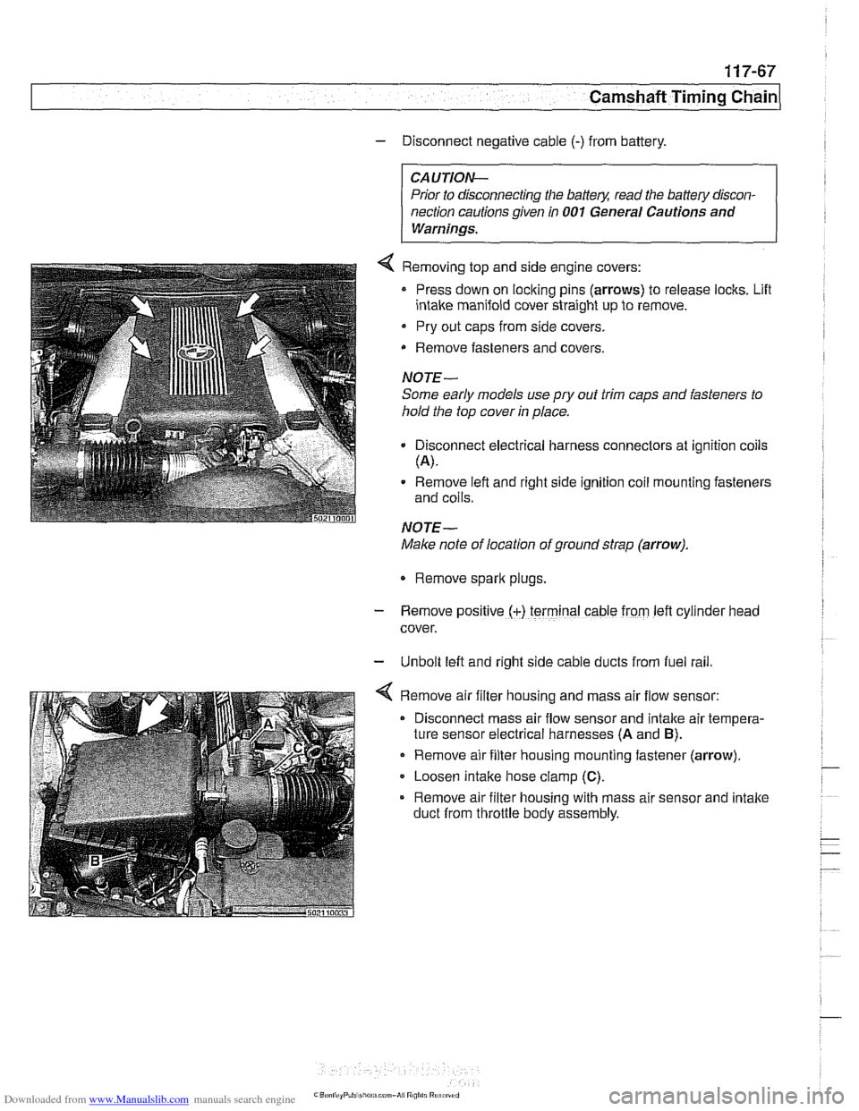
4 Removing top and side engine covers:
Press down on locking pins (arrows) to release locks. Lifl
intake manifold cover straight up to remove.
Pry out caps from side covers.
Remove fasteners
and covers.
NOTE-
Some early models use
pry out trim caps and fasteners to
hold the top cover in place.
Disconnect electrical harness connectors at ignition coils
(A).
Remove left and right side ignition coil mounting fasteners
and coils.
NOTE-
Make note of location of ground strap (arrow).
Remove spark plugs.
- Remove posltlve (+) terminal cable from left cylrnder head
cover.
- Unbolt left and right side cable ducts from fuel rail
Remove air filter housing and mass air flow sensor:
Disconnect mass air flow sensor and intake air tempera-
ture sensor electrical harnesses
(A and B).
Remove air filter housing mounting fastener (arrow)
Loosen intake hose clamp
(C).
Remove air filter housing with mass air sensor and intake
duct from throttle body assembly.
Page 304 of 1002
Downloaded from www.Manualslib.com manuals search engine
1 17-68
Camshaft Timing Chain
4 Remove left and right side ignition coils and spark plugs:
- Remove positive (+) terminal cable from left cylinder head
cover.
- Unbolt lefl and right side cable ducts from fuel rail,
4 Disconnect fuel injector electrical connectors:
Pry corner of wire lock clip to release connector from injec-
tor
(arrow).
Repeat for all injectors.
Lift off wiring ducts.
4 Remove Fasteners (arrow) from lefl and right cylinder head
cover fasteners and remove covers.