2000 BMW 540i Wire plugs
[x] Cancel search: Wire plugsPage 52 of 1002

Downloaded from www.Manualslib.com manuals search engine
Maintenance
continue to operate as designed. Extending the replacement
interval may void the emission control warranty coverage.
See
180 Exhaust System for information on replacing the
oxygen sensors.
Tightening torque
Oxvoen sensor to exhaust
manifold 50 Nrn (37 ft-lb)
NOTE-
A special soclet for replacing the oxygen sensor is available
from most automotive parts stores. The soclet has
a groove
cut down one side to allow the sensor to be installed without
damaging the wire harness.
Power steering fluid, checking level
The power steering system is permanently filled and does not
have a drain. Routinely adding ATF is not required unless the
system is leaking.
4 To check power steering fluid level in fluid reservoir:
Park car on level ground with engine off.
Level is correct
if it is between MlN and MAX marks on
dipstick.
If level is below
MlN mark, add fluid to reservoir to bring
level up.
* Hand-tighten reservoir cap.
Power steering fluid
Dexron
1iiO ATF or equivalent
Spark plugs
E39 models through model year 1998 were equipped with
spark plugs with two electrodes. These are gapped to
0.7 mm
(0.028 in) by the manufacturer and are not adjustable.
Starting with 1999 models, long life spark plugs with
3 or four
electrodes were used. These can be retroactively fitted to
earlier
models. The recommended spark plug replacement
interval
forthese is 100,000 miles.The electrode gap in these
spark plugs is not adjustable.
Spark plug applications
M52 Bosch FBLDCR
M52 TU, M54 Bosch FGR7DQP or NGK BKRBEQUP
M62 to 7/97 Bosch F7LDCR or NGK BKR6EK
M62 from 7/97 Bosch F9LDCR
M62 TU Bosch FGR7DQP or NGK BKRGEQUP
Page 54 of 1002

Downloaded from www.Manualslib.com manuals search engine
020-22 Maintenance
1
- Installation is reverse of removal, bearing in mind the
following:
Lightly lubricate new
spark plug threads with
copper-based anti-seize compound.
Thread plugs into cylinder head by hand to prevent
cross-threading.
. Be sure to reinstall and tighten coil grounds.
Tightening torque Spark plug
to cylinder head 25 Nm (18 It-lb)
Interior ventilation microfilter, replacing
Two interior ventilation microfilters are used, one on each
side of the engine compartment at the fire wall.
< To replace the microfilter, unclip the wire fastener and
remove the cover.
Lift out the filter, and replace. Left side shown; right is
similar.
Replace cover and clip wire fastener to retain cover.
Battery, checking, cleaning, and replacing
The battery Is located in the right side of the luggage compart-
ment. Simple maintenance of the battery and its terminal
connections will ensure maximum starting periormance,
especially in winter when colder temperatures reduce battery
power.
Battery cables should be tight. The terminals, cable clamps
and battery case should be free of the white deposits that
indicate corrosion and acid salts. Even a thin layer of dust
containing conductive acid salts can cause battery discharge.
Page 75 of 1002

Downloaded from www.Manualslib.com manuals search engine
110-3
Engine Removal and lnstallationl
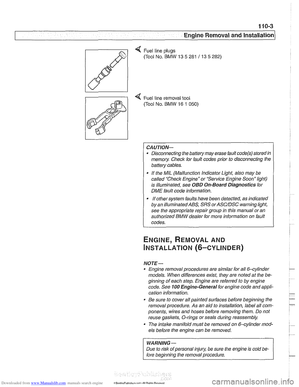
Q Fuel line plugs
(Tool No.
BMW 13 5 281 / 13 5 282)
4 Fuel line removal tool
(Tool No.
BMW 16 1 050)
CAUTION-
Disconnecting the battery may erase fault code@) storedin
memoiy Check for fault codes prior to disconnecting the
battery cables.
If the MIL (Malfunction Indicator Light, also may be
called "Check Engine" or "Service Engine Soon" light)
is illuminated, see
OBD On-Board Diagnostics for
DME fault code information.
It orhersysrem faults have been detected, as indicated I
by an ~llum~nated ABS, SRS orASC/DSC ~arning light,
see the appropriate repair group in this manual or an
authorized BMW dealer for more information on fault
codes.
NOTE- Engine removal procedures are similar for all 6-cylinder
models. When differences
exist, they are noted at the be-
ginning of each step. Engine are referred to by engine
code. See
100 Engine-General for engine code and appli-
cation information.
@ Be sure to cover all painted surfaces before beginning the
removal procedure. As an aid to installation, label all com-
ponents, wires and hoses before removing them. Do not
reuse
gaskets, O-rings or seals during reassembly.
The
intake manifold must be removed on &cylinder mod-
els before the engine can be removed.
WARNING-
Due to risk of personal injury, be sure the engine is cold be-
fore beginning the removal procedure.
Page 101 of 1002

Downloaded from www.Manualslib.com manuals search engine
. .- . --
Lr -- - - - -- Cylinder Head Removal and Installation I -
- Release pressure at compression gauge valve, then remove
gauge from spark plug hole. Repeat test for each cylinder
and compare results with values given in Table a.
Table a. Compression testing specifications
Minimum compression
6-cylinder
10-1 1 bar (142-156 psi)
V-8 12-14 bar (174-203 psi)
Maximum difference between
cylinders (all engines)
0.5 bar (7 psi)
- Compression readings may be interpreted as follows:
Low compression indicates a poorly sealed combustion
chamber.
0 Relatively even pressures that are below specification nor-
mally indicate worn piston rings
andlor cylinder walls.
Erratic values tend to indicate valve leakage.
Dramatic differences between cylinders are often a sign of
a failed head
gasket, burned valve, or broken piston ring.
- If readings are within specifications, reinstall spark plugs and
ignition coils.
NOTE-
Used spark plugs should be reinstalled in the same cylinder
from which they were removed.
Tightening torque Spark plug to cylinder head 25 Nm
(18 ft-lb)
lanition coils to cylinder head 10 Nm (7.5 ft-lb)
- Remainder of installation is reverse of removal. Be sure to re-
install all wires disconnected during test, especially ground
wires at coils and cylinder head cover (where applicable).
Wet compression test
To further help analyze the source of poorcompression,awet
compression test is the next step.
- Repeat compression test, this time squirt a teaspoon of oil
into each cylinder. The oil will temporarily help seal between
piston rings and cylinder wall, practically eliminating leakage
past rings for a short time.
- If this test yields a higher reading than "dry" compression
test, there is probably leakage between piston rings and
cylinder walls, due either to wear or to broken piston rings.
- Little or no change in compression reading indicates other
leakage, probably from valves.
Page 106 of 1002

Downloaded from www.Manualslib.com manuals search engine
-
Cylinder Head Removal and Installation c
q Remove secondary air inject~on check valve (arrow).
4 Remove cylinder head top cover:
Remove plastic trim caps (arrows).
Remove engine oil filler cap.
Remove cover hold down fasteners and lift off cover.
4 Remove ignition coils:
Disconnect ignition coil harness connectors.
. Remove coil mounting fasteners.
Remove coils.
Remove ground straps.
NOTE-
Make note of ground wire at mounting studs arrangement
during removal.
- Remove sparlc plugs.
- Remove cylinder head cover mounting fasteners and remove
cylinder head cover.
NOTE-
The cylinder head cover mounting bolt insulators and gas-
lets should be reinstalled in their original locations. Make
note of their arrangement during removal.
Page 123 of 1002

Downloaded from www.Manualslib.com manuals search engine
Cylinder Head Removal and Installation
4 If applicable, remove secondary air injection pump:
Disconnect hose at one-way valve
(A).
Remove bolts at support bracket on strut tower (arrows).
Disconnect electrical harness from bottom of secondary
air injection pump.
Remove mounting bracket from strut tower.
4 Remove ignition coils:
* Disconnect ignition coil harness connectors.
Remove coil mounting fasteners.
Remove coils.
* Remove ground straps.
CA UTIOI\C
Note location of all ground wires. Failure to reinstall grounds
can result in permanent damage to engine control module or
ignition system components.
Set coil harness to side of engine compartment
- Remove cylinder head cover mounting fasteners and remove
cylinder head cover.
NOTE-
The cylinder head cover mounting bolt insulators and gas-
ltets should be reinstalled in their original locations. Male
note of their arrangement during removal.
- Remove spark plugs
4 Remove oil baffle cover from above intake camshaft.
Page 166 of 1002

Downloaded from www.Manualslib.com manuals search engine
/Cylinder Head Removal and Installation
- Remainder of installation is reverse of removal, noting the fol-
lowing:
Use new gaskets when mounting intake
manifold. Tighten
nuts finger tight first, then torque to specification in stages
working diagonally from center out.
Be sure to reinstall ignition coil ground straps at cylinders
no.
3 and no. 7. See 120 Ignition System.
Reinstall cooling fan and shroud. See
170 Radiator and
Cooling System.
Refill and bleed cooling system as described in
170 Radi-
ator and Cooling System.
Change engine oil and filter as described in
020 Mainte-
nance.
CA UTIOG
To prevent damaging engine electricalsystems, be sure to in-
stall all ground wires previously removed.
Tightening torques
Camshaft sprocket to camshaft 15
Nm (11 H-lb)
Coolant manifold to cylinder head 10 Nm (7.5 H-lb)
Cylinder head cover nuts 10 Nm (7.5 ft-lb)
Exhaust manifold to head 22 Nm (17 ft-lb)
Engine mounts to subirame 42 Nm (30 ft-lb)
Spark plugs to cylinder head 22 Nm (17 ft-lb)
Right cylinder head, removing, M62 engine
- Remove left side exhaust manifold. See 180 Exhaust Sys-
tem.
- Remove intake manifold. See Intake manifold, removal
and installation,
M62 engine.
- Drain engine coolant. See 170 Radiator and Cooling Sys-
tem.
WARNING-
Use extreme caution when draining and disposing of engine
coolant.
Coolanl is poisonous andlellial lo liumans andpels.
Pets are
altracled to coolant because of 11s sfieet smell and
fasle. Seelc medcal anenfion immed~alely if coolant is ingesl-
. .-
< Remove engine coolant manlold mo~nlng fasreners and
carei~lly remove manifo d.
. I
NOTE
Engine 8s slioivn removed lor clarify
Page 176 of 1002

Downloaded from www.Manualslib.com manuals search engine
1 13-82
1 Cylinder Head Removal and Installation
4 Reinstall cylinder head covers to right and left cylinder heads
using new gaskets.
Check for correct seating of half-moon seals
(A) in back of
cylinder head cover.
Use a small amount of Three Bond
1209 8 or equivalent
sealer at corners
(B) of half-moon cutouts.
- Install cylinder head cover fasteners and tighten uniformly in
'I2 turn steps.
Tightening torque Cvlinder head cover fasteners
10 Nm (7.5 It-lb)
- Install exhaust manifolds using new gaskets and fasteners.
See
180 Exhaust System.
- Refill and bleed cooling system as described in 170 Radiator
and Cooling System.
- Change engine oil and filter as described in 020 Mainte.
nance.
CA UTIOW-
To prevent damaging engine electricalsystems, be sure to in-
stall all ground wires previously removed.
Tightening
tOrqUeS
Camshaft sprocket to camshaft 15 Nm (1 1 ft-lb)
Coolant manifold to cylinder head lo Nm (7.5 It-lb)
Cylinder head cover nuts 10 Nm (7.5 ft-lb)
Exhaust manifold to head 22 Nm (17 ft-lb)
Engine mount to subframe 42 Nm (30 ft-lb)
Spark plugs to cylinder head 22 Nm (17 ft-lb)