2000 BMW 530i battery
[x] Cancel search: batteryPage 287 of 1002

Downloaded from www.Manualslib.com manuals search engine
... -.
Camshaft Timing chain1
Timing chains, removing
(M52 TU and M54 engines)
Camshaft timing chain removal requires that the oil pan be re-
moved. See
119 Lubrication System. Also required is re-
moval of the VANOS control
unit and disassembly of the
intake and exhaust camshaft sprocket assemblies as de-
scribed earlier in this repair group.
Special BMW
service tools are needed for timing chain re-
moval and installation. The special tools assure proper timing
of the valvetrain. Precise
marlts to set the timing on the cam:
shafts are not provided for reassembly. Read the procedures
through before beginning the job.
CA
UTION-
If the camshafts are not properly timed, the pistons can con-
tact the valves.
- D~sconnect negative (-) cable from battery.
CAUTION-
* Disconnecting the battery may erase fault code@) stored in
control module memory. Check for fault codes using spe-
cial
BMW diagnostic equipment.
Prior to disconnecting the battery, read the battery dis-
connection
cautfons given in 001 General Cautions
and
Warninqs.
- Remove VANOS control unit. See VANOS control unit, re-
moving
(M52 TU and M54 engines).
Remove sealing plug from crankcase below starter and se-
cure crankshaft with
BMW special tool ll 2 300.
Drain engine cooling system. See 170 Radiator and Cool-
ing System.
Remove belt driven cooling fan, fan shroud, and thermostat
housing. See
170 Radiator and Cooling System.
Remove drive belts. See
020 Maintenance.
NOTE-
Mark direction of belt rotation if reusing belt.
- Remove water pump pulley fasteners and pulley.
- Drain engine oil and remove oil pan as described in 119
Lubrication System.
Page 303 of 1002

Downloaded from www.Manualslib.com manuals search engine
Camshaft Timing chain1
- Disconnect negative cable (-) from battery.
CAUTION-
Prior to disconnecting the battery, read the battery discon-
nection cautions given
in 001 General Cautions and
Warnings.
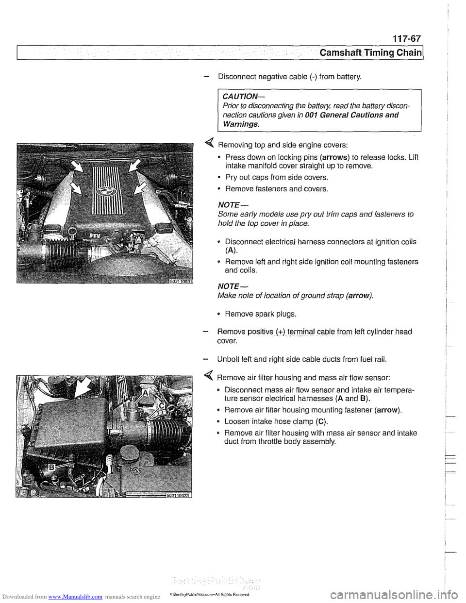
4 Removing top and side engine covers:
Press down on locking pins (arrows) to release locks. Lifl
intake manifold cover straight up to remove.
Pry out caps from side covers.
Remove fasteners
and covers.
NOTE-
Some early models use
pry out trim caps and fasteners to
hold the top cover in place.
Disconnect electrical harness connectors at ignition coils
(A).
Remove left and right side ignition coil mounting fasteners
and coils.
NOTE-
Make note of location of ground strap (arrow).
Remove spark plugs.
- Remove posltlve (+) terminal cable from left cylrnder head
cover.
- Unbolt left and right side cable ducts from fuel rail
Remove air filter housing and mass air flow sensor:
Disconnect mass air flow sensor and intake air tempera-
ture sensor electrical harnesses
(A and B).
Remove air filter housing mounting fastener (arrow)
Loosen intake hose clamp
(C).
Remove air filter housing with mass air sensor and intake
duct from throttle body assembly.
Page 306 of 1002

Downloaded from www.Manualslib.com manuals search engine
I Camshaft Timins Chain
4 Using special tool 11 2 450, rotate engine clocltwise to TDC
with number one cylinder cam lobes facing each other (ar-
rows)
as shown.
4 Lock crankshaft in TDC position with BMW special tool 11 3
200 (arrow).
- Remove BMW special tool 11 2 450 and remove hub.
- Remove upper engine oil pan. See 119 Lubrication.
- Remove alternator. See 121 Battery, Starter, Alternator.
- Remove retaining bolt for oil dipstick tube from upper timing
chain cover on right side.
- Remove camshaft position sensor from right upper timing
chain cover.
< Remove right upper timing chain cover:
Remove chain tensioner
(A).
CAUTIOG
Tensioner is under spring tension. Release slowly. 1
Release fasteners (arrows) and remove cover
Page 315 of 1002

Downloaded from www.Manualslib.com manuals search engine
Camshaft Timing chain/
Camshaft timing, checking and adjusting
(M62 engine)
WARNING -
Allow engine to cool before beginning this procedure. 1
- Working inside luggage compartment, disconnect negative
battery cable.
CAUTIOI\C
Prior to disconnecting battery cable, read the battery discon-
nection cautions given
in 001 General Cautions and
Warninss.
4 Removing plastic top covers:
Press down on locking pins (arrows) to release locks. Lift
intake manifold cover straight up to remove.
Pry out caps from side covers.
Remove fasteners from beneath
caDs. Lift off covers.
4 Remove air filter housing and ducts:
Disconnect mass air flow sensor and intake air tempera-
ture sensor electrical harnesses
(A and B).
Remove air filter housing mounting fastener (arrow).
Release hose clamp at intake air duct on base of air filter
housing.
Loosen intake hose clamp
(C) and release hose from
mass air flow sensor.
Remove hose at idle air stabilizer.
Release hose clamp at throttle body and remove hose.
Remove upper air filter housing with mass air flow sensor.
- Unbolt left and right side cable ducts from fuel rail.
Page 335 of 1002

Downloaded from www.Manualslib.com manuals search engine
... . . Lubrication sy=
Upper oil pan, removing and installing (V-8)
The engine oil pan removal procedure requires that the en-
gine be supported from the top and the front suspension
sub-
frame be lowered.
- Disconnect negative (-) battery cable
4 Lift hood into assembly position.
- While supporting hood, disconnect support struts.
Open hood
fully and lock in piace by installing bolts
(arrow) in left and right hinges to lock hood in place
4 Remove engine top cover:
- Early version: Pry off caps (arrows) and remove fasteners.
Late version: Depress fasteners (arrows) and lift cover.
4 Remove air filter housing and mass air flow sensor:
Disconnect mass air flow sensor
(A) and intake air temper-
ature sensor
(B) electrical harness connectors.
Remove air filter housing mounting fastener (arrow)
Loosen
intake hose clamps (C and D).
Remove air filter housing with mass air flow sensor.
Remove intake hose from throttle body.
Page 351 of 1002

Downloaded from www.Manualslib.com manuals search engine
120-3
Ignition System
Warnings and cautions
The ignition system produces dangerous high voltage. In ad-
dition the sensitive electronic components can be damaged
if
proper precautions are not adhered to.
WARNING-
* Do not touch or disconnect any cables from the coils while
the engine is running or being
cranked by the starter.
The ignition system produces high voltages that can be
fatal. Avoid contact with exposed terminals. Use ex-
treme caution when working on a car with the ignition
switched on or the engine running.
- Connect and disconnect tlie DME system wiring and
test equipment leads only when the ignition is
OFF:
Before operating the starter without starting the engine
(for example when
making a compression test) always
disable the ignition.
CA
U TIOW-
Do not attempt to disable the ignition by removing the coils
from the spark plugs.
Connect or disconnect ignition system wires, multiple
wire connectors, and ignition test equipment leads only
while the ignition is
off Switch multimeter functions or
measurement ranges only with the test probes discon-
nected.
* Do not disconnect the battery while the engine is run-
ning.
A high impedance digital multimeter should be used for
all voltage and resistance tests. An LED test light
should be used in place of an incandescent-type test
lamp.
In general, make test connections only as specified by
BMW as described in this manual, or as described by
the instrument manufacturer.
Engine management
BMW €39 engines use an advanced engine management
system known as Digital Motor Electronics (DME). DME in-
corporates on-board diagnostics, fuel injection, ignition and
other engine control functions. DME variants are listed in
Table a. Engine management systems.
Second generation On-Board Diagnostics
(OED II) is incor-
porated into the engine management systems used on the
cars covered by this manual. Use a BMW-specific electronic
scan tool, or a "Generic"
OED II scan tool to access Diagnos-
tic Trouble Codes (DTCs). DTCs can help pinpoint ignition
ine management problems.
Page 359 of 1002

Downloaded from www.Manualslib.com manuals search engine
Ignition System
- Turn ignition on and check for battery voltage,
If battery voltage is not present,
checlt wire between termi-
nal
15 and the unloader relay. See ELE Electrical Wiring
Diagrams.
- Turn ignition off.
Remove coil and inspect coil housing for hairline
cracks or
leaking casting material. Replace any
cracked or leaking coil.
NOTE-
A leaky coil may indicate a faulty Engine Control Module
(ECM). Check ECM before installing a new coil.
CAUTION-
Note location of coilground straps before coil removal; rein-
stall in the same location.
Use a multimeter to test:
Coil primary resistance at coil terminals.
Sparlt plug connector resistance.
* Compare results to specification in Table c. lgnition coil
resistance.
Table c. Ignition coil resistance
Coil secondary
resistance
Spark plug connector:
Bosch 1 .O I( ohm t 20%
1.8 ir ohm t 20%
Component
Co~l prlmary
resistance
- Replace ignition coil or sparlt plug connector if resistance
readings do not meet specifications.
4 Remove ignition coil to be tested.
Install
BMW special tool 12 7 030 (A) on coil to be tested.
Connect ground jumper between coil mounting point
(B)
and engine ground point (C).
Clip scope high pick-up lead (D) around ignition lead.
Start engine.
Compare scope pattern with diagrams in Oscilloscope
di-
agnostic diagrams.
NOTE-
When replacing ignition coils, ensure that the replacements
Terminal
1 (-) and 15 (+)
are
from the same manufacturer with the same partlcode
numbers. If individual coils with the correct specifications are
not available. all coils should be
re~laced.
Resistance
0.8 ohms
Page 367 of 1002

Downloaded from www.Manualslib.com manuals search engine
121-1
121 Battery. Starter. Alternator
General ........................... .I2 1.2
Special tools ........................ .I2 1.2
Engine electrical system ............... .I2 1.2
Battery Safety Terminal ............... .I2 1.3
Warnings and cautions ................. 121 -4
Battery ............................ 121-5
Battery testing ...................... .I2 1.5
Hydrometer testing ................... .I2 1.5
Battery open-circuit voltage test ......... .I2 1.6
Battery load voltage test ................ 121 -6
Closed-circuit current measurement ..... .I2 1.7
Battery charging ...................... 121 -9
Battery safety terminal, replacing ......... 121-9
Alternator (generator) ............. .I2 1.10
Alternator. basic .................... .I2 1.11
Alternator with multi-function
control (MFR)
...................... .I2 1.11
Water-cooled alternator ............... 121 -12
Charging System Troubleshooting . 121-12
Charging system quick-check .......... 121-13
Charging system. checking ............ 121-13
Alternator. removing and installing
(6-cylinder engine)
.................. 121 -1 5
Alternator. removing and installing
(M62 engine. air cooled)
.............. 121-16
Alternator. removing and installing
(M62 TU engine. water cooled) ......... 121-1 8
Starter ........................... 121 -1 9
Starter troubleshooting ............... 121 -1 9
Starter. removing and installing
(6-cylinder engine)
.................. 121-20
Starter. removing and installing
(V-8 engine)
........................ 121 -21
Solenoid switch. removing and installing . . 121-23