2000 BMW 528i eccentric shaft
[x] Cancel search: eccentric shaftPage 132 of 1002

Downloaded from www.Manualslib.com manuals search engine
11 3-38
I Cylinder Head Removal and Installation
< Turn eccentric shaft of special tool to pretension intake cam-
shaft bearing caps. Remove nuts on all intake camshaft bear-
ing caps.
- Slowly release tension on eccentric shaft and remove BMW
spec~al tools. Remove bearing caps and set as~de in order.
Remove camshaft and store safely.
- Repeat procedure for exhaust camshaft.
4 Secure hydraulic lifters in lifter bores using BMW speclal tool
11 3 250, or remove lifters using a magnetic pick-up tool.
With lifters secure or removed, lift out camshaft bearing car-
riers from cylinder head.
Use care to not let hydraulic lifters fall out as camshaft car-
rier is removed.
Hydraulic lifters should be stored
ln an uprightpositlon.
Used hydraulic lifters must be reinstalled into their orig-
inal lifter bores.
4 Remove intake camshaft position sensor (arrow) from side
of cylinder head.
4 Remove secondary chain lowerguide bolts (arrow). Remove
chain guide.
Page 137 of 1002

Downloaded from www.Manualslib.com manuals search engine
.-
Cylinder Head Removal and Installation
4 Rotate camshafts until intake and exhaust lobes for cylinder
1 face each other (arrows).
CAUTION-
Be sure that cranlcshaft is stillpositioned at least 30" away
from
TDC.
- Place bearing caps on cams, but do not install retaining nuts.
4 Fit BMW special tool 11 3 260 (A) and 11 3 270 (B) to cylin-
der head over intake camshaft and screw long bolts (arrows)
into spark plug threads.
CAUTIOI\C
Do not overtighten bolts in spark plug holes.
Turn eccentric shaft of special tool to pretension
bearing
caps. Install and torque nuts on intake camshaft bearing
caps.
Tightening torque Camshaft bearing
cap to cylinder head (M7) 14 Nm (10 ft-lb)
Release tension on eccentric
shaft and remove BMW special
tools
11 3 2601270.
Repeat procedure for exhaust camshaft.
CAUTION-
After the camshafts are installed, a minimum waiting time is
required for the hydraulic lifters to 'bleed down" before bring-
ing the crankshaft andpiston back to top
deadcenter. When
the camshafts are removed, the hydraulic lifters can expand.
This expansion can cause increased valve lift when the cam-
shafts are bolted down, possibly resulting in piston interfer-
ence.
Crankshaft
I valve timing waiting times
68.F (20°C) and higher 4 minutes
50-68"F(10-20°C) 11 minutes
32-5O0F(O-10°C) 30 minutes
Page 192 of 1002

Downloaded from www.Manualslib.com manuals search engine
.
Cylinder Head and Valvetrain
< Remove cylinder head cover retaining studs (arrows) from
center and rear of cylinder head.
< Remove spark plugs and install BMW special tool 11 3 260
(A) and 11 3 270 (6) to cylinder head. Tighten tool retaining
bolts in spark plug bores. Do not overtighten bolts.
Tightening
torque
BMW special tool 11 3 260 I1 1 3 270 to 23 Nm (17 It-lb)
cylinder head
- Remove intake camshaft bearing cap for cylinder number 1.
CA UTIOG
Intake camshaft bearing cap 1 is centered with adapter
sleeves. To avoid
can~sllaft daniage, it must be removed bs-
fore any other caps.
Turn eccentric shaft on special tool until pressure is applied
to camshaft bearing caps.
- Remove remaining bearing cap mounting nuts
- Slowly release pressure on camshaft bearing caps by turning
eccentric shaft. Remove bearing caps and camshaft. Repeat
procedure on remaining camshaft.
CAUTION-
Camshaft bearing caps must be reinstalled in their original lo-
cations.
NOTE-
The camshaft bearing caps are coded with a letter anda
number. For example,
'XI" is the first exhaust camshaft
bearing cap at the front of the engine, and
"El "is the intalce
camshaft bearing cap at the front of the engine.
0 The camshafts are stamped with a code letter - "E" for the
intake side and 'MA" for the exhaust side.
0 "E is for Einlap, (German for intake) and 'XA"is for Auspuff,
(German for exhaust).
Page 200 of 1002

Downloaded from www.Manualslib.com manuals search engine
..--.
I Cylinder Head and Valvetrain - I
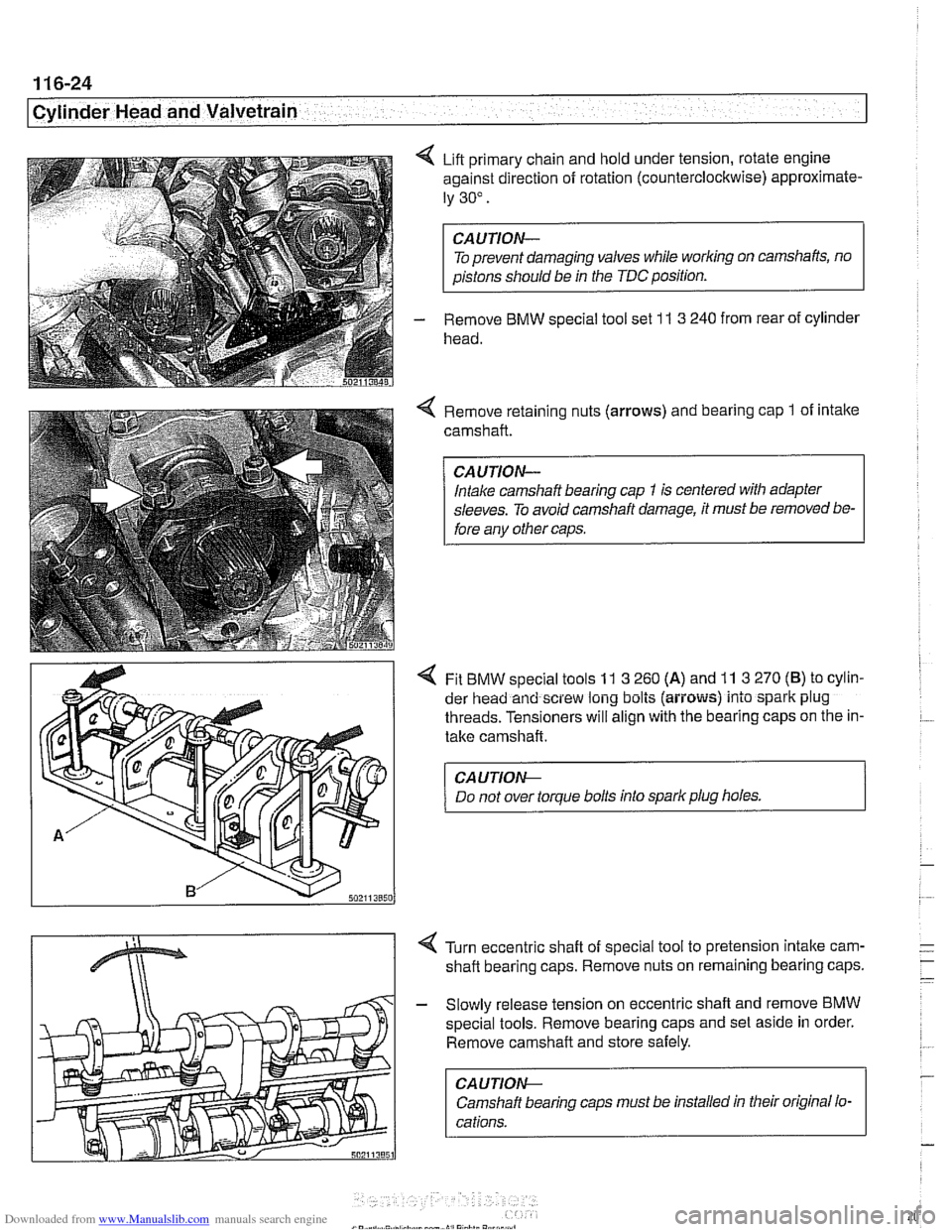
4 Lift primary chain and hold under tension, rotate engine
against direction of rotation (counterclockwise) approximate-
ly 30".
To prevent damaging valves while
worlcing on camshafts, no
aistons should be in the TDC position.
- Remove BMW special tool set 1 I 3 240 from rear of cylinder
head.
Remove retaining nuts (arrows) and bearing cap
1 of intake
camshaft.
Intake camshaft bearing cap
1 is centered with adapter
sleeves. To avoid camshaft damage, it must be removed be-
fore anv other caos.
4 Fit BMW special tools 11 3 260 (A) and 11 3 270 (B) to cylin-
der head and screw long bolts (aiiows) into spark plug
threads. Tensioners will align with the bearing caps on the in-
take camshaft.
CA UTION--
Do not over torque bolts into spark plug holes. 1
4 Turn eccentric shaft of special tool to pretension intake carn-
shaft bearing caps. Remove nuts on remaining bearing caps.
- Slowly release tension on eccentric shaft and remove BMW
special tools. Remove bearing caps and set aside in order.
Remove camshaft and store safely.
CA U TIOW-
Camshaft bearing caps must be installed in their original lo-
cations.
Page 203 of 1002

Downloaded from www.Manualslib.com manuals search engine
-- - . .- -,
Cylinder Head and Valvetrain
4 Rotate camshafts so that intalte and exhaust lobes for cylin-
der
1 face each other (arrows).
CAUJION-
A minimum waiting time is required for the hydraulic lifters to
'bleed down"after installing the camshafts into the cylinder
head, before bringing the piston to TDC. When the camshafts
are removed, the hydraulic lifters can expand. This expan-
sion can cause increased valve lift when the camshafts are
bolted down, possibly resulting in piston interference.
Place bearing caps on cams, but do not install retaining nuts.
4 Fit BMW special tool 11 3 260 (A) and 11 3 270 (B) to cylinder
head over
intalte camshaft and screw long bolts (arrows)
into spark plug threads.
CA UTION-
Do not overtighten bolts into spark plug holes.
< Turn eccentric shaft of special tool to pretension bearing
caps. Install and torque nuts on intake camshaft bearing
caps.
Tightening torque Camshaft bearing cap
to cylinder head (M7) 14 Nm (10 it-ib)
- Release tension on eccentric shaft and remove BMW special
tools
11 3 2601270.
- Repeat procedure for exhaust camshaft.
NOTE-
Observe waiting time for lifter bleed down before continuing
with camshaff installation.
Crankshaft
I valve timing waiting times
68°F (20°C) and higher 5 minutes
50-6S°F(10-20°C) 15 minutes
32-50DF(O-10°C) 30 minutes
Page 692 of 1002

Downloaded from www.Manualslib.com manuals search engine
320-34
I Steerins and Wheel Alignment
Front toe and toe difference angle
Toe is the difference in the distance between the front of the
front wheels and the rear of the front wheels. It is adjusted by
altering the length of the tie rods.
Toe difference angle determines the progressively different
paths taken by the front wheels as the car is turning. In
V-8
models, it is set by the pitman arm adjustment, but depends
on accurate setting of the toe.
Toe adjustments should only be made on specialized align-
ment equipment and only with the car in normal loaded posi-
tion, described below.
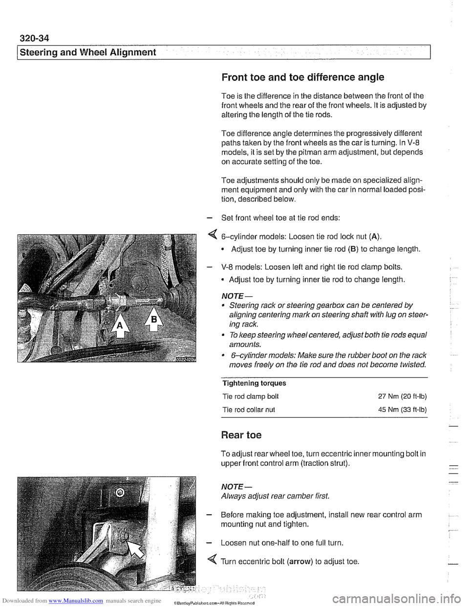
- Set front wheel toe at tie rod ends:
4 6-cylinder models: Loosen tie rod lock nut (A).
Adjust toe by turning inner tie rod (B) to change length
- V-8 models: Loosen left and right tie rod clamp bolts.
Adjust toe by turning inner tie rod to change length.
NOTE-
* Steering rack or steering gearbox can be centered by
aligning centering mark on steering shaft
with lug on steer-
ing rack.
To keep steering wheel centered, adjust both tie rods equal
amounts.
&cylinder models: Make sure the rubber boot on the rack
moves freely on the tie rod and does not become twisted.
Tightening torques
Tie rod clamp bolt
Tie rod collar
nut
27 Nm (20 ft-lb)
45 Nm (33 A-lb)
Rear toe
To adjust rear wheel toe, turn eccentric inner mounting bolt in
upper front control arm (traction strut).
NOTE-
Always adjust rear camber first.
- Before making toe adjustment, install new
mounting nut and tighten.
- Loosen nut one-half to one full turn.
4 Turn eccentric bolt (arrow) to adjust toe. rear
control arm
Page 722 of 1002

Downloaded from www.Manualslib.com manuals search engine
330-26
/ Rear Suspension
Remove inner control arm eccentric nut and bolt (A)
Remove control arm ball joint nut (6). Press ball joint out
of wheel bearing carrier.
Lifl out control arm.
Installation is reverse of removal, noting the following:
Use previously made
marks to install eccentric bolt and
nut.
Always use new self-locking nuts.
Tighten fasteners to final torque only after vehicle has
been lowered and suspension has settled.
0 Have car professionally aligned when job is complete.
Tightening
torques
Road wheel to hub 120klONm
(89 i7 ft-lb)
Upper front control arm (traction strut) to 60
Nm (44
ft-lb)
subframe (rear toe adjusting bolt)
Upper front control arm (traction strut) to wheel
65 Nm (48 ft-lb)
carrier
Rear axle assembly, removing and
installing (sedan models)
In case of damage to the subframe, or if a pressed-in bushing
is worn, remove
subframe by removing complete axle assem-
bly.
- Raise car and remove rear wheels.
WARNING-
Make sure the car is firmly supported on jack stands de-
signed for the purpose. Place jack stands underneath struc-
tural chassis points. Do not place
jack stands under
suspension parts.
- Remove exhaust system. See 180 Exhaust System
- Detach driveshaft from differential. See 260 Driveshaft.
- Remove brake caliper and brake disc. Hang brake caliper
aside with stiff wire. Do not disconnect brake fluid hose. See
340 Brakes.
- Remove lefl and right ABS sensors from wheel bearing car-
riers.
- Disconnect parking brake cable from brake shoe expander.
See 340 Brakes.
- Remove heat shield from above driveshaft.
Page 735 of 1002

Downloaded from www.Manualslib.com manuals search engine
330-39
I Rear suspension1
- Remainder of installation is reverse of removal, noting the fol-
lowing.
Models with coil springs: Fit spring correctly in lower spring
seat.
* Models with air suspension: Fit eccentric lug at bottom of
air spring in recess of wheel carrier spring seat.
Always use new self-locking nuts.
- Make sure all threaded bolts, nuts and mating surfaces are
clean.
a Tighten fasteners to final torque only after vehicle has
been lowered and suspension has settled.
Stake axle collar nut afler tightening.
Tightening torques
ABS pulse sensor to wheel bearing 8 Nm (6
ft-lb)
carrier
Air spring to wheel bearing carrier 20 Nm (15 ft-lb)
Brake rotor to hub 16 Nm (12
it-lb)
Rear axle shaft to hub (M27) 300 Nm (221 ft-lb)
Rear brake pad carrier (caliper) to wheel 65 Nm (48 ft-lb)
bearing carrier
Road wheel to hub
120ilONm
(89 k7 ft-lb)
Swing arm to wheel bearing carrier 256 Nm (189 it-lb)
Upperfrontcontrol arm (traction strut) to 65 Nm (48 ft-lb)
wheel carrier
Upper rear control arm to wheel carrier 142 Nm (105 ft-lb)
Rear wheel bearing, replacing
< The rear wheel bearing is integrated with its mounting flange.
1. Torx bolt
2. Wheel bearing and mounting flange
3. Wheel hub
4. Collar nut
- Raise rear end of car and remove wheel.
WARNING -
Make sure the car is firmly supported on jaclc stands de-
signed for the purpose. Place jack stands underneath struc-
tural chassis points. Do not place jack stands under
suspension parts.