2000 BMW 528i Fuel trim
[x] Cancel search: Fuel trimPage 3 of 1002

Downloaded from www.Manualslib.com manuals search engine
YOU are now in Volume I
I
Foreword ................... .. ........................................................................\
.......... v
Index
........................ .. ................................................................ rear of manual
General, 001 General Warnings and Cautions 002 Vehicle Identification and VIN Decoder
Maintenance OiO 020 Maintenance
Engine
100 Engine-General 110 Engine Removal and Installation
113 Cylinder Head Removal and
Installation
116 Cyiinder Head and Valvetrain 117 Camshaft Timing Chain
119 Lubrication System
200 Transmission-General
2 Transmission 210 clutch 230 ManualTransmission
I20 Ignition System
121 Battery, Starter, Alternator
130 Fuel Injection
160 Fuel Tank and Fuel Pump 170 Radiator and Cooling System
180 Exhaust System
240 Automatic Transmission
250 Gearshift Linkage 260 Driveshaft
Suspension, 300 Suspension, Steering and 330 Rear Suspension
Brakes-General 331 Final Drive
Steering and No Front Suspension 340 Brakes
320 Steering and Wheel Alignment
400 Body-General
410 Fenders, Engine Hood 411 Doors
412 Trunk Lid, Tailgate
510 Exterior Trim, Bumpers 512 Door Windows
Equipment 513 Interior Trim
7
Equipment and 720 seat Belts
Accessories 721 Airbag System (SRS)
OBD On-Board Diagnostics
. ............ ..
515 Central Lociting and
Anti-Theft
520 Seats 540 Sunroof
.................................................................... Foreword .............................. .. v
Index ................... .. ................................................................ rear of manual
Electrical
6 system
600 Electrical System-General 620 Instruments
610 Electrical Comoonent Locations 630 Liohts
611 wipers and washers 612 Switches eati in^ and Air Conditioning
Radio
. ........... ........ .........................
Electrical Wiring Diagrams
Page 33 of 1002

Downloaded from www.Manualslib.com manuals search engine
020 Maintenance
General ........................... .02 0.2
Special tools ........................ .02 0.2
Service Interval Indicator (Sll) ........... .02 0.3
Service Interval Indicator (Sll), resetting ... .02 0.3
Inspection I, Inspection 11 ............... .02 0.5
Maintenance Tables ................ .02 0.6
Fluid and Lubricant Specifications .. .02 0.9
Fluids and lubricants ................. .02 0.10
Engine Oil Service ................ .02 0.1 I
Engine oil. checking level ............. .02 0.12
Engine oil and filter. changing .......... .02 0-13
Engine Compartment Maintenance . .02 0.14
Accelerator and linkage ............... .02 0.14
Air filter. replacing ................... .02 0.1 4
Cooling system service ............... .02 0.15
Engine drive belt service .............. .02 0.16
Idlespeed .......................... 020-19
Catalytic converter and oxygen sensors .. .02 0.19
Power steering fluid, checking level ..... .02 0.20
Spark plugs ........................ .02 0.20
Spark plugs, replacing ................ .02 0.21
Interior ventilation microfilter, replacing ... .02 0.22
Other Mechanical Maintenance ..... .02 0.22
Battery, checking. cleaning. and replacing .02 0-22
Brake fluid. replacing ................. .02 0-24
Brake pad 1 rotor wear. checking ........ .02 0.24
Brake system, inspecting ............. .02 0.25
Parking brake. checking ............... 020-25
Clutch fluid. checking ................. 020-26
Differential oil level. checking ........... 020-26
Drive axle joint (CV joint) boots. inspecting 020-27
Exhaust system. inspecting ............ 020-27
Fuel filter. replacing .................. 020-27
Fuel tank and fuel lines. inspecting ...... 020-28
Suspension. front. inspecting ........... 020-29
Suspension. rear. inspecting ........... 020-29
Tires. checking inflation pressure ........ 020-29
Tires. rotating ....................... 020-29
Transmission service. automatic ........ 020-29
Transmission service. manual .......... 020-30
Transmission fluid. checking and filling
(manual transmission)
................ 020-30
Wheels. aligning ..................... 020-30
Body and Interior Maintenance ..... 020-31
Body and hinges. lubricating ........... 020-31
Exterior washing ..................... 020-31
Interior care ........................ 020-31
Leather upholstery and trim ............ 020-31
Polishing ........................... 020-32
Seat belts .......................... 020-32
Special cleaning ..................... 020-32
Washing chassis ..................... 020-32
Waxing ............................ 020-32
Windshield wiper blade maintenance ..... 020-33
Page 53 of 1002

Downloaded from www.Manualslib.com manuals search engine
020-21
Maintenance
Spark plugs, replacing
E39 engines use a coil-over-spark plug configuration, with
one ignition coil above each spark plug. Sparks plugs should
be removed only after the engine has cooled.
Remove engine
cover(s) over ignition coils:
Remove acoustic cover over fuel injectors
I intake
manifold.
6-cylinder engine: Remove oil filler cap.
Remove plastic trim covers (arrows).
Remove cover hold-down bolts. Remove coil
cover(s)
6-cylinder engine: Temporarily reinstall oil filler cap to
keep out contaminants.
Remove ignition coil grounding harnesses (arrows). 6-cylin-
der coils shown,
V-8 engine is similar.
< Remove ignition coils:
Pull up on spring clips to disconnect ignition coil harness
connectors.
Remove coil mounting bolts. Pull coils up and off spark
plugs.
- Remove spark plugs.
Page 77 of 1002

Downloaded from www.Manualslib.com manuals search engine
Engine Removal and lnstallationl
< Remove positive battery cable and intake manifold cover:
Remove protective cover from positive (+)jump start post
(4.
Loosen and remove battery lead mounting nut.
Remove lead and push down through intake manifold
Remove trim covers
(arrows) from fuel injector cover.
Remove cover hold down bolts and lift off cover.
Working above engine, disconnect the following:
Vent line from cylinder head cover (A).
M52 engine: Oxygen sensor connectors (8).
Electrical harness connector from intalte camshaft VANOS
solenoid valve
(C).
M52 engine: Disconnect electrical harness connectors at
throttle valve position switch
(D), ASC valve position switch
(E), fuel injector harness (F) and vent valve (G).
CAUTION-
Be sure to mark oxygen sensor harness connectors so that
they can be reassembled correctly Do not interchange con-
nectors.
4 M52 TU, M54 engine: Disconnect fuel injector electrical con-
nectors from injectors.
Use small screwdriverto pry one corner of wire lock clip on
fuel injector
1 connector.
Repeat for all injectors.
Lifl off connector loom and lay aside.
Page 103 of 1002

Downloaded from www.Manualslib.com manuals search engine
11 3-9
Cylinder Head Removal and Installation
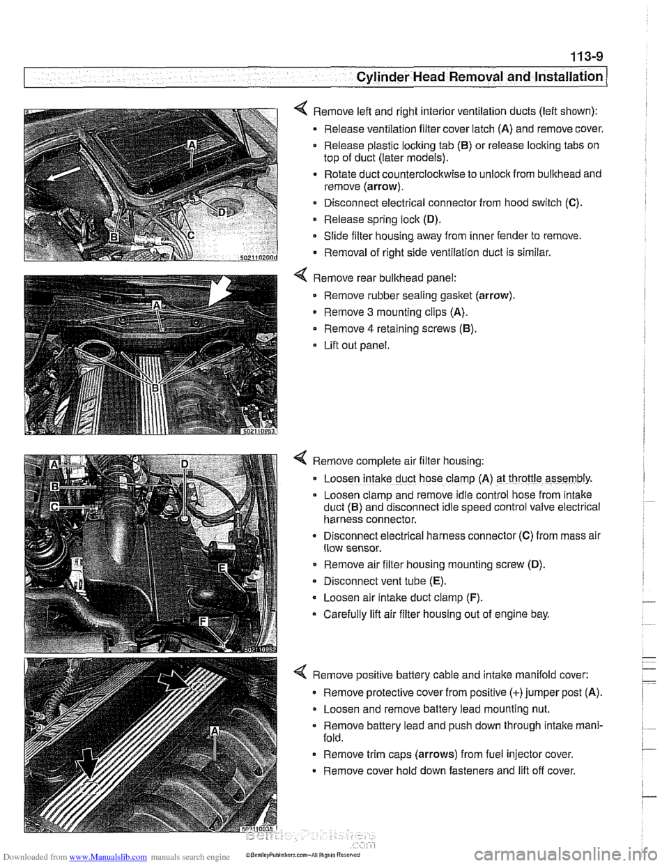
< Remove left and right interior ventilation ducts (left shown):
Release ventilation filter cover latch (A) and remove cover.
Release plastic locking tab
(6) or release locking tabs on
top of duct (later models).
Rotate duct counterclockwise to unlock from bulkhead and
remove (arrow).
Disconnect electrical connector from hood switch
(C).
Release spring lock (D).
Slide filter housing away from inner fender to remove.
Removal of right side ventilation duct is similar.
Remove rear bulkhead panel: Remove rubber sealing
gasket (arrow).
0 Remove 3 mounting clips (A).
Remove
4 retaining screws (6).
Lift out panel.
< Remove complete air filter housing:
Loosen
intake duct hose clamp (A) at throttle assembly.
Loosen clamp and remove idle control hose from
~ntake
duct (6) and disconnect Idle speed control valve electr~cal
harness connector.
Disconnect
electr~cal harness connector (C) from mass alr
flow sensor.
Remove air filter housing mounting screw (D).
Disconnect vent tube
(E).
Loosen air intake duct clamp (F).
Carefully lift air filter housing out of engine bay.
4 Remove positive battery cable and intake manifold cover:
Remove protective cover from positive (+)jumper post (A).
Loosen and remove battery lead mounting nut.
Remove battery lead and push down through intake mani-
fold.
Remove trim caps (arrows) from fuel injector cover.
Remove cover hold down fasteners and lift off cover.
Page 117 of 1002

Downloaded from www.Manualslib.com manuals search engine
- --
Cylinder Head Removal and Installation 1 --
< Remove complete air filter housing assembly with mass air
flow sensor:
Loosen
intalte duct hose clamp (A) at throttle assembly.
Loosen clamp and remove idle control line from intake duct
(B) and disconnect idle speed control valve electrical har-
ness connector.
Disconnect electrical harness connector
(C) from mass air
flow sensor.
Remove air filter housing mounting screw
(D).
Disconnect vent tube (E).
. Loosen air intalte duct clamp (F).
Carefully lifl air filter housing, mass air flow sensor, and in-
take duct hose out of engine bay.
4 Disconnect positive battery cable and remove intake rnani-
fold cover:
Remove protective cover from positive (+)jumper post.
Loosen and remove battery lead mounting nut (A).
Remove lead and push down through intake manifold.
* Remove trim covers (arrows) from fuel injector cover.
Remove cover hold down fasteners and lifl off cover.
4 Worlting above engine, disconnect the following:
Vent line from cylinder head cover. To remove, pinch clips
(arrows).
Electrical harness connector from VANOS solenoid valve
(A).
- Remove oxygen sensors and exhaust manifolds. See 180
Exhaust System.
CAUTION-
Remove oxygen sensors before removing exhaust mani-
fold to prevent damage.
Label oxygen sensor harness connectors so that they
can be reassembled correctly Do not interchange con-
nectors.
NOTE-
Front exhaust manifold must be removed before rear
manifold.
Page 121 of 1002

Downloaded from www.Manualslib.com manuals search engine
11 3-27
Cylinder Head Removal and Installation
< Remove fuel rail mounting bolts (arrows):
- Carefully pry fuel rail off manifold.
Separate fuel line support bracket at rear of intake mani-
fold.
Guide fuel
line(s) out of rear of engine compartment while
lifting fuel rail out.
4 Remove intake manifold mountino hardware (arrows).
I from falling into the engine intake. I
4 Remove cylinder head top cover:
- Remove plastic trim caps (arrows).
Remove cover hold down fasteners and
lilt off cover.
Page 303 of 1002

Downloaded from www.Manualslib.com manuals search engine
Camshaft Timing chain1
- Disconnect negative cable (-) from battery.
CAUTION-
Prior to disconnecting the battery, read the battery discon-
nection cautions given
in 001 General Cautions and
Warnings.
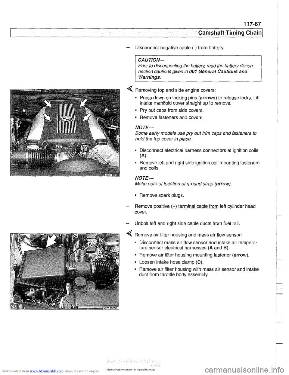
4 Removing top and side engine covers:
Press down on locking pins (arrows) to release locks. Lifl
intake manifold cover straight up to remove.
Pry out caps from side covers.
Remove fasteners
and covers.
NOTE-
Some early models use
pry out trim caps and fasteners to
hold the top cover in place.
Disconnect electrical harness connectors at ignition coils
(A).
Remove left and right side ignition coil mounting fasteners
and coils.
NOTE-
Make note of location of ground strap (arrow).
Remove spark plugs.
- Remove posltlve (+) terminal cable from left cylrnder head
cover.
- Unbolt left and right side cable ducts from fuel rail
Remove air filter housing and mass air flow sensor:
Disconnect mass air flow sensor and intake air tempera-
ture sensor electrical harnesses
(A and B).
Remove air filter housing mounting fastener (arrow)
Loosen intake hose clamp
(C).
Remove air filter housing with mass air sensor and intake
duct from throttle body assembly.