Page 278 of 1002

Downloaded from www.Manualslib.com manuals search engine
I Camshaft Timing Chain
- Using new gasket, install VANOS control unit to cylinde~
head.
Reinstall engine support eye.
Tightening torques VANOS control unit to cylinder head
M6 nut 10 Nm (89 in-lb)
M7 nut 14 Nm (10 ft-ib)
4 Insert and tighten VANOS hydraulic piston set screws on
intake and exhaust camshafts.
CAUTIOI\C
Set screws have left hand thread Tighten counterclocltwise.
Tightening torque
Hydraulic piston
to splined shaft 10 Nm (89 in-lb)
(set screw)
4 Replace sealing caps inside VANOS control unit with BMW
special tool 11 6 170, or short flat nosed pliers.
Insert and secure VANOS sealing plugs (arrows), using new
sealing O-rings.
Tightening torque Sealing plug to VANOS control unit 50 Nm (37
it-lb)
Remove compressed air fitting from VANOS control unit
Fit VANOS oil line banjo bolt with new seals. Attach oil line to
VANOS control unit.
Tightening torque Oil line to VANOS control unit (banjo bolt) 32
Nm (24
it-lb) -
Page 280 of 1002
Downloaded from www.Manualslib.com manuals search engine
Camshaft Timing Chain
Insert BMW special tool 11 4 220 in cylinder head and bring
adjustment screw into contact with tensioning rail.
NOTE-
BMW special tool 11 4 220 is an adjustable primary chain
tensioner that simulates the function of the tensioner.
Preload primary chain tensioner rail:
Tighten adjusting screw on
BMW special tool 11 4 220.
Tightening torque
Primary chain tensioner preload 0.7 Nm (6 in-lb)
4 Unscrew oil pressure pipe from VANOS control unit. Remove
banjo bolt from oil pressure line and install BMW special tool
11 3 450.
CA UTIOPI-
Cover top of VANOS control unit with lint-free shop cloth. At-
tachment of compressed air line will force oil to spray out of
- Connect compressed air line to air fitting. Apply air pressure
set to
2 - 8 bar (30 - 110 psi).
Page 281 of 1002

Downloaded from www.Manualslib.com manuals search engine
Camshaft Timing chain1
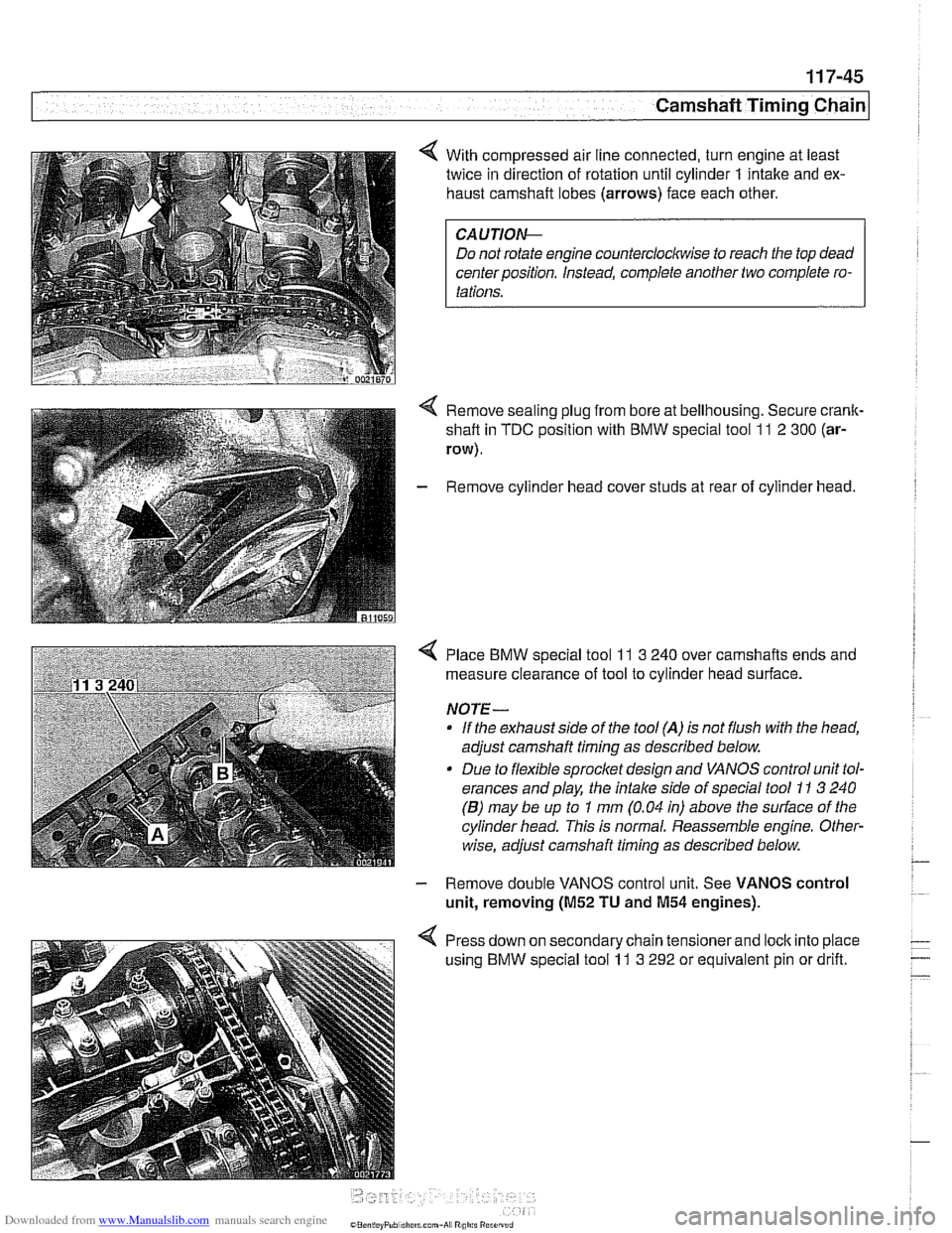
< With compressed air line connected, turn engine at least
twice in direction of rotation until cylinder
1 intake and ex-
haust camshaft lobes (arrows) face each other.
Do not rotate engine counterclockwise to reach the top dead
center position. Instead, complete another two complete ro-
Remove sealing plug from bore at bellhousing. Secure crank-
shaft in
TDC position with BMW special tool 11 2 300 (ar-
row).
- Remove cylinder head cover studs at rear of cylinder head.
< Place BMW special tool 11 3 240 over camshafts ends and
measure clearance of tool to cylinder head surface.
NOTE-
If the exhaust side of the tool (A) is not flush with the head,
adjust camshaft timing as described below.
Due to flexible sprocket design and VANOS control unit tol-
erances and play, the
intake side of special tool 11 3 240
(B) may be up to 1 mm (0.04 in) above the surface of the
cylinder head. This is normal. Reassemble engine. Other-
wise, adjust camshaft timing as described below.
- Remove double VANOS control unit. See VANOS control
unit, removing
(M52 TU and M54 engines).
< Press down on secondary chain tensionerand lock into place
using BMW special tool
11 3 292 or equivalent pin or drift.
Page 285 of 1002

Downloaded from www.Manualslib.com manuals search engine
-- - -- - -- Camshaft Timing chain1
- Remove camshaft locking tools from rear of camshafts
- Remove BMW special tool 11 4 220 (adjustable primary
chain tensioner). Reinstall primary chain tensioner.
Tightening torque Primary chain tensioner to cylinder head
70
Nm (52 it-lb)
- Remove crankshaft locking tool from transmission bellhous-
ing. Reinstall sealing plug.
- Remove VANOS setup bracket from front of cylinder head
- lnstall VANOS control unit as described earlier in this group.
- Remove compressed air fitting (BMW special tool 11 3 450)
from VANOS control unit.
- Fit VANOS oil line banjo bolt with new seals. Attach oil line to
VANOS control unit.
Tightening torque
Oil line to VANOS control unit (banjo bolt) 32 Nm (24 H-lb)
- Remainder of installation is reverse of removal, noting the fol-
lowing:
lnstall spark plugs.
* lnstall intake camshaft plastic baffle prior to installing cylin-
der head cover. lnstall ignition coil packs and connect elec-
trical harness connectors.
Install radiator cooling fan.
- lnstall air filter housing and top engine cover.
Tightening torque Radiator cooling fan
(VISCOUS clutch) to 40 Nm (30 ft-lb)
coolant pump
Cyitnder head cover to cylinder head 10 Nm (89 in-lb)
Sparlc plug to cylinder head 25 Nm (18 ft-lb)
Page 287 of 1002

Downloaded from www.Manualslib.com manuals search engine
... -.
Camshaft Timing chain1
Timing chains, removing
(M52 TU and M54 engines)
Camshaft timing chain removal requires that the oil pan be re-
moved. See
119 Lubrication System. Also required is re-
moval of the VANOS control
unit and disassembly of the
intake and exhaust camshaft sprocket assemblies as de-
scribed earlier in this repair group.
Special BMW
service tools are needed for timing chain re-
moval and installation. The special tools assure proper timing
of the valvetrain. Precise
marlts to set the timing on the cam:
shafts are not provided for reassembly. Read the procedures
through before beginning the job.
CA
UTION-
If the camshafts are not properly timed, the pistons can con-
tact the valves.
- D~sconnect negative (-) cable from battery.
CAUTION-
* Disconnecting the battery may erase fault code@) stored in
control module memory. Check for fault codes using spe-
cial
BMW diagnostic equipment.
Prior to disconnecting the battery, read the battery dis-
connection
cautfons given in 001 General Cautions
and
Warninqs.
- Remove VANOS control unit. See VANOS control unit, re-
moving
(M52 TU and M54 engines).
Remove sealing plug from crankcase below starter and se-
cure crankshaft with
BMW special tool ll 2 300.
Drain engine cooling system. See 170 Radiator and Cool-
ing System.
Remove belt driven cooling fan, fan shroud, and thermostat
housing. See
170 Radiator and Cooling System.
Remove drive belts. See
020 Maintenance.
NOTE-
Mark direction of belt rotation if reusing belt.
- Remove water pump pulley fasteners and pulley.
- Drain engine oil and remove oil pan as described in 119
Lubrication System.
Page 301 of 1002

Downloaded from www.Manualslib.com manuals search engine
Cp-- Camshaft -- Timing Chain
Secure camshaft sprockets and impulse wheels:
Tighten mounting screws
(A) on exhaust camshaft impulse
wheel to approx.
5 Nm (44 in-lb).
Tighten mounting nuts
(6) on exhaust and intake sprocket
assemblies to approx.
5 Nm (44 in-lb).
Torque down mounting screws (A) and nuts
(6) to iinal
specifications.
Tightening torques Sprocket assembly
to camshaft
initial torque
5 Nrn (44 in-lb)
Sprocket assembly to camshaft
M7 Torx screw (A) 20 Nm (I5 it-lb)
M6 mounting nut (8) 10 Nm (89 in-lb)
- Remove flywheel locking tool from transmission bellhousing
so that crankshaft is no longer secured.
- Remove camshaft loclting tools from rear of camshafts.
4 Crank engine over by hand twice in direction of rotation until
cylinder
1 intake and exhaust camshaft lobes (arrows) face
each other.
- Secure crankshaft in TDC position with BMW special tool
11 2 300.
4 Place BMW special tool 11 3 240 over camshaft ends and
measure clearance of tool to cylinder head surface.
NOTE-
* If the exhaust side of the tool is not flush with the head (gap
A), retime the camshafts as described laler in this repair
group.
Due to flexible sprocket design and VANOS control unit tol-
erances and play, the
intake side of special tool 71 3 240
may be up to
I mm (0.04 in) above the suriace of the cyl-
inder head (gap
B). This is normal. Otherwise, retime the
camshafts as described in
VANOS timing, checking and
adjusting (M52 TU and 11154 engines).
- Remove VANOS setup bracket from front of cylinder head
- Install VANOS control unit. See VANOS control unit, in-
stalling
(01152 TU and M54 engines).
- Install intake camshaft oil baffle
Page 303 of 1002

Downloaded from www.Manualslib.com manuals search engine
Camshaft Timing chain1
- Disconnect negative cable (-) from battery.
CAUTION-
Prior to disconnecting the battery, read the battery discon-
nection cautions given
in 001 General Cautions and
Warnings.
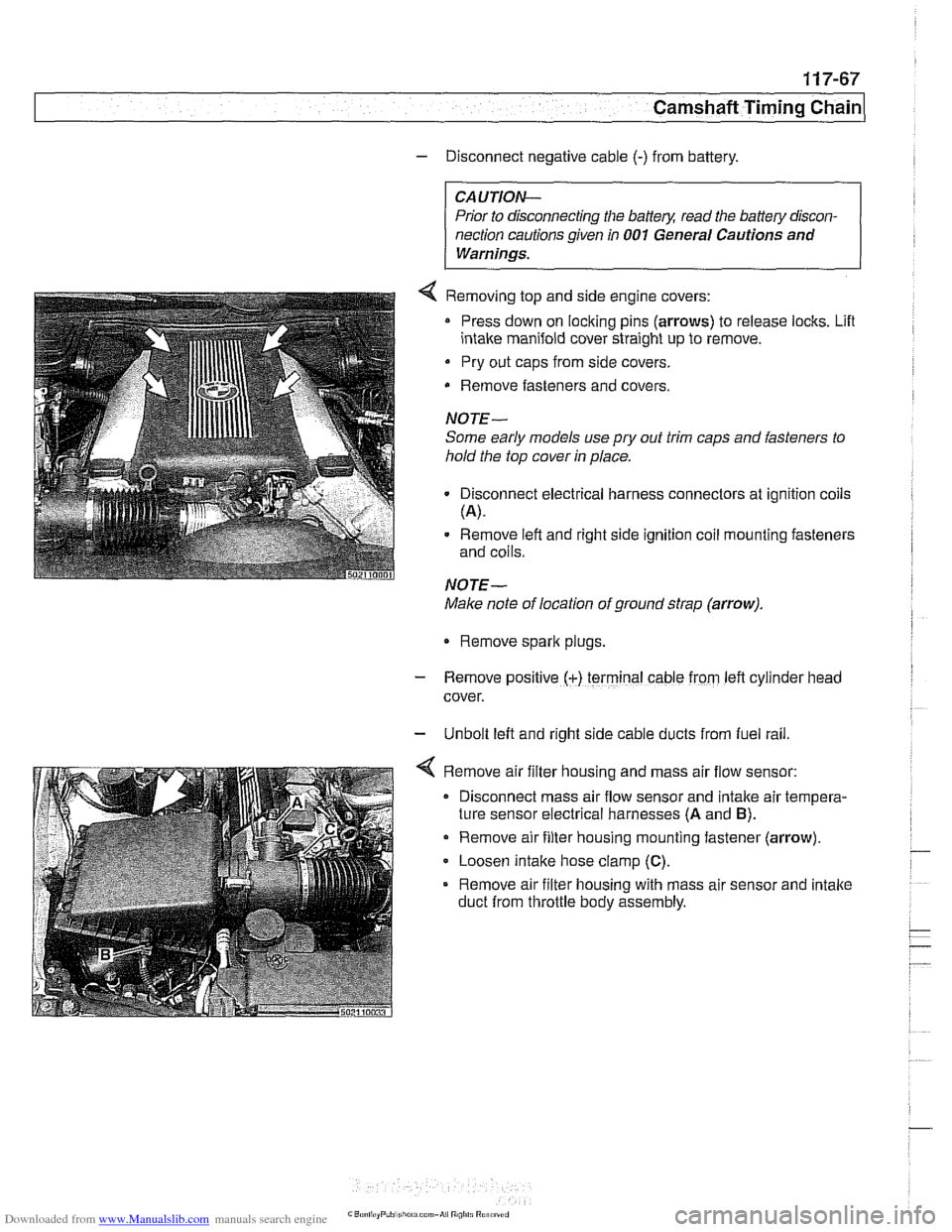
4 Removing top and side engine covers:
Press down on locking pins (arrows) to release locks. Lifl
intake manifold cover straight up to remove.
Pry out caps from side covers.
Remove fasteners
and covers.
NOTE-
Some early models use
pry out trim caps and fasteners to
hold the top cover in place.
Disconnect electrical harness connectors at ignition coils
(A).
Remove left and right side ignition coil mounting fasteners
and coils.
NOTE-
Make note of location of ground strap (arrow).
Remove spark plugs.
- Remove posltlve (+) terminal cable from left cylrnder head
cover.
- Unbolt left and right side cable ducts from fuel rail
Remove air filter housing and mass air flow sensor:
Disconnect mass air flow sensor and intake air tempera-
ture sensor electrical harnesses
(A and B).
Remove air filter housing mounting fastener (arrow)
Loosen intake hose clamp
(C).
Remove air filter housing with mass air sensor and intake
duct from throttle body assembly.
Page 315 of 1002

Downloaded from www.Manualslib.com manuals search engine
Camshaft Timing chain/
Camshaft timing, checking and adjusting
(M62 engine)
WARNING -
Allow engine to cool before beginning this procedure. 1
- Working inside luggage compartment, disconnect negative
battery cable.
CAUTIOI\C
Prior to disconnecting battery cable, read the battery discon-
nection cautions given
in 001 General Cautions and
Warninss.
4 Removing plastic top covers:
Press down on locking pins (arrows) to release locks. Lift
intake manifold cover straight up to remove.
Pry out caps from side covers.
Remove fasteners from beneath
caDs. Lift off covers.
4 Remove air filter housing and ducts:
Disconnect mass air flow sensor and intake air tempera-
ture sensor electrical harnesses
(A and B).
Remove air filter housing mounting fastener (arrow).
Release hose clamp at intake air duct on base of air filter
housing.
Loosen intake hose clamp
(C) and release hose from
mass air flow sensor.
Remove hose at idle air stabilizer.
Release hose clamp at throttle body and remove hose.
Remove upper air filter housing with mass air flow sensor.
- Unbolt left and right side cable ducts from fuel rail.