Page 597 of 1002

Downloaded from www.Manualslib.com manuals search engine
240-1 3
Automatic ~ransmissionl
- Blow out oil cooler lines with low-pressure compressed air
and flush cooler with clean ATF twice before reattaching lines
to transmission.
CA UTIOG
Wear safety glasses when worling with compressed air:
@ Do not reuse ATF used for flushing.
- Remainder of installation is reverse of removal, noting the fol-
lowing:
Reinstall driveshafl using new nuts.
Install new sealing washers on transmission cooling line
banjo bolts.
Install new O-rings on transmission cooler lines, where
applicable.
Inspect engine drive plate (flywheel) for cracks or elongat-
ed holes. Replace
if necessary.
Be sure bellhousing alignment dowel sleeves are located
correctly. Replace damaged sleeves.
Checlc to be sure torque converter is seated correctly in
transmission during final installation.
Use
BMW special tool 24 2 300 to align three mounting
tabs on torque converter with indentations on drive plate
(flywheel).
Fill transmission with clean ATF until oil level is even with
fill hole. Then check fluid level as described earlier.
Adjust gearshift mechanism. See
250 Gearshift Linkage.
NOTE-
In order to avoid difficulties in transmission removal at a fu-
ture time, use washers with Torx-head mounting bolts.
Page 600 of 1002

Downloaded from www.Manualslib.com manuals search engine
250-2
I Gearshift Linkage
This repair group covers transmission gearshift and linkage service for both manual and automatic transmission
equipped vehicles.
To gain access to the complete gearshift mechanism it is
necessary to remove the exhaust system and the driveshaft
as described in
180 Exhaust System and 260 Driveshaft.
NOTE-
In models with automatic transmission, the electronic immo-
bilizer
(EWS) prevents starter operation unless the gear po-
sition is Park or Neutral.
Special tools
BMW suggests the use of one special tool in the removal
of the gear shift lever for manual transmission equipped
I I vehicles.
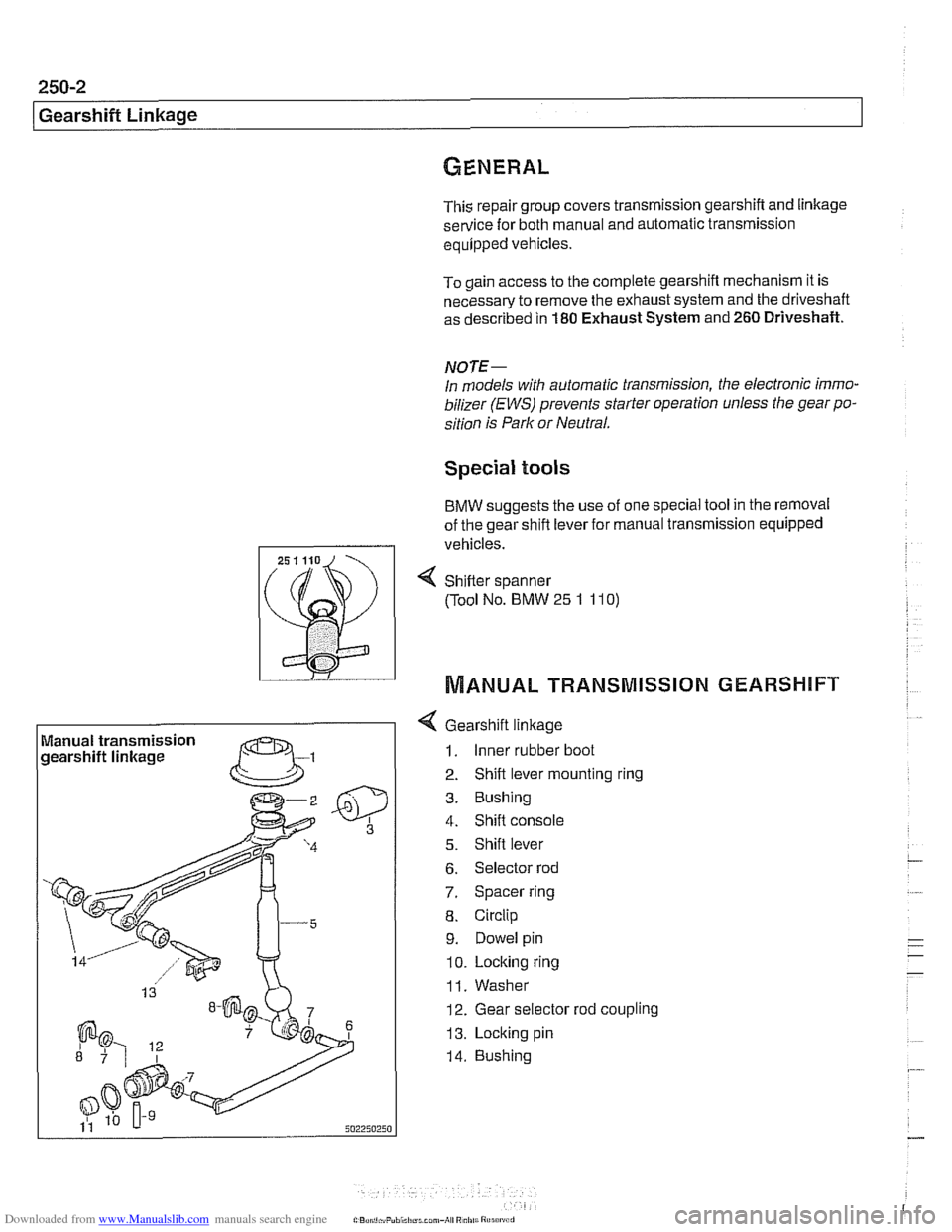
Manual transmission
gearshift linkage
--
4 Gearshift linkage
1. Inner rubber boot
2. Shift lever mounting ring
3. Bushing
4. Shift console
5. Shift lever
6. Selector rod
7. Spacer ring
8. Circlip
9. Dowel pin
10. Locking ring
11. Washer
12. Gear selector rod coupling
13. Locking pin
14. Bushing
4 Sh~fter spanner
(Tool No. BMW
25 1 11 0)
MANUAL TRANSMISSION GEARSHIFT
Page 601 of 1002

Downloaded from www.Manualslib.com manuals search engine
Gearshift ~inkaael
Gearshift lever, removing
(manual transmission)
Use the accompanying illustration as a guide when removing
and installing the gearshift linkage.
- Remove shift knob by pulling knob straight off shift lever.
NOTE-
Pull up on the shift knob with about 90 lbs. of force. Do not
twist
knob or locating key can be damaged.
- Squeeze sides of shift boot to unclip from center console.
Pull boot up and off shift lever.
- Remove sound insulation at base of shift lever.
- Raise vehicle to gain access to underside of vehicle.
- --
WARNING-
Male sure the car is stable and well supported at all tfmes.
Use a professional automotwe hft orjaclc stands designed for
the purpose.
A floorjaclc 1s not adequate support.
- Remove complete exhaust system. See 180 Exhaust
System.
- Remove driveshaft. See 260 Driveshaft.
- Support transmission with transmission jack. Remove
crossmember from rear of transmission.
- Lower rear of transmission to access gearshift linkage.
CA UTIOI\C
Tilting the engine to lower the transmission can lead to
damage to various components due to lack of clearance.
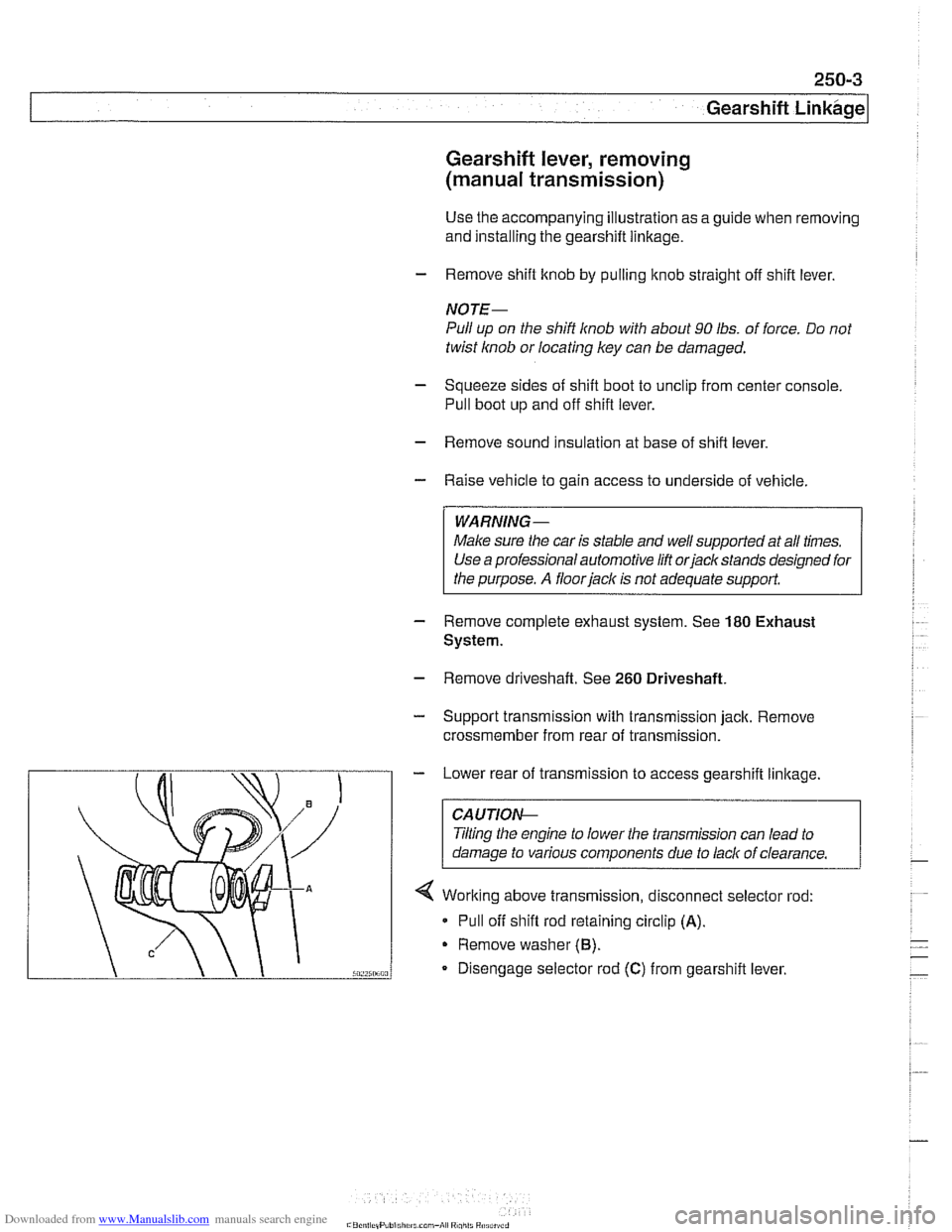
4 Working above transmission, disconnect selector rod:
* Pull off shift rod retaining circlip (A).
Remove washer (6).
Disengage selector rod (C) from gearshift lever.
Page 617 of 1002

Downloaded from www.Manualslib.com manuals search engine
Driveshaft
- Road test vehicle to check for noise or vibration
CAUTION-
Do not reuse self-locking nuts. These nuts are designed to
be used only once.
Avoid stressing the flex-disc when torquing the bolts.
Do this by counterholding the bolts and turning the nuts
on the flange side.
Tightening torques
Alunlinum driveshaft to flex-disc
- MI2 (use coated washers)
90 Nm (66 ft-lb)
Driveshaft
CV joint to final drive flange
Mi0 (Tom bolt)
70 Nm (51 ft-lb)
M8 (compression nut) 32 Nm (24 ft-lb)
Flex-disc to transmission flange or driveshaft
MI0 (8.8 grade) 48 Nm (35 ft-lb)
MI 0 (1 0.9 grade) 60 Nm (44 ft-lb)
- Mi2 (8.8 grade)
81 Nm (60 ft-lb)
- MI2 (10.9 grade) I00 Nm (74 ft-lb)
MI4 140 Nm (103 ft-lb)
Transmission
crossmember
to transmission (ME) 21 Nm (15 ft-lb)
. to chassis (M10) 42 Nm (30 ft-lb)
NOTE-
Boltgrade is marked on the bolt head. When replacing bolts,
only use bolts of the same strength and hardness as the orig-
inals installed.
Flex-disc, replacing
- Checlc flex-disc between front section of driveshafl and trans-
mission output flange for craclts, tears, missing pieces, or
distortion. Check for worn bolt hole bores in flange.
- If flex-disc needs replacement, remove driveshafl as de-
scribed earlier.
- Unbolt flex-disc from driveshaft.
NOTE-
Removal andinstallation of the bolts may be made easier by
placing a large hose clamp around the flex-disc, and tighten-
ing the clamp slightly to compress the rubber.
Page 618 of 1002

Downloaded from www.Manualslib.com manuals search engine
260-1 2
1 Driveshaft
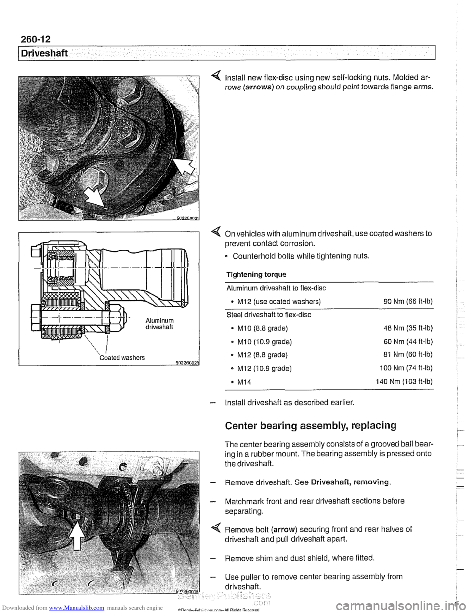
Install new flex-disc using new self-locking nuts. Molded ar-
rows (arrows) on coupling should point towards flange arms.
4 On vehicles with aluminum driveshaft, use coated washers to
prevent contact corrosion.
- Counterhold bolts while tightening nuts.
Tightening torque
Aluminum driveshaft to flex-disc
M12 (use coated washers) 90
Nm (66 ft-lb)
Steel driveshaft to flex-disc
MI0 (8.8 grade) 48
Nm (35 ft-lb)
- MI0 (10.9 grade) 60 Nm (44 ft-lb)
Coated washers - MI2 (8.8 grade) 5027500 . Mi2 (10.9 grade)
M14 81
Nm (60 ft-lb) 100 Nm (74 ft-lb)
140 Nm (103 ft-lb)
- Install driveshaft as described earlier
Center bearing assembly, replacing
The center bearing assembly consists of a grooved ball bear-
ing in a rubber mount. The bearing assembly is pressed
the driveshaft.
- Remove driveshaft. See Driveshaft, removing
- Matchmark front and rear driveshaft sections before
separating.
Remove bolt (arrow) securing front and rear halves of
driveshaft and pull driveshaft apart.
- Remove shim and dust shield, where fitted
- Use puller to remove center bearing assembly from
driveshaft. onto
Page 620 of 1002

Downloaded from www.Manualslib.com manuals search engine
260-14
Driveshaft
Constant velocity (CV) joint, replacing
The CV joint at the rear of the driveshaft is available from
BMW as a separate part.
- Remove complete driveshaft as described earlier in this
section.
< Clean grease off CV joint. Remove retaining circlip (arrow)
from CV joint end of driveshaft.
- Drive out bolts from CV joint.
4 Remove CV joint from driveshaft:
Pry back protective boot
(A).
- Using BMW special tool 26 1 110 on inner race (B), press
or pull joint off shaft.
- Check protective boot for damage. Replace if necessary.
- lnstall new CV joint:
. Working from both sides of joint, inject approximately 80
grams of
OptimolB grease (or equivalent) into joint.
Install new sealing gasket on joint face that mates with pro-
tective boot. Seal fits in groove on outer race of joint.
Clean grease off driveshaft and mating splines on joint.
Apply
LoctiteO 648 to driveshaft splines.
Press new CV joint onto shaft as far as it will go.
CAUTIOI\C
Only press on inner CVjoint race.
- Install new retaining circlip to end of driveshaft,
- Insert CV joint mounting bolts. Be sure to reuse washers.
- Install driveshaft as described earlier in this section.
Page 645 of 1002
Downloaded from www.Manualslib.com manuals search engine
31 0-9
Front Suspension
Front strut assembly
components
(6-cylinder models)
1. Cap
2. Upper strut self-locking nut
3. Washer
4. Strut bearing reinforcement
5. Strut mount self-locking nut
6. Upper strut mount
7. Dust protector collar
8. Spacer
9. Upper spring seat
10. Spacer
11. Upper spring pad
12. Coil spring
13. Rubber stop
14. Dust boot
15. Lower strut pad
16. Strut with lower spring seat
Front strut assembly, disassembling
and assembling
Replacing the strut, upper strut mount or spring requires that
the strut assembly first be removed from the car
and disas-
sembled. For a guide to parts used during component re-
placement, see the accompanying diagram.
NOTE-
Illustration shows components ior 6-cylinder models (525i,
528i, 530;). V-8 models (540i) are similar but not identical.
Page 675 of 1002

Downloaded from www.Manualslib.com manuals search engine
Steering and Wheel Alignment
Power assist is provided by a belt-driven pump at the lower
left front of the engine. The power steering fluid reservoir is lo-
cated at the left side of the engine compartment.
Power steering pump, removing and
installing
When working with power steering components, absolute
cleanliness is needed to ensure proper operation of the hy-
- Empty power steering fluid reservoir using clean syringe. Do
not reuse fluid.
- Raise front of car. Remove splash shield from under engine.
WARNING-
Make sure the car is firmly supported on jack stands de-
signed for the purpose. Place jack stands beneath structural
chassis points. Do not place jack stands under suspension
Darts.
Remove drive belt from power steering pump. See
020 Main-
tenance.
Remove alternator cooling duct
Remove fluid hoses from pump. Plug openings in pump and
hose ends.
Remove pump front mounting bolts
(A).
Remove fluid line support bracket (B)
Remove pump rear mounting bolt (arrow)
- Installation is reverse of removal, noting the following:
Make sure all thread bores, bolts, nuts, fluid couplings and
mating
surfaces are clean, and inside surface of multi-
ribbed-belt is free of grease and dirt.
Use new sealing washers when reattaching power steer-
ing pressure lines.
Make sure hoses have adequate clearance from chassis.
Install front pump fasteners.