2000 BMW 528i Air temperature sensor
[x] Cancel search: Air temperature sensorPage 469 of 1002

Downloaded from www.Manualslib.com manuals search engine
Fuel Injection I
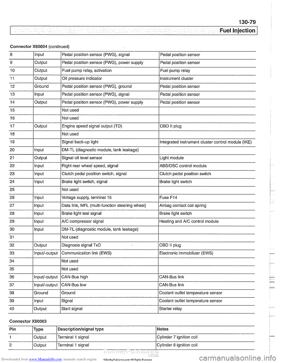
Connector X60004 (continued)
8 10
11
12
13
14
15
16
9
Output 0
Input
17
18
19
20
21
22
23
24
25
26
27
28
29
30
31
32
33
34
35
36
39
llnput lsignal l~oolant outlet temperature sensor
Output
Output
Ground
Input
Output
I I - I
40 /output Istart signal Istarter relay
Pedal position sensor (PWG), signal
Output Input
Output
input
Input
Input
Input
Input
Input
input
Input
Output
Input/-output
Input/-output
37
Connector X60003
Pedal position sensor
Fuel pump relay, activation
Oil pressure indicator Pedal position sensor (PWG), ground
Pedal position sensor (PWG), signal
Pedal position sensor (PWG), power supply
Not used
Not used Fuel
pump relay
Instrument cluster
Pedal position sensor
Pedal position sensor
Pedal position sensor
Engine speed signal output (TD)
Not used
Signal
back-up light
DM-TL (diagnostic module,
tank leakage)
Signal oil level sensor
Right rear wheel speed, signal
Clutch pedal position switch, signal
Brake light switch, signal
Not used
Voltage supply, terminal
15
Data link, MFL (multi-function steering wheel)
Brake light test signal
AJC compressor signal
DM-TL (diagnostic module, tank
leakage)
Not used
Diagnosis signal
TxD
Communication link (EWS)
Not used
Not used
CAN-BUS hiqh
38 1 Ground l~round I Coolant outlet temperature sensor
OED II plug
Integrated instrument cluster control module (IKE)
Light module
ABSIDSC control module
Clutch pedal position switch
Brake light switch
Fuse
F14
Airbag contact coil spring
Brake light switch
Heating and
A/C control module
OBD
II plug
Electronic immobilizer (EWS)
CAN-Bus link
CAN-Bus link
Input/-output CAN-Bus low
Page 524 of 1002

Downloaded from www.Manualslib.com manuals search engine
180-2
Exhaust System
The exhaust system is designed to be maintenance free, al-
though regular inspection is warranted due to the harsh oper-
ating conditions. Under normal conditions, the catalytic
converter does not require replacement unless it is damaged.
New fasteners, clamps, rubber mounts and gaskets should
be used when replacing exhaust components.
A liberal appli-
cation of penetrating oil to the exhaust system nuts and bolts
in advance may make removal easier.
WARNING -
The exhaust system and catalytic converter operate at
very high temperatures. Allow components to cool before
servicing. Wear protective clothing to prevent burns.
Do not use flammable chemicals near a hot
cataiyiic
converter.
Corroded exhaust system components crumble easily
and often have exposed sharp edges. To avoid injury,
wear eye protection and heavy gloves when working
Exhaust system, removing and installing
The removal and installation procedures given here are gen-
eral procedures for all models. The removal of the exhaust
system as a complete unit is recommended. Once the com-
plete system is removed from the car, individual pipes and
mufflers can be more easily replaced.
WARNING-
Exhaust gases are colorless, odorless, and very toxic. Run
the engine only in a well-ventilated area. Immediately repair
any
leaks in the exhaust system or structural damage to the
car body that
might allow exhaust gases to enter the passen-
ger compartment.
CAUTION-
Use care not to drag or bang oxygen sensors. Oxygen sen-
sors can be easily ruined.
Page 727 of 1002

Downloaded from www.Manualslib.com manuals search engine
Rear Suspension
- Remainder of installation is reverse of removal, noting the fol-
lowing.
Tighten suspension arm and shock absorber fasteners to
final torque only afler vehicle has been lowered and sus-
pension has settled.
Tightening torques
ABS pulse sensor to wheel bearing carrier 8
Nrn (6 ft-lb)
Air line connection 2 Nrn (18 in-lb)
Brake rotor to hub 16
Nrn (12 ft-lb)
Driveshaft
CV joint to final drive flange
- MI0 (Torx bolts) 70
Nrn (51 ft-lb)
- MB (compression nut) 32 Nrn (24 ft-lb)
Rear
brake pad carrier (caliper) to wheel 65
Nrn (48 ft-lb)
bearing carrier
Road wheel to hub
120ilO Nrn
(89 i-7 ft-lb)
Rear subframe mounting bushings,
removing and installing
- Remove rear subframe mounting bolts as described earlier.
Lower
subframe approximately 40 - 45 mm (1 -2 in).
4 Install BMW special tools 33 4 140,33 4 151,33 4 154,33 4
155,33 4 156 as shown.
Use hot air gun with a maximum output temperature of
600°C (1100" F) to heat bushing area of subframe for no
more than
2 minutes. Remove rubber mount from sub-
frame.
CAUTION-
Aluminum suspension parts may be severely damaged
witli intense heat
* Heating for 2 minutes with the recommended heat
source is intended to
keep the temperature of the alu-
minum
parts below the safety threshold of 80°C
(1 76°F). .
Page 973 of 1002

Downloaded from www.Manualslib.com manuals search engine
On-Board Diagnostics
l~utomatic transmission diagnostic trouble codes (continued)
P-code
1 Pi844
I I
14 /Pressure Control Solenoid 'D' Circuit Low
I I PI841 11 /Pressure Control Solenoid 'A' Circuit Low
BMW-FC
Pi842
I
P2722 15 I Pressure Control Solenoid 'E' I
DTC
Definition
Pi 845
Pi 882
Pi 883
PI 889
PI891
PI 892
PI 893
Pi 843 3 8
2 Pressure Control Solenoid '0' Circuit Low
5
57
58
96
96
96
83
P2729
P2730
P2759
P2761
P2763
P2764
Pressure Control Solenoid 'E' Circuit Low
2-3 Shift Circuit High
3-4 Shift Circuit High
System Voltage
- Electrical
System Voltage High Input
System Voltage Low Input
SUDP~V Voltaqe Pressure Control SoienoidIShift Solenoid Circuit High
~~ ~~ ~ Engine diagnostic trouble codes: M52 engine
5
5
4
4
4
4
I I
Pressure Control Solenoid 'E' Control Circuit Low
Pressure Control Solenoid
'E' Control Circuit High
Torque Converter Clutch Pressure Control
Solenoid Control Circuit Electrical
Torque Converter Clutch Pressure Control Solenoid Control
Circuitlopen
Torque Converter Clutch Pressure Control Solenoid Control Circuit High
Torque Converter Clutch Pressure Control Solenoid Control Circuit Low
DTC Definition
Mass or Volume Air
Flow Circuit RangeIPerformance
lntalte Air Temperature Sensor 1 Circuit Rangelperformance
Engine Coolant Temperature Circuit RangeIPerformance
ThrottieIPedai Position SensorISwitch 'A' Circuit
ThrottleIPedai Position SensorISwitch 'A' Circuit
P-code
PO1
01
PO1 11
PO116
PO120
PO120
PO1 20 BMW-FC
8 14
10
112
113
POI 20 1173 /~hrottie/~edal Position SensorISwitch 'A' Circuit
118
ThrottieIPedai Position SensorISwitch 'A' Circuit
Page 975 of 1002

Downloaded from www.Manualslib.com manuals search engine
OBD-15
On-Board ~iagnosticsl
Engine diagnostic trouble codes: M52 engine (continued)
P-code
PO340
PO412
PO420
PO430
PO440
PO441
PO442
PO443
PO500
PO505
PO600
PO601
PO601
I PO601
~1132
~1133
BMW-FC
65
62
233
234
250 144
-
145
68
214
i I
DTC Definition
Camshalt Position Sensor 'A' Circuit (Bank 1 or Single Sensor)
Secondary Air Injection System Switching Valve A Circuit
Catalyst System Efficiency Below Threshold
(Bank 1)
Catalyst System Efficiency Below Threshold (Bank 2)
Evaporative Emission System
Eva~orative Emission Svstem Incorrect Purge Flow .
Evaporative Emission System Leak Detected (small leak)
Evaporative Emission System Purge Control Valve Circuit
Vehicle Speed Sensor 'A'
204
21 7
100
170
171
188
189
PI161
PI180
PI181
PI184
PI185
PI178
02 Sensor Heater Control Circuit (Bank 2 Sensor 2) I
idle Air Control System
Serial Communication
Link
Internal Control Module Memory Check Sum Error
Internal Control Module Memory
Check Sum Error
Internal Control Module Memory
Check Sum Error
02 Sensor Heater Control Circuit (Bank 1 Sensor
1)
02 Sensor Heater Control Circuit (Bank 2 Sensor 1)
Mass or Volume Air Flow Circuit RangeIPerlormance Problem PI140
I
I I
P1188 1227 I Fuel Control (Bank 1 Sensor 1)
PI145 150 /Solenoid Valve Running Losses Control Circuit Electrical
149
122
223
224
220 221
231
I I
P1189 1228 I Fuel Control (Banlc 2 Sensor 1)
Fuel Trim Adaptation Additive High (Bank 2) (M52: Engine Oil Temperature Sensor Circuit)
02 Sensor Signal Circuit Slow Switching from Rich to Lean
(Bank 1 Sensor 2)
02 Sensor Signal Circuit Slow Switching from Rich to Lean
(Bank 2 Sensor 2)
H02S Sensor Voltage Excursion Electrical (Banlc 1 Sensor 1)
HO2S Sensor Voltage Excursion Electrical (Banlc 2 Sensor 1)
02 Sensor Sianai Circuit Slow Switchina from Rich to Lean (Bank 1 Sensor 1)
02 Sensor Signal Circuit Slow Switching from Rich to Lean (Bank 2 Sensor 1) PI179
I I
PI190 1235 I Pre Catalyst Fuel Trim System (Banlc 1)
PI186 1190 102 Sensor Heater Control Circuit (Banlc 1 Sensor 2)
232
I I
PI191 1236 I Pre
Catalyst Fuel Trim System (Banlc 2)
PI192
. . -- - i Pi193 1226 I Post Catalvst Fuel Trim Svstem (Bank 2)
225
PI397
I I
Post Catalyst Fuel Trim System (Bank 1)
PI421 1246 /Secondarv Air System (Bank 2)
18
Secondary Air System (Bank
1) PI423
Camshaft Position Sensor '0' Circuit (Bank 1)
I 245
Page 977 of 1002

Downloaded from www.Manualslib.com manuals search engine
On-Board ~iaanosticsl
Engine diagnostic trouble codes: M54 engine
P-code
BMW-FC Explanation
PO01 I / 103 I 'A' Camshaft Position Timing Over-Advanced or System Performance (Banlc 1) I I
PO012 1105 I 'A' Camshaft Position Timing Over-Retarded (Bank 1) I I
PO01 4 1104 I 'B' Camshaft Position Timing Over-Advanced or System Performance (Bank 1)
PO01 5
PO030
PO031
PO032
I 1
PO038 179 / HO2S Heater Control Circuit High (Bank 1 Sensor 2)
I I -.
I I
PO050 1 55 I H02S Heater Control Circuit (Bank 2 Sensor 1)
106
25
25
25
PO036
I I
PO051 1 55 I H02S Heater Control Circuit Low (Bank 2 Sensor 1)
'B' Camshaft Position Timing Over-Retarded (Bank 1)
H02S Heater Control Circuit (Bank 1 Sensor 1)
H02S Heater Control Circuit Low (Bank 1 Sensor 1)
H02S Heater Control Circuit Hiqh (Bank 1 Sensor 1)
PO037 1 79 I HO2S Heater Control Circuit Low (Bank 1 Sensor 2)
79
HOPS Heater
Control Circuit (Banlc 1 Sensor 2)
PO052
PO056
PO057
PO058
I I
PO1 03 / 8 I Mass or Volume Air Flow Circuit High. Input
I I -.
I I
PO1 07 1 197 I Manifold Absolute PressureIBarometric Pressure Circuit Low Input
55
61
61
61
PO101
I I
POI08 1197 / Manifold Absolute PressureIBarometric Pressure Circuit High Input
H02S Heater Control Circuit High (Bank 2 Sensor 1)
H02S Heater Control Circuit (Bank 2 Sensor 2)
HO2S Heater Control Circuit Low (Bank 2 Sensor 2)
HO2S Heater Control Circuit Hiqh (Banlc 2 Sensor 2)
PO102 18 I Mass or Volume Air Flow Circuit Low Input
149
I I -
PO122 112 ThrottleIPedai Position SensorISwitch 'A' Circuit Low
PO123 1112 I ThrottleIPedal Position SensorISwitch 'A' Circuit High
Mass
or Volume Air Flow Circuit
RangeIPerformance
PO112
PO113
PO1 17
PO118
PO121
14
14
10
10
118
PO128
PO1 31
PO132
PO133
PO133
PO1 34 Intake
Air Temperature Sensor 1 Circuit Low
Intake Air Temperature Sensor 1 Circuit High
Engine Coolant Temperature Circuit Low
Engine Coolant Temperature Circuit High
ThrottleIPedal Position SensorISwitch 'A' Circuit RanqeIPerformance
I I
168
150
150
229
231
150
PO135
Coolant Thermostat (Coolant Temperature Below Thermostat Regulating Temperature)
02 Sensor Circuit Low Voltage (Bank 1 Sensor 1)
02 Sensor Circuit High Voltage (Bank 1 Sensor 1)
02 Sensor Circuit Slow Response (Bank
1 Sensor 1)
02 Sensor Circuit Slow Response
(Banlc 1 Sensor 1)
02 Sensor Circuit No Activitv Detected
(Banlc 1 Sensor 1)
188 02 Sensor Heater Circuit (Bank 1 Sensor 1)
Page 980 of 1002

Downloaded from www.Manualslib.com manuals search engine
I On-Board Diagnostics
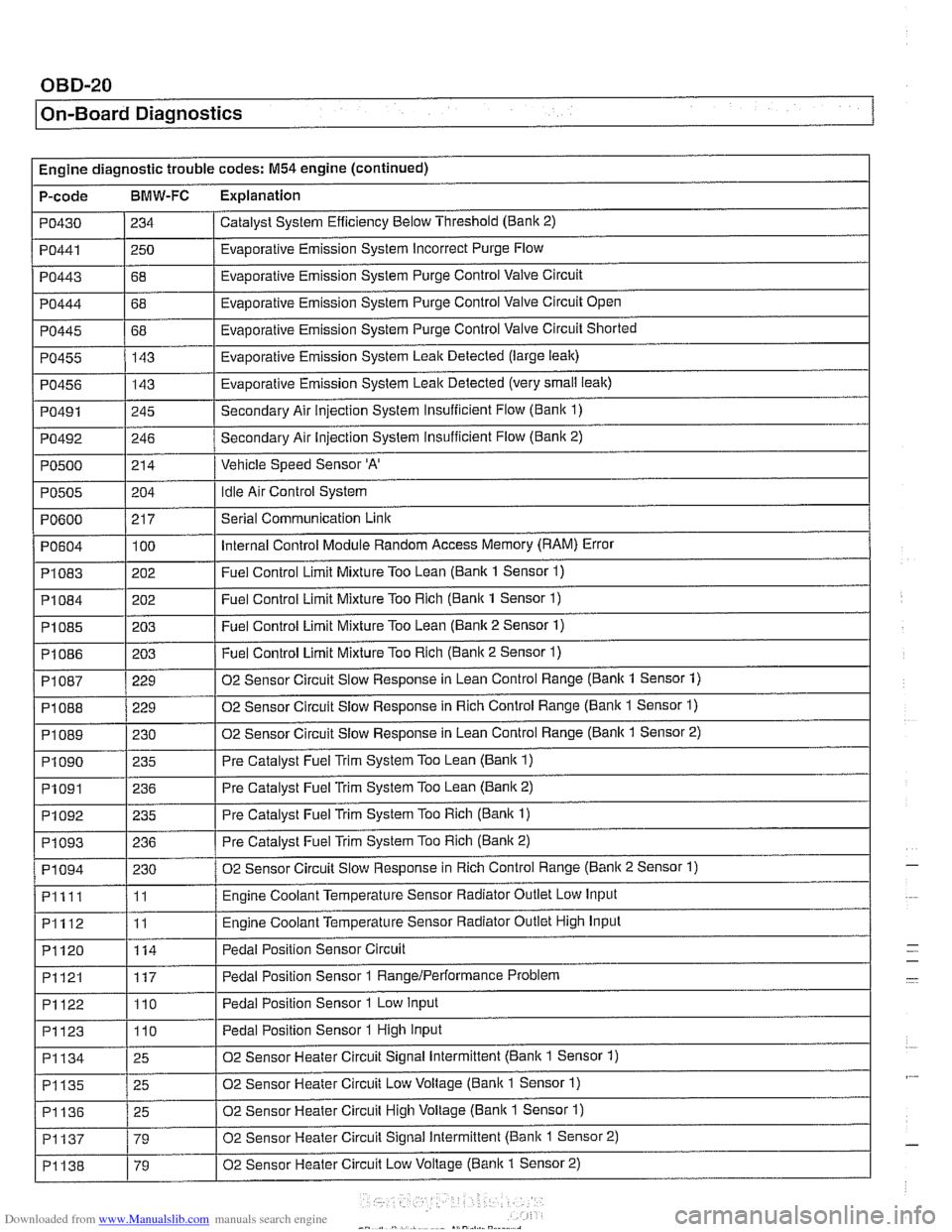
Engine diagnostic trouble codes: M54 engine (continued)
P-code
BMW-FC Explanation
Catalyst System Efficiency Below Threshold (Bank 2)
PO430
PO443
PO444
PO445
PO455
PO456
PO491
PO492
PO500
PO441 1250 / Evaporative Emission System Incorrect Purge Flow
234
I I
68
68
68 143
143
245
246
214
PO604
PI083
PI084
PI085
PI086
Evaporative Emission System Purge Control Valve Circuit
Evaporative Emission System Purge Control Valve Circuit Open
Evaporative Emission System Purge Control Valve Circuit Shorted
Evaporative Emission System Leak Detected (large leak)
Evaporative Emission System Leak Detected (very
small leak)
Secondary Air injection System Insufficient Flow (Bani( 1)
Secondary Air Injection System insufficient Flow
(Banic 2)
Vehicle Speed Sensor
'A'
Idle Air Control System PO505
.
PI 087
PI 088
PI089
PI090
PO600 / 217 I Serial Communication Link
204
100
202
202
203
203
PI091
PI092
PI093
PI094
Pllll
PI112
PI120
Internal Control Module Random Access Memory (RAM) Error
Fuel Control Limit Mixture Too Lean (Bank 1 Sensor
1)
Fuel Control Limit Mixture Too Rich (Bank 1 Sensor 1)
Fuel Control Limit Mixture Too Lean (Bank 2 Sensor 1)
Fuel Control Limit Mixture Too Rich (Banic 2 Sensor 1) ~ ~
229
229
230 235
PI121
PI122
PI123
02 Sensor Circuit Slow Response in Lean Control Range (Bank 1 Sensor 1)
02 Sensor Circuit Slow Response in Rich Control Range (Bank 1 Sensor
1)
02 Sensor Circuit Slow Response in Lean Control Range (Banlc 1 Sensor 2)
Pre Catalyst Fuel Trim System Too Lean
(Bank 1)
236
235
236
230
11
11
114
PI134
PI135
PI136
PI137
PI138
Pre Catalyst Fuel Trim System Too Lean (Banic 2)
Pre Catalyst Fuel Trim System Too Rich
(Bank 1)
Pre Catalyst Fuel Trim System Too Rich (Bank 2)
02 Sensor Circuit Slow Response in Rich Control Range (Banic 2 Sensor 1)
Engine Coolant Temperature Sensor Radiator Outlet Low Input
Engine Coolant Temperature Sensor Radiator Outlet High Input
Pedal Position Sensor Circuit
117
110
110
25
25
25
79
79 Pedal Position Sensor 1
RangeIPerformance Problem
Pedal Position Sensor 1 Low Input
Pedal Position Sensor 1 High Input
02 Sensor Heater Circuit Signal Intermittent (Bank 1 Sensor 1)
02 Sensor Heater Circuit Low Voltage (Bank 1 Sensor
1)
02 Sensor Heater Circuit High Voltage (Bank 1 Sensor 1)
02 Sensor Heater Circuit Signal Intermittent (Bank 1 Sensor 2)
02 Sensor Heater Circuit Low Voltage
(Banic 1 Sensor 2)
-
-
Page 984 of 1002

Downloaded from www.Manualslib.com manuals search engine
/ On-Board Diaanostics I
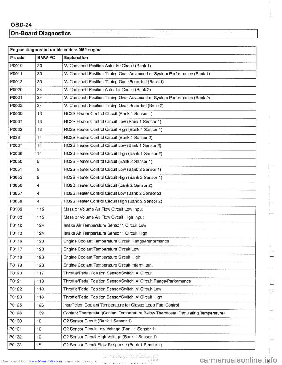
Engine diagnostic trouble codes: M62 engine
P-code
PO01 1
PO012
PO020
PO021
PO022
PO030
PO031
PO032
I I
PO038 / 14 I H02S Heater Control Circuit High (Bank 1 Sensor 2)
PO010 / 33 / 'A' Camshaft Position Actuator Circuit (Bank 1)
BMW-FC
I I -.
Explanation
33
33
34
34
34 13
13
13
PO36
'A' Camshaft Position Timing Over-Advanced or System Performance (Bank 1)
'A' Camshaft Position Timing Over-Retarded (Bank 1)
'A' Camshaft Position Actuator Circuit (Bank 2)
'A' Camshaft Position Timing Over-Advanced or System Performance (Banlc 2)
'A' Camshaft Position Timing Over-Retarded (Banlc 2)
H02S Heater Control Circuit (Bank 1 Sensor 1)
H02S Heater Control Circuit Low (Bank 1 Sensor 1)
HOPS Heater Control Circuit Hiqh (Banlc 1 Sensor 1)
PO050
PO051
PO052
PO056
PO057
PO058
PO037 / 14 / H02S Heater Control Circuit Low (Bank 1 Sensor 2)
14
I I -.
Ir-1 ThrottleIPedal Position SensorISwitch 'A' Circuit
Low-
HO2S Heater Control Circuit (Bank 1 Sensor 2)
5
5
5
4
4
4
PO102
PO1 13
PO116
PO117
PO118
PO119
PO120
PO121
H02S Heater Control Circuit (Banlc 2 Sensor 1)
H02S Heater Control Circuit Low (Bank 2 Sensor 1)
H02S Heater Control Circuit High (Bank 2 Sensor 1)
H02S Heater Control Circuit (Bank 2 Sensor 2)
HO2S Heater Control Circuit Low (Bank 2 Sensor 2)
HO2S Heater Control Circuit Hiqh (Bank 2 Sensor 2)
PO103 1115 I Mass or Volume Air Flow Circuit High Input
115
124
123
123
123
123
117
118
PO1 23
PO125
PO128
PO1 30
PO131
POI 32
PO133
Mass or Volume Air Flow Circuit Low Input
lntalte Air Temperature Sensor 1 Circuit High
Engine Coolant Temperature Circuit
RangeIPerlormance
Engine Coolant Temperature Circuit Low
Engine Coolant Temperature Circuit High
Engine Coolant Temperature Circuit Intermittent
ThrottleIPedal Position SensorISwitch 'A' Circuit
ThrottieIPedal Position SensorISwitch 'A' Circuit RanqeIPerformance
118
123 139
10
10
10
15
ThrottleIPedai Position SensorlSwitch 'A' Circuit High
insufficient Coolant Temperature for Closed Loop Fuel Control
Coolant Thermostat (Coolant Temperature Below Thermostat Regulating Temperature)
02 Sensor Circuit (Bank
1 Sensor 1)
02 Sensor Circuit Low Voltage (Bank 1 Sensor 1)
02 Sensor Circuit High Voltage (Bank
1 Sensor 1)
02 Sensor Circuit Slow Response (Bank 1 Sensor
1)